
QSFP28-DD is designed to meet the increasing demand for higher bandwidth and port density in modern data centers. Building on QSFP28 standards, it introduces a dual-row contact design that doubles the number of electrical lanes, enabling greater data throughput without increasing the physical footprint.
This enhancement makes QSFP28-DD a key solution for high-density networking, improving faceplate efficiency while supporting advanced physical layer requirements. Understanding its architecture is essential for deploying scalable, high-performance systems in next-generation data center environments.
? Evolution of High-Density Ports: From QSFP28 to QSFP28-DD
The transition from QSFP28 to QSFP28-DD reflects the industry’s need for higher bandwidth without increasing physical port size. By extending the electrical interface from 4 lanes to 8 lanes, QSFP28-DD enables significantly higher data rates while maintaining backward compatibility. This evolution is driven by standardized design principles and innovations in connector architecture.
Understanding the Multi-Source Agreement (MSA) Foundations
QSFP28-DD is defined by the QSFP-DD Multi-Source Agreement (MSA), which ensures interoperability across vendors and consistency in mechanical, electrical, and management interfaces. Key aspects include:
- Standardized electrical interface supporting 8 lanes at 25Gb/s (NRZ) or higher per lane.
- Defined mechanical envelope to maintain compatibility with existing QSFP ports.
- Compliance with CMIS (Common Management Interface Specification) for module management.
The MSA framework allows ecosystem-wide adoption, reducing vendor lock-in and accelerating deployment in large-scale networks.
The Dual-Row Contact Innovation in QSFP28-DD Modules
The defining innovation of QSFP28-DD is its dual-row contact design, which effectively doubles the number of electrical connections within the same connector footprint. Unlike QSFP28’s single row of contacts, QSFP28-DD introduces an additional row positioned behind the original interface.
- Front Row: Maintains compatibility with QSFP28 modules.
- Rear Row: Adds four extra high-speed lanes for expanded bandwidth.
- Total: 8 electrical lanes supporting up to 200G (NRZ) or 400G (PAM4).
This layered contact approach enables higher performance without requiring larger ports, preserving existing infrastructure investments.
Impact on Port Density and Faceplate Efficiency
QSFP28-DD significantly improves port density by delivering higher bandwidth per port while keeping the same physical dimensions as QSFP28. This has a direct impact on switch and router design:
- Doubled bandwidth per port reduces the number of required physical ports.
- Higher switch radix enables more connections within the same chassis.
- Improved faceplate utilization allows more ports per rack unit.
- Reduced cabling complexity and better airflow management.
As a result, QSFP28-DD supports more scalable and efficient data center architectures, particularly in hyperscale environments where space and power efficiency are critical.
? Anatomizing the QSFP28-DD Mechanical Form Factor and Geometry
The QSFP28-DD mechanical design is engineered to deliver higher performance while preserving the familiar QSFP footprint. It achieves this by integrating additional electrical interfaces within tightly controlled physical dimensions. This balance between compactness and functionality is critical for supporting high-density deployments in modern network equipment.
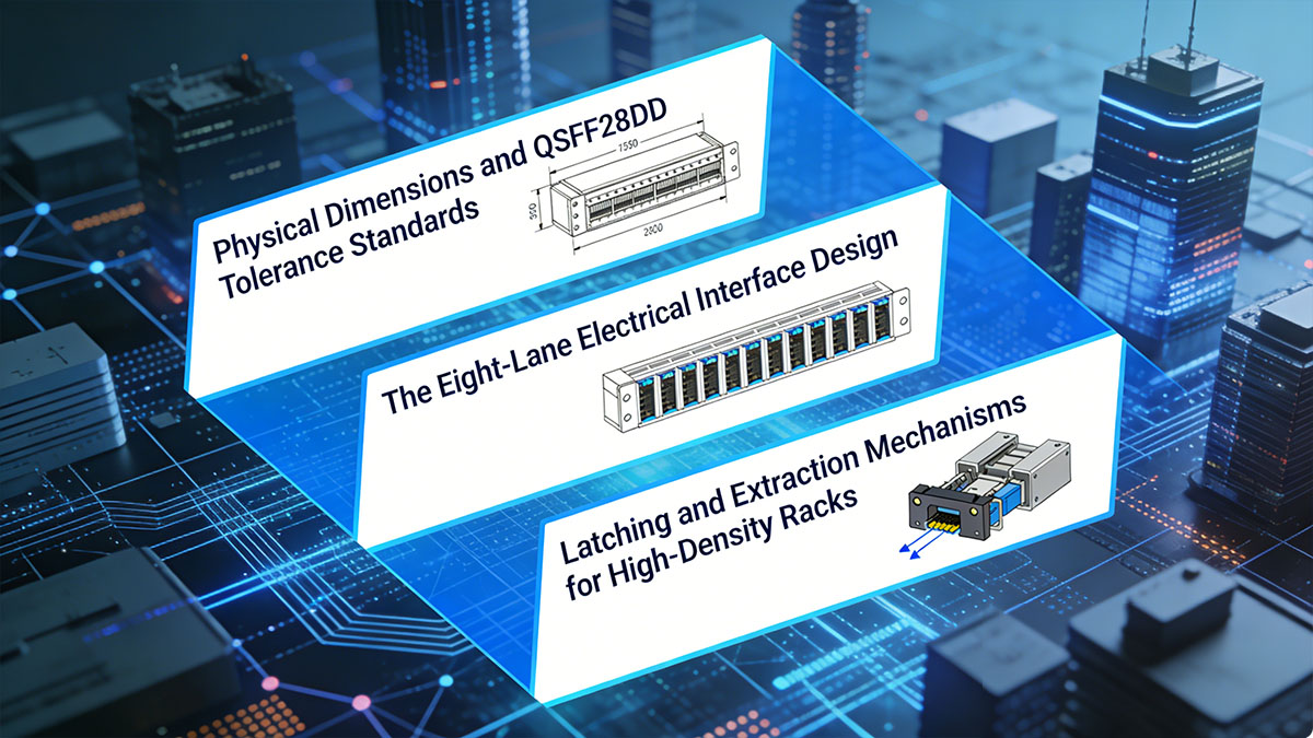
Physical Dimensions and Tolerance Standards
QSFP28-DD modules retain the same width and front-panel profile as QSFP28, ensuring compatibility with existing cage designs, while extending slightly in depth to accommodate the additional contact row. The MSA defines strict mechanical tolerances to ensure reliable insertion and consistent alignment across vendors.
Key considerations include:
- Standardized module width (18.35mm) and height (8.5mm) for faceplate compatibility.
- Increased module depth to support dual-row contacts.
- Tight tolerance control for connector alignment and mating accuracy.
- Defined cage and connector specifications to ensure mechanical robustness.
These precise tolerances are critical for maintaining signal integrity and ensuring seamless interoperability in high-density environments.
The Eight-Lane Electrical Interface Design
The mechanical structure of QSFP28-DD directly supports its eight-lane electrical architecture by incorporating an additional row of contacts within the connector interface. This design enables twice the number of high-speed channels without increasing the port footprint.
- Front Contact Row: Supports legacy 4-lane QSFP28 operation.
- Rear Contact Row: Adds 4 additional high-speed lanes.
- Optimized pin layout to minimize crosstalk and insertion loss.
- Mechanical alignment features to ensure consistent electrical contact.
The integration of these eight lanes within a compact form factor is a key enabler of higher data rates, such as 200GBASE and 400GBASE Ethernet.
Latching and Extraction Mechanisms for High-Density Racks
In high-density rack environments, reliable insertion and removal mechanisms are essential for operational efficiency and hardware longevity. QSFP28-DD modules use enhanced latching systems designed for both robustness and ease of use.
- Push-pull tab or bail latch designs for tool-less operation.
- Secure locking mechanism to prevent accidental disconnection.
- Optimized extraction force to balance retention and serviceability.
- Compatibility with tightly spaced ports in high-density faceplates.
These mechanisms ensure that modules can be safely installed and removed even in crowded rack configurations, reducing maintenance complexity and minimizing the risk of damage.
? Decoding the Electrical Interface of QSFP28-DD Physical Layer
The electrical interface of the QSFP28-DD module is the cornerstone of its high-speed performance. This layer governs how eight high-speed differential lanes communicate between host and module, ensuring signal integrity across dense board layouts and stringent power budgets.
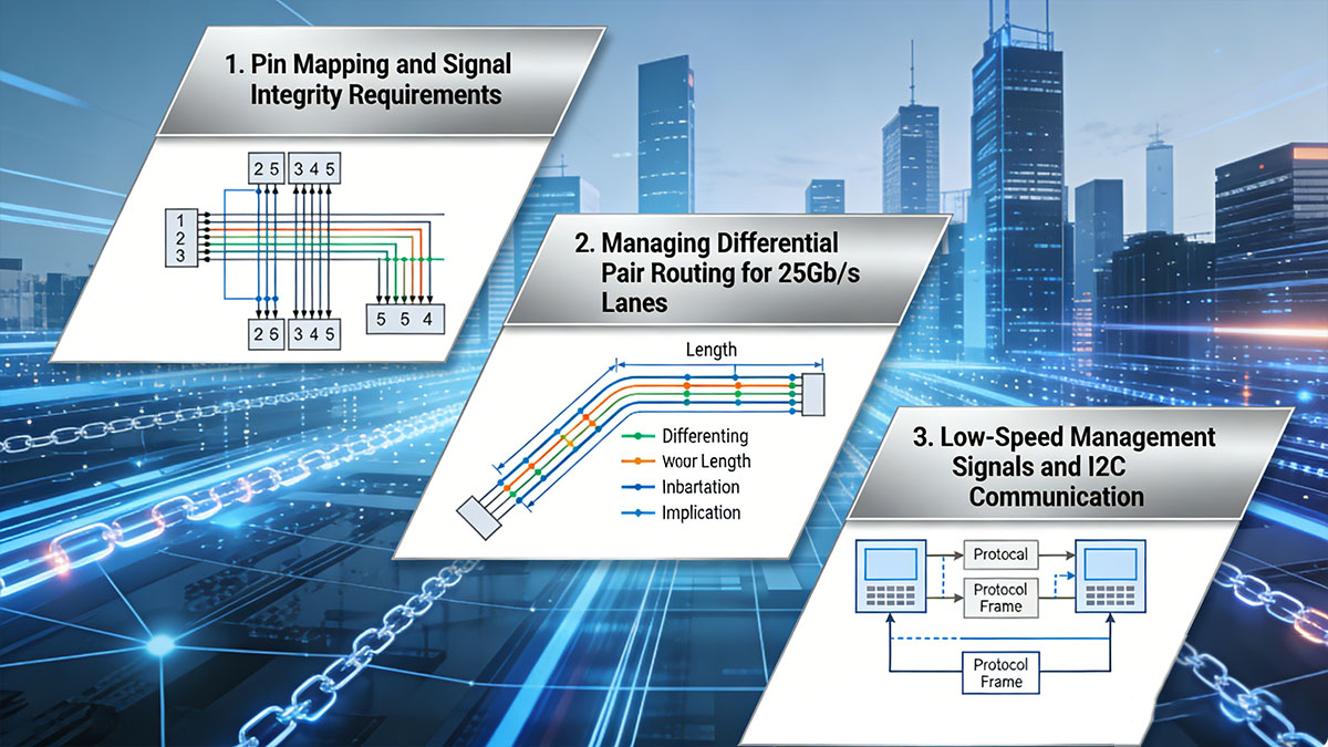
Pin Mapping and Signal Integrity Requirements
The QSFP28-DD connector introduces a 76-position contact layout arranged in two rows to support eight high-speed differential pairs. Each lane is designed to carry 25Gb/s or 50Gb/s PAM4 electrical signals, depending on the application. Ensuring signal integrity at these data rates demands controlled impedance (typically 85Ω ± 10%), careful impedance matching, and minimization of reflection and crosstalk. Designers employ strict compliance with the MSA pinout standard to ensure interoperability across multiple vendors.
Managing Differential Pair Routing for 25Gb/s Lanes
High-speed differential pairs in QSFP28-DD interconnects require consistent routing to maintain balanced delay, low skew, and minimal electromagnetic coupling. At 25Gb/s per lane, even small mismatches in trace length or impedance can degrade bit error rates and eye diagram performance. PCB designers follow guidelines such as maintaining equal-length trace pairs, using microstrip or stripline geometries, and spacing differential pairs at least three times the trace width to suppress crosstalk. This disciplined routing ensures that signals maintain integrity across complex backplane and connector transitions.
Low-Speed Management Signals and I2C Communication
Beyond the high-speed data lanes, QSFP28-DD modules incorporate low-speed control lines that facilitate management and monitoring via the I²C based CMIS interface. These signals handle tasks such as module identification, temperature and power monitoring, fault detection, and firmware updates. Operating typically at 3.3V logic levels, the low-speed interface ensures backward compatibility with legacy QSFP and QSFP28 devices while enabling enhanced digital diagnostics for next-generation modules. The reliable operation of these management channels is crucial for maintaining system visibility and operational stability in data center environments.
? Optical Connectivity Standards for QSFP28-DD Transceivers
The optical layer of QSFP28-DD modules defines how light-based data transmission occurs between transceivers, directly influencing link distance, power efficiency, and network scalability. These standards ensure interoperability across vendors and enable diverse deployment options ranging from short-reach intra-rack links to long-haul data center interconnects.
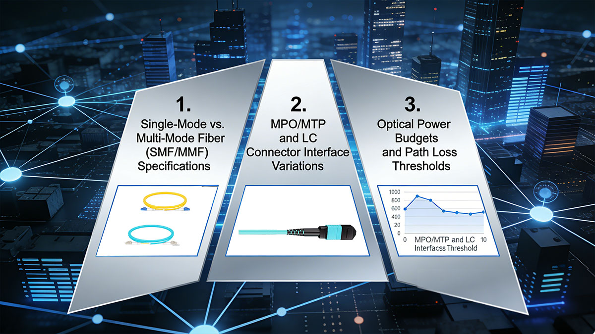
Single-Mode vs. Multi-Mode Fiber (SMF/MMF) Specifications
QSFP28-DD modules are compatible with both single-mode fiber (SMF) and multimode fiber (MMF), each suited for different transmission distances and cost considerations. SMF is typically used for long-distance, high-bandwidth links, while MMF is optimized for shorter, cost-sensitive deployments within data centers.
To better understand their differences, the following table provides a comparison:
| Parameter |
Single-mode Fiber (SMF) |
Multimode Fiber (MMF) |
| Core Diameter |
9µm |
50/62.5µm |
| Typical Distance |
Up to 10km |
Up to 100m |
| Wavelength |
1310nm or 1550nm |
850nm |
| Module Types Example |
QDD-400G-DR4-S, QDD-400G-FR4-S, QDD-400G-LR4-S |
400GBASE-SR8 |
| Cost |
Higher |
Lower |
| Use Case |
Long-haul Data Center or Campus Backbones |
Intra-rack or Short-range Links |
This comparison highlights that while SMF supports longer-reach and higher-capacity connections, MMF remains advantageous for cost-effective short-distance deployments within data halls.
MPO/MTP and LC Connector Interface Variations
QSFP28-DD transceivers support multiple connector types depending on the optical architecture, with MPO/MTP and LC being the most widely used. MPO/MTP connectors are typically used for parallel optics, while LC connectors are used for duplex transmission.
The following table highlights the key differences:
| Parameter |
MPO/MTP Connector |
LC Connector |
| Fiber Type |
Ribbon |
Duplex |
| Fiber Count |
8 or 16 Fibers |
2 Fibers |
| Use Case |
200G/400G Parallel Optics |
FR4/LR4 Optics |
| Density |
High |
Moderate |
| Deployment |
Spine-leaf, High-density Links |
General-purpose Links |
Optical Power Budgets and Path Loss Thresholds
Optical power budget is a critical parameter that determines the maximum allowable loss between transmitter and receiver while maintaining reliable communication. QSFP28-DD transceivers are designed with defined transmit (Tx) output power and receiver (Rx) sensitivity levels to meet specific standards such as SR, DR, FR, and LR.
Key factors influencing power budget include:
- Fiber attenuation (dependent on wavelength and distance).
- Connector and splice losses along the optical path.
- Insertion loss from connectors and patch panels.
- System margin to account for aging and environmental variations.
For example, short-reach multimode fiber modules (e.g., 400GBASE-SR8) typically have lower power budgets (~2 - 3dB), while long-reach single mode transceivers (e.g., 400GBASE-LR4/400GBASE-FR4) support higher budgets (6 - 10dB or more). Proper calculation of path loss ensures that the total link attenuation remains within the allowable budget, preventing signal degradation and link failure.
? Signal Integrity and EMI Mitigation in QSFP28-DD Architectures
As QSFP28-DD systems operate with higher lane counts and increased data rates, maintaining signal integrity becomes a key design challenge. High-speed transmission across dense interfaces introduces risks such as crosstalk, attenuation, and electromagnetic interference (EMI). To ensure reliable performance, both electrical and mechanical mitigation techniques must be carefully implemented.
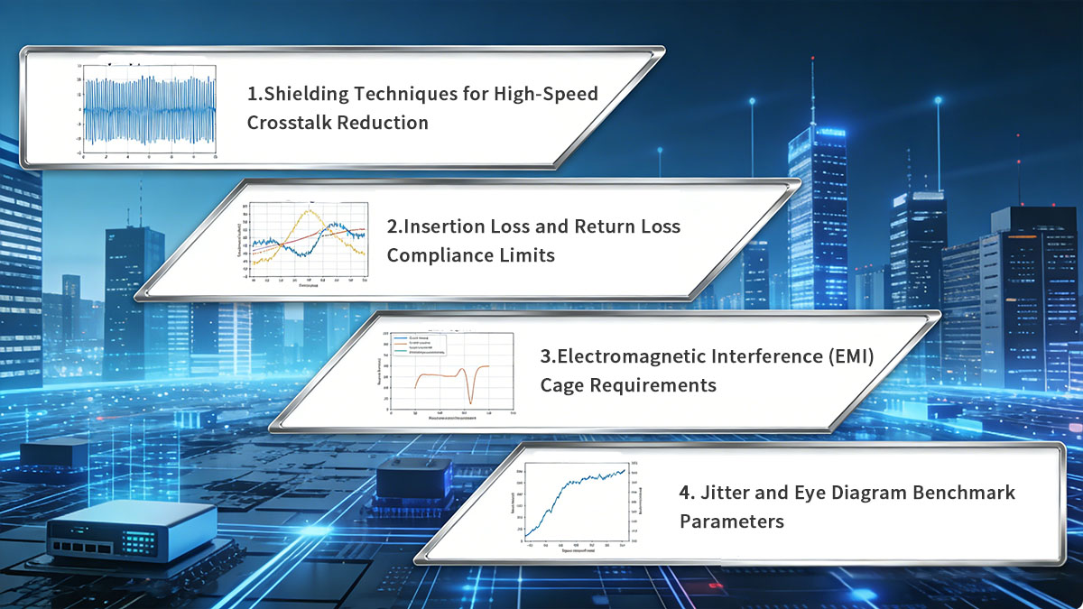
Shielding Techniques for High-Speed Crosstalk Reduction
In QSFP28-DD architectures, the proximity of multiple high-speed differential pairs increases the likelihood of crosstalk between adjacent channels. To address this, shielding is applied at both the module and PCB levels. Metal cages surrounding the module provide primary electromagnetic isolation, while internal connector shielding helps separate signal paths within the interface. These physical barriers reduce unwanted coupling and protect signal integrity in dense port configurations.
At the PCB level, designers further mitigate crosstalk through layout optimization. This includes maintaining proper spacing between differential pairs, implementing continuous ground planes, and using via stitching to contain electromagnetic fields. Additionally, differential signaling inherently suppresses common-mode noise, making it more resilient in high-interference environments. Together, these techniques ensure stable signal transmission even under high-density conditions.
Insertion Loss and Return Loss Compliance Limits
Insertion loss represents the attenuation of signal strength as it travels through the transmission channel, while return loss indicates reflections caused by impedance mismatches. In QSFP28-DD systems, both parameters must meet strict compliance limits defined by MSA and IEEE standards to ensure reliable high-speed communication. Excessive insertion loss can degrade signal amplitude, while poor return loss can introduce reflections that distort the signal.
To meet these requirements, careful channel design is essential. Engineers must control trace impedance, minimize discontinuities such as vias and connectors, and select low-loss PCB materials. In addition, signal conditioning techniques — such as transmitter pre-emphasis and receiver equalization — are widely used to compensate for channel impairments. These methods help maintain signal fidelity across the full transmission path.
Electromagnetic Interference (EMI) Cage Requirements
The QSFP28-DD cage plays a critical role in managing electromagnetic emissions and protecting the system from external interference. It is typically constructed as a fully enclosed metallic structure that surrounds the module, forming a continuous shielding barrier. This enclosure helps contain radiated emissions generated by high-speed signals and prevents them from affecting nearby components.
To ensure effective grounding, EMI cages incorporate features such as spring fingers or conductive gaskets that maintain consistent electrical contact between the module and the cage. Proper integration with the system chassis creates a unified grounding path, which is essential for meeting regulatory standards such as FCC and CISPR. In high-density switches, where multiple ports operate simultaneously, robust EMI containment is crucial for overall system stability.
Jitter and Eye Diagram Benchmark Parameters
Jitter refers to timing variations in the signal and is a key factor affecting data integrity in high-speed links. In QSFP28-DD systems, jitter is typically categorized into random jitter (RJ) and deterministic jitter (DJ), both of which can reduce timing margins and increase bit error rates. Managing jitter is essential to ensure that signals can be accurately sampled at the receiver.
Eye diagrams are commonly used to evaluate overall signal quality by visualizing voltage and timing characteristics. A well-defined eye opening indicates low noise, minimal distortion, and sufficient timing margin. Industry standards specify minimum eye height and width requirements that must be met for compliance. To achieve these benchmarks, advanced techniques such as digital signal processing (DSP) and forward error correction (FEC) are employed, helping to improve signal clarity and maintain reliable high-speed performance.
? Achieving Backward Compatibility with QSFP28-DD Ports
One of the key advantages of QSFP28-DD is its ability to maintain backward compatibility with existing QSFP28 modules. This ensures a smooth transition for network operators upgrading to higher bandwidth without replacing all legacy hardware. By combining mechanical compatibility with intelligent electrical and software design, QSFP28-DD enables flexible and cost-effective deployment.
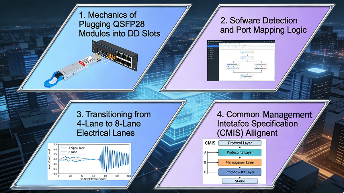
Mechanics of Plugging QSFP28 Modules into DD Slots
QSFP28-DD ports are physically designed to accept standard QSFP28 modules, thanks to their shared front-end connector dimensions. The front row of contacts in a QSFP28-DD port aligns directly with the single-row interface of QSFP28 modules, allowing seamless insertion without mechanical modification. This ensures that existing QSFP28 optical transceiver can be reused in newer QSFP28-DD-enabled systems.
However, since QSFP28 modules only utilize four electrical lanes, they do not engage the additional rear-row contacts present in QSFP28-DD ports. The port is engineered to accommodate this difference without compromising connection stability. Mechanical guides and alignment features ensure proper mating, while maintaining consistent insertion force and retention characteristics.
Software Detection and Port Mapping Logic
Backward compatibility is not only a mechanical feature but also relies heavily on software-level intelligence. When a QSFP28 module is inserted into a QSFP28-DD port, the system must automatically detect the module type and adjust its configuration accordingly. This is typically achieved through I2C-based communication and module identification protocols.
Once detected, the host system maps the available four lanes of the QSFP28 module to the corresponding subset of the eight available lanes in the QSFP28-DD port. Firmware and operating systems handle this mapping dynamically, ensuring correct data path configuration. This automatic adaptation allows mixed deployments without manual reconfiguration.
Transitioning from 4-Lane to 8-Lane Electrical Lanes
QSFP28 operates on a 4-lane architecture, while QSFP28-DD expands this to 8 lanes to support higher data rates. When transitioning between these modes, the system must manage differences in lane utilization and bandwidth allocation. In backward compatibility mode, only the first four lanes are activated, while the additional lanes remain idle.
In native QSFP28-DD operation, all eight lanes are used to enable higher throughput, such as 200G or 400G Ethernet. This flexible lane architecture allows network operators to gradually upgrade infrastructure. Systems can support both legacy and next-generation modules simultaneously, providing a scalable migration path.
Common Management Interface Specification (CMIS) Alignment
QSFP28-DD adopts the Common Management Interface Specification (CMIS) to standardize module management across different vendors and transceiver types. CMIS provides a unified framework for monitoring, configuration, and diagnostics, ensuring consistent behavior regardless of whether a QSFP28 or QSFP28-DD module is installed.
For backward compatibility, QSFP28-DD systems must support both CMIS and legacy management interfaces such as SFF-8636. This dual compatibility allows older QSFP28 modules to function correctly while enabling advanced features for QSFP28-DD modules. As a result, network operators benefit from enhanced management capabilities without sacrificing interoperability with existing hardware.
? Scaling Hyperscale Data Centers with QSFP28-DD Physical Layer
QSFP28-DD plays a pivotal role in enabling the scalability required by hyperscale data centers. By delivering higher bandwidth within the same physical footprint, it supports the rapid growth of cloud, AI, and high-performance computing workloads. Its physical layer design allows operators to optimize network architecture, power efficiency, and space utilization simultaneously.
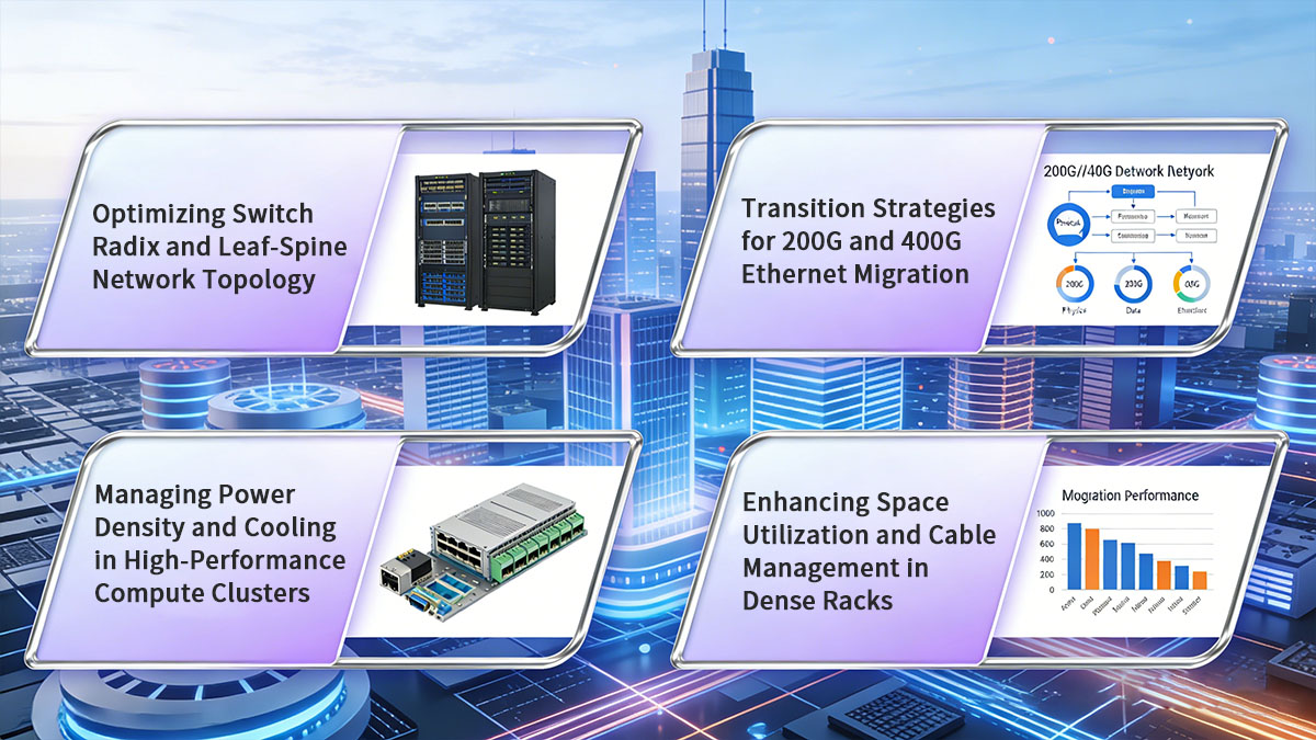
Optimizing Switch Radix and Leaf-Spine Network Topology
QSFP28-DD significantly increases switch radix by doubling the available bandwidth per port without increasing port size. This allows switches to support more high-speed connections, which is essential in leaf-spine architectures where high port counts and uniform bandwidth are critical. Higher radix reduces the number of switches required, simplifying network design and lowering capital expenditure.
In leaf-spine topologies, QSFP28-DD enables more efficient east-west traffic flow by providing higher aggregate bandwidth between layers. This improves overall network performance and reduces latency bottlenecks. As a result, data centers can scale horizontally with fewer tiers while maintaining consistent throughput across the network fabric.
Managing Power Density and Cooling in High-Performance Compute Clusters
As port density and data rates increase, so does power consumption per unit area, making thermal management a key concern. QSFP28-DD modules typically support higher power classes compared to QSFP28, requiring careful planning of airflow and cooling strategies. Efficient thermal design ensures that modules operate within safe temperature ranges, preventing performance degradation.
To address these challenges, data centers implement advanced cooling techniques such as front-to-back airflow optimization, high-efficiency heat sinks, and even liquid cooling in extreme cases. Additionally, system designers must balance power density with rack-level cooling capacity, ensuring that increased performance does not come at the cost of reliability.
Transition Strategies for 200G and 400G Ethernet Migration
QSFP28-DD provides a practical migration path from 100GBASE to 200GBASE and 400GBASE Ethernet by leveraging its 8-lane architecture. Organizations can gradually upgrade their infrastructure by deploying QSFP28-DD ports while still supporting legacy QSFP28 modules. This phased approach minimizes disruption and spreads capital investment over time.
In practice, operators may initially deploy 200G (8×25G NRZ) or 400G (8×50G PAM4) links depending on application requirements. Over time, as demand increases, more ports can transition to higher speeds. This flexibility allows data centers to align network upgrades with workload growth and evolving performance needs.
Enhancing Space Utilization and Cable Management in Dense Racks
High-density QSFP28-DD ports enable more bandwidth per rack unit, improving overall space utilization in data centers. By reducing the number of required ports and switches, operators can free up valuable rack space for additional compute or storage resources. This is especially important in hyperscale environments where physical space is a limiting factor.
At the same time, higher port density introduces challenges in cable management. QSFP28-DD deployments often rely on structured cabling systems and high-density connectors (such as MPO/MTP) to maintain organization and airflow. Proper cable routing, labeling, and management solutions are essential to avoid congestion, ensure maintainability, and support efficient scaling over time.
? Conclusion: Critical Insights into QSFP28-DD Physical Layer Performance
QSFP28-DD represents a significant advancement in high-speed interconnect technology, enabling higher bandwidth, improved port density, and scalable data center architectures. By combining a compact mechanical design with an 8-lane electrical interface, it delivers enhanced performance while maintaining backward compatibility with existing QSFP28 infrastructure.
Key takeaways include:
- Higher Density and Bandwidth: Dual-row contacts enable up to 200G/400G per port without increasing footprint.
- Robust Physical Layer Design: Optimized signal integrity, EMI shielding, and strict compliance standards ensure reliable operation.
- Flexible Deployment: Backward compatibility and CMIS support allow seamless integration with legacy systems.
- Scalability for Hyperscale Environments: Improved switch radix, power efficiency, and space utilization support future growth.
As data center demands continue to evolve, QSFP28-DD provides a future-ready solution for high-performance networking. To explore high-quality QSFP28-DD modules and related solutions, visit the LINK-PP Official Store and discover transceiver modules designed for next-generation data center deployments.


