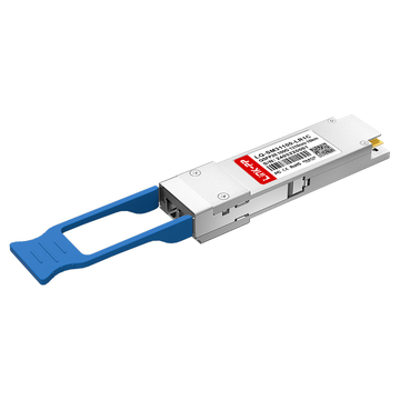
As modern data centers and service providers face skyrocketing demands for bandwidth, upgrading network infrastructure efficiently has become a top priority. To balance performance and budget, many network engineers are turning to third-party alternative transceiver modules as a cost-effective solution. In particular, the QSFP-100G-LR-S Cisco equivalent transceiver has emerged as a go-to choice for high-speed, long-distance optical connectivity.
While OEM optics can be prohibitively expensive, these high-quality compatible transceivers offer identical performance at a fraction of the cost. However, successfully deploying an alternative QSFP-100G-LR-S requires a deep understanding of its technical foundation, including industry standard compliance and precise optical link budgets. This article will break down everything you need to know about this single-lambda 100G QSFP28 module to ensure seamless interoperability in your network.
➡️ Introduction to the QSFP-100G-LR-S Cisco Equivalent Transceiver
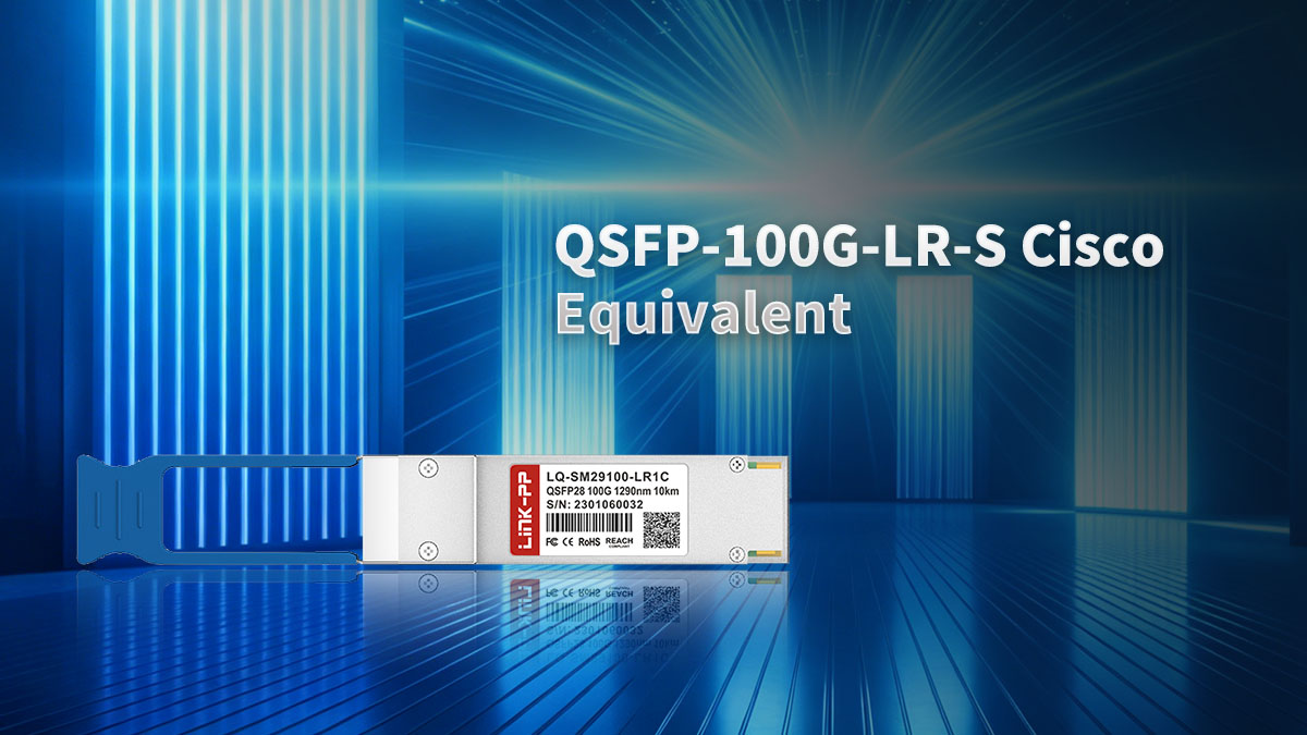
The QSFP-100G-LR-S Cisco equivalent transceiver represents a major shift in how high-speed data travels across long distances. By using advanced optical technology, this compatible module delivers reliable 100G connectivity while drastically lowering hardware costs. Exploring its architecture, physical form factor, and practical applications highlights why it has become an industry standard.
Defining the 100GBASE-LR1 Single-Lambda Architecture
The core innovation of the QSFP-100G-LR-S equivalent lies in its 100GBASE-LR1 single-lambda architecture. Unlike older technology that splits data across multiple lasers, this design transmits the entire 100Gbps data stream over a single wavelength of light. This leap in efficiency simplifies the internal optical components, reducing potential points of failure inside the transceiver.
By consolidating the signal into a single lane, network operators can maximize their fiber efficiency without adding unnecessary complexity. This streamlined approach not only improves long-term reliability but also makes third-party production much more cost-effective. Ultimately, single-lambda architecture provides a cleaner path for high-capacity data transmission.
Core Technical Specifications and the QSFP28 Form Factor
Built on the highly popular QSFP28 form factor, the QSFP-100G-LR-S equivalent easily plugs into standard high-density switches and routers. It operates over standard single-mode fiber (SMF) using a duplex LC connector interface and can reach distances up to 10km. This compact size allows network administrators to save valuable rack space while scaling up their bandwidth.
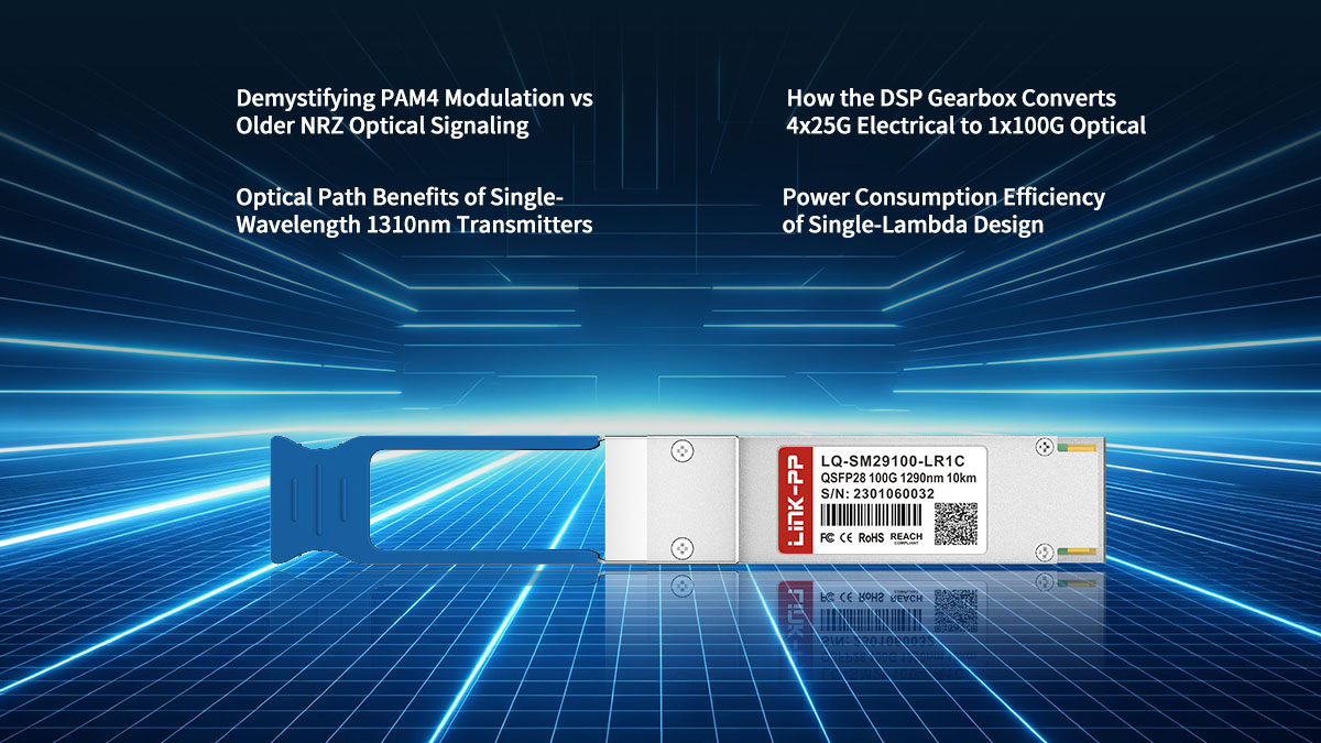
On the electrical side, the module interfaces with the host system using four 25Gbps lanes. An internal digital signal processor (DSP) then handles the heavy lifting by converting these electrical signals for the single optical lane. This seamless compatibility ensures that third-party modules fit perfectly into existing hardware slots without requiring physical modifications.
Target Use Cases in Modern Service Provider and Data Center Networks
The QSFP-100G-LR-S Cisco equivalent is primarily designed to handle campus backbone connections and long-distance data center interconnects (DCIs). Its ability to span 10km makes it ideal for linking geographically separated enterprise facilities or regional network hubs. Third-party alternatives are particularly favored in these environments to scale up capacity without inflating infrastructure budgets.
Service providers also deploy these compatible modules within their metro access networks to handle skyrocketing mobile and broadband traffic. They offer a highly reliable solution for connecting edge routing platforms to core transport networks. By opting for these equivalent transceivers, operators can aggressively expand their network footprints while maintaining strict cost control.
➡️ Understanding 100GBASE-LR1 Technology in the QSFP-100G-LR-S Equivalent
Achieving 100Gbps transmission over a single wavelength requires a sophisticated combination of advanced signaling techniques and specialized hardware. The QSFP-100G-LR-S Cisco equivalent relies on cutting-edge modulation and processing to overcome the physical limits of older optical standards. Examining these foundational technologies reveals how these compatible modules achieve such impressive performance and efficiency.
Demystifying PAM4 Modulation vs Older NRZ Optical Signaling
Traditional 100G transceivers rely on Non-Return-to-Zero (NRZ) signaling, which transmits a single bit of data per optical pulse using simple on-and-off states. To hit higher speeds without multiplying the physical hardware, the QSFP-100G-LR-S equivalent upgrades to Four-Level Pulse Amplitude Modulation (PAM4). By utilizing four distinct voltage levels, PAM4 successfully packs two bits of data into every single signal pulse.
This technological evolution doubles the data density while keeping the optical baud rate completely manageable. The following table highlights the key differences between these two signaling methods to illustrate why PAM4 has become essential for single-lane 100G transmission.
| Feature | NRZ Signaling | PAM4 Modulation |
| Bits Per Symbol | 1 bit | 2 bits |
| Signal Levels | 2 levels (High / Low) | 4 levels (0, 1, 2, 3) |
| Lanes for 100G | Requires 4 optical lanes | Requires 1 optical lane |
| Bandwidth Efficiency | Lower efficiency | Higher efficiency |
How the DSP Gearbox Converts 4x25G Electrical to 1x100G Optical
The host network switch communicates with the QSFP-100G-LR-S compatible transceiver using an electrical interface composed of four separate 25Gbps NRZ lanes. To bridge the gap between this host system and the single-wavelength fiber, the module relies on an internal Digital Signal Processor (DSP) with built-in gearbox functionality. This specialized chip aggregates the incoming traffic and translates the modulation format in real time.
Specifically, the DSP gearbox captures the four 25Gbps NRZ electrical streams and reformats them into a single 53.125 Gigabaud PAM4 optical signal. This precise bidirectional conversion ensures that the host switch receives a familiar electrical interface while the optical link benefits from single-lane efficiency. Without this processing power, third-party modules could not maintain seamless compatibility with legacy switch architectures.
Optical Path Benefits of Single-Wavelength 1310nm Transmitters
By consolidating the entire transmission onto a single 1310nm wavelength, the QSFP-100G-LR-S alternative eliminates the need for complex optical multiplexers and demultiplexers. Older multi-lane designs require intricate prisms to combine and separate distinct optical wavelengths inside the casing. Removing these fragile passive components significantly reduces internal optical loss and lowers the risk of hardware failure.
Furthermore, operating specifically at the 1310nm spectrum offers excellent performance across standard single-mode fiber infrastructure. This wavelength experiences minimal chromatic dispersion, meaning the light pulses do not easily blur together over long distances. As a result, the clean optical path ensures stable, high-quality signal integrity across the entire 10-kilometer reach.
Power Consumption Efficiency of Single-Lambda Design
Transitioning from a four-laser design down to a single-laser architecture yields substantial improvements in energy efficiency. Because a third-party QSFP-100G-LR-S transceiver only has to power and cool one laser transmitter, its raw thermal footprint is noticeably minimized. This reduction in power consumption is a massive operational benefit for high-density network environments.
While the sophisticated DSP chip does draw some power to process the PAM4 signaling, the overall power savings remain highly favorable compared to legacy 100G architectures. Lower power consumption directly translates to reduced heat generation within data center racks, easing the burden on cooling systems. Consequently, choosing single-lambda QSFP-100G-LR-S Cisco equivalents helps operators lower both their upfront hardware costs and ongoing utility bills.
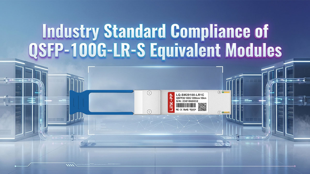
➡️ Industry Standard Compliance of QSFP-100G-LR-S Equivalent Modules
To ensure seamless network integration, third-party compatible transceivers must adhere to strict international engineering regulations. Strict compliance guarantees that a QSFP-100G-LR-S equivalent performs identically to an original Cisco module across diverse hardware environments. Examining these industry standards highlights how these optical modules achieve universal interoperability and safe, reliable operation.
IEEE 802.3cu Clause 140 Regulatory Framework Alignment
The mechanical and optical foundations of the QSFP-100G-LR-S compatible transceiver are governed by the IEEE 802.3cu standard. Specifically, Clause 140 defines the strict regulatory framework for 100Gbps operation over single-mode fiber using single-wavelength technology. This industry-wide mandate ensures that third-party modules meet identical physical and behavioral benchmarks as brand-name optics.
Adhering to this standard guarantees that the module can successfully talk to any other compliant 100GBASE-LR1 device, regardless of the brand. It regulates critical factors like signal timing, wavelength tolerances, and overall transmitter quality. For network engineers, this strict alignment eliminates compatibility guesswork during multi-vendor hardware deployments.
100G Lambda MSA Single-Lane Optical Specifications
Beyond broad IEEE standards, the QSFP-100G-LR-S alternative strictly follows the guidelines set by the 100G Lambda Multi-Source Agreement (MSA). This industry consortium specifically developed the detailed blueprint for single-lane 100G optical transmissions using advanced PAM4 modulation. By adhering to these MSA guidelines, third-party manufacturers can precisely replicate the optical performance of OEM modules.
The MSA specifications dictate exact parameters for optical lane spacing, transmitter behavior, and receiver testing methodologies. This deep level of technical conformity ensures that the signal remains clean and recognizable over the entire 10km link. Ultimately, following these shared multi-vendor specs is what allows compatible modules to deliver plug-and-play reliability.
SFF-8636 and SFF-8665 Management Interface Standards
Internal communications between the host switch and the transceiver rely on specific industry management standards. The QSFP-100G-LR-S equivalent fully complies with SFF-8665, which defines the physical, electrical, and mechanical parameters of the QSFP28 plug. Meanwhile, the SFF-8636 standard outlines the memory map structure utilized by the module's internal microchip.
This dual compliance enables Digital Optical Monitoring (DOM) functionality, allowing network administrators to track real-time health data. Operators can monitor live metrics like operating temperature, laser bias current, and received optical power directly from the switch CLI. This ensures that third-party modules provide the exact same diagnostic visibility as original Cisco equipment.
Laser Safety and Environmental Certification Compliance (RoHS/CE/FDA)
Every high-quality QSFP-100G-LR-S equivalent must pass rigorous international safety and environmental certifications before deployment. Because these modules utilize high-intensity 1310nm lasers, they must meet FDA radiation performance standards and Class 1 laser safety criteria. This certification ensures that the optical output remains completely safe for human eyes under normal operating conditions.
On the environmental front, compliant modules strictly follow the Restriction of Hazardous Substances (RoHS) directive to minimize toxic electronic waste. They also carry CE markings, proving they satisfy strict European health, safety, and environmental protection requirements. These rigorous certifications guarantee that third-party optics are physically safe for both your personnel and the planet.
➡️ Optical Link Budget Specifications for QSFP-100G-LR-S Equivalents
Calculating and maintaining a proper optical link budget is essential for preventing data loss over long-distance single-mode fiber runs. The QSFP-100G-LR-S equivalent must operate within strict power tolerances to guarantee a clean, uninterrupted signal across its entire 10km range. Understanding these precise optical boundaries ensures that third-party transceivers function reliably under real-world networking conditions.
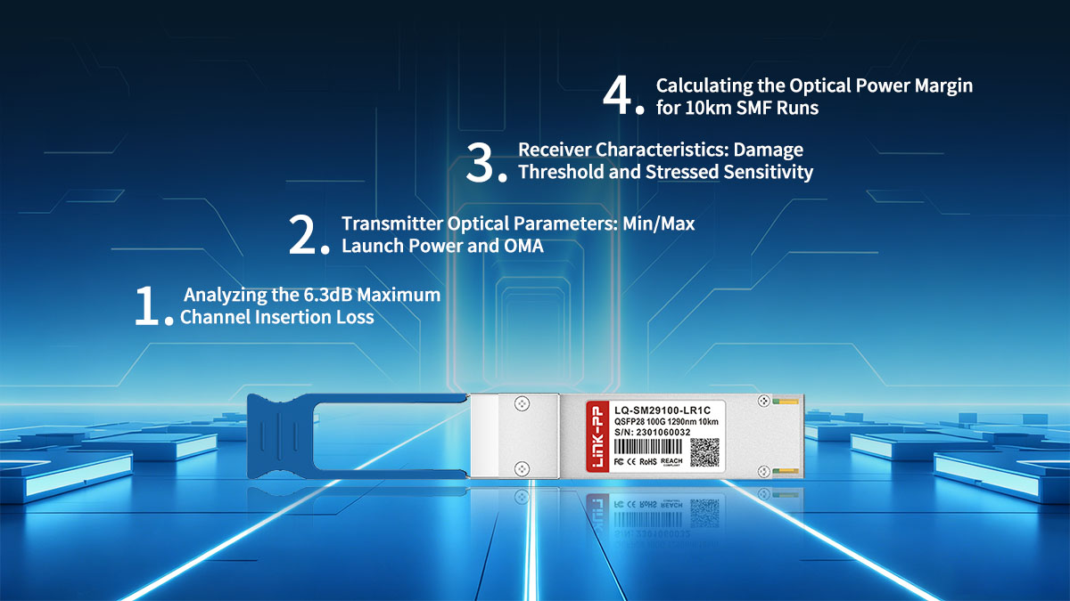
Analyzing the 6.3dB Maximum Channel Insertion Loss
The total signal loss between the transmitting laser and the receiving sensor must never exceed 6.3dB. This maximum channel insertion loss budget represents the total amount of signal degradation that the light path can tolerate before data errors occur. Network engineers must carefully map out every component along the fiber path to ensure they stay safely within this threshold.
Key factors that contribute to this overall insertion loss budget include:
- Fiber Attenuation: The natural degradation of light as it travels through standard single-mode glass fiber, typically averaging around 0.35dB per kilometer at a 1310nm wavelength.
- Connection Points: The signal loss introduced by physical fiber connections, including patch panels, wall outlets, and mechanical splices along the optical path.
- Fusion Splices: The microscopic imperfections created when permanently fusing two fiber optic cables together, which generally introduce a minor loss of 0.1dB or less per splice.
Transmitter Optical Parameters: Min/Max Launch Power and OMA
The optical transmitter inside the QSFP-100G-LR-S compatible module must push out an incredibly precise amount of light into the fiber core. If the transmitter is too weak, the signal will fade before reaching its destination, but if it is too strong, it can blind or damage the receiving hardware. Furthermore, because this module utilizes PAM4 modulation, tracking the average power alone is not enough to guarantee performance.
Critical transmitter metrics that dictate overall link health include:
- Maximum Launch Power: The upper limit of average optical energy the laser is allowed to emit to prevent overwhelming the network equipment on the other end.
- Minimum Launch Power: The absolute lowest amount of light energy required to ensure the signal can successfully clear initial connection losses.
- Optical Modulation Amplitude (OMA): The measurement of the actual power difference between the shifting signal levels of the PAM4 waveform, which directly dictates how cleanly the receiver can read individual data bits.
Receiver Characteristics: Damage Threshold and Stressed Sensitivity
The receiving sensor of a third-party QSFP-100G-LR-S module must be highly sensitive yet robust enough to handle fluctuating optical power levels. It must accurately distinguish between the four distinct light levels of the incoming PAM4 signal, even after the light has traveled through miles of fiber. Evaluating receiver performance requires looking closely at both its physical limits and its operational sensitivity.
Important receiver specifications that protect link integrity include:
- Damage Threshold: The absolute maximum optical power level the receiver can physically tolerate before the incoming laser causes permanent hardware damage to the internal photodiode.
- Stressed Receiver Sensitivity: The lowest optical power level at which the receiver can successfully decode a degraded, noisy signal while maintaining an acceptable bit error rate.
- Saturation Power: The upper limit of normal operational power, beyond which the receiver becomes overloaded and can no longer accurately read incoming data streams.
Calculating the Optical Power Margin for 10km SMF Runs
Before deploying a compatible QSFP-100G-LR-S transceiver on a 10-kilometer link, engineers must calculate the remaining optical power margin. This calculation ensures that the system has enough leftover signal strength to handle unexpected network changes over time. A healthy power margin prevents spontaneous link drops and guarantees long-term operational stability.
The essential steps for establishing a safe optical power margin include:
- Determine Total Cable Loss: Multiply the physical length of the fiber run by its specific attenuation rate to find the total loss caused by the glass itself.
- Sum All Component Losses: Add up the individual insertion losses from all connectors, adapters, and fusion splices present along the entire fiber run.
- Deduct for Aging and Repairs: Subtract an extra 1.0dB to 2.0dB safety buffer to account for future fiber degradation, dust accumulation, or emergency cable splices.
➡️ Fiber Infrastructure Requirements for QSFP-100G-LR-S Equivalent Deployments
The physical glass cabling laying the foundation of your network directly impacts the success of a 100G deployment. Even the most advanced compatible transceivers cannot overcome a poorly planned or dirty fiber optic plant. Choosing the right fiber type and enforcing strict maintenance habits are necessary steps to keep a QSFP-100G-LR-S equivalent operating at peak performance.
Standard Single-Mode Fiber (SMF) Selection: G.652 vs G.657
Selecting the correct single-mode fiber standard is a crucial first step when preparing for a QSFP-100G-LR-S alternative deployment. Traditional networks rely heavily on G.652 fiber, which offers excellent performance across long, straight outdoor runs but suffers from signal loss when tightly bent. In contrast, newer G.657 fiber features a bend-insensitive design that allows cables to twist safely inside tight data center cabinets.
Understanding the unique physical and operational differences between these two common fiber standards helps prevent accidental signal degradation during installation. The following table provides a direct comparison of their primary characteristics to guide your infrastructure choices.
| Feature | G.652 Single-Mode Fiber | G.657 Single-Mode Fiber |
| Primary Advantage | Industry standard, low-cost | Bend-insensitive design |
| Ideal Environment | Long-haul, outdoor conduits | High-density data centers |
| Bend Tolerance | Sensitive to tight macrobends | Maintains signal at tight angles |
| Compatibility | Fully backward compatible | Interoperable with G.652 glass |
Duplex LC Connector Interface and Polishing Standards (UPC vs APC)
The QSFP-100G-LR-S compatible transceiver utilizes a standard duplex LC connector interface to link with your optical patch cables. However, engineers must pay close attention to the polishing style of the fiber ferrules inside those connectors. Mixing up different connector styles can cause massive signal reflections, instantly disrupting the high-speed optical path.
Most enterprise applications utilize Ultra Physical Contact (UPC) blue connectors, which feature a flat, rounded tip that maximizes core alignment. For highly sensitive systems, Angled Physical Contact (APC) green connectors feature an eight-degree slant that forces reflected light into the cable cladding. Because these two end-face geometries do not match, you must never plug an APC connector directly into a standard UPC transceiver port.
The Impact of Fiber Attenuation and Chromatic Dispersion at 1310nm
Operating at a 1310nm wavelength gives the QSFP-100G-LR-S equivalent an inherent advantage because this spectrum sits right at the zero-dispersion point of standard single-mode glass. Chromatic dispersion occurs when different wavelengths of light travel down the fiber at different speeds, causing pulses to blur together over time. Because dispersion is nearly non-existent at 1310nm, the digital PAM4 signals remain sharp and legible over the entire 10km span.
While dispersion is minimal, the signal must still fight against regular fiber attenuation, which slowly saps the laser's power. Attenuation at 1310nm is slightly higher than at 1550nm, generally removing about 0.35dB of power per kilometer of glass. Network operators must track this loss rate closely to ensure the cumulative signal drop stays well below the transceiver's maximum limit.
Best Practices for Cleaning and Testing High-Speed Optical Fiber
Maintaining absolute cleanliness is the most critical factor when working with single-lane PAM4 optics like the QSFP-100G-LR-S alternative. Because the entire 100G stream passes through a single microscopic fiber core, a lone speck of dust can completely block the light or cause fatal back-reflections. Technicians should always follow the strict industry mantra of "inspect, clean, and inspect again" before mating any optical connection.
Using an industrial fiber inspection microscope allows teams to verify that both the cable tip and the transceiver port are free from oils and debris. For effective cleaning, specialized dry-cleaning tools or lint-free wipes soaked in high-purity optical solvent should be used. Once cleaned, a final pass with an optical power meter or an Optical Time-Domain Reflectometer (OTDR) ensures the link meets strict performance standards.
➡️ Forward Error Correction (FEC) Requirements for QSFP-100G-LR-S Equivalents
High-speed single-lambda PAM4 links rely on advanced mathematical algorithms to maintain flawless data transmission over long distances. Because PAM4 signaling features smaller margins between voltage states, it is naturally more susceptible to minor background noise. Enforcing strict Forward Error Correction (FEC) settings on the host hardware ensures that a QSFP-100G-LR-S equivalent can identify and fix packet drops on the fly.
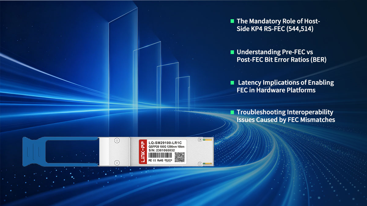
The Mandatory Role of Host-Side KP4 RS-FEC (544,514)
Operating a QSFP-100G-LR-S compatible transceiver requires enabling Reed-Solomon Forward Error Correction, specifically the KP4 RS-FEC (544,514) algorithm. This specific math protocol injects redundant error-correcting data directly into the outbound transmission stream at the switch or router level. Without this mandatory feature active on the host device, the single-lane PAM4 signal will fail to stabilize over the 10km link.
The KP4 algorithm acts like an automated quality control system that continuously sweeps the line for digital corruption. It allows the receiving hardware to detect and repair data blocks that were scratched or distorted by environmental noise. Relying on this host-side math is what allows third-party modules to achieve standard single-mode fiber reaches without needing massive, hot-running lasers.
Understanding Pre-FEC vs Post-FEC Bit Error Ratios (BER)
Evaluating the health of a single-lambda link requires tracking two distinct metrics: Pre-FEC and Post-FEC Bit Error Ratios. The Pre-FEC BER counts the raw volume of digital mistakes occurring in the glass before the mathematical correction algorithm steps in. Because PAM4 signaling is highly sensitive, a relatively high Pre-FEC error rate is normal and expected on a 10km run.
The ultimate goal of the system is to achieve a Post-FEC BER of less than 1 in 10 to the power of negative 12, which represents a totally clean link. This secondary reading measures the remaining uncorrected errors after the host chip has finished processing the data streams. If your Post-FEC count climbs above zero, it indicates that the underlying fiber path is too degraded for the algorithm to fix.
Latency Implications of Enabling FEC in Hardware Platforms
While turning on host-side FEC is necessary for signal stability, processing these data validation algorithms introduces a tiny amount of time delay. The switch hardware must take a brief moment to calculate the mathematical parity blocks before sending or reading packets. For the vast majority of enterprise applications and data center connects, this minor latency penalty is completely unnoticeable.
However, in ultra-low-latency environments like high-frequency financial trading networks, every microsecond of processing lag matters. Network planners must balance the physical reach advantages of the QSFP-100G-LR-S alternative against this minor processing overhead. In most cases, the immense cost savings and structural simplicity of single-lambda architecture far outweigh the tiny latency addition.
Troubleshooting Interoperability Issues Caused by FEC Mismatches
The most common reason a third-party QSFP-100G-LR-S module fails to link up with an existing switch port is an improper FEC configuration. If one side of the fiber link has KP4 FEC active while the opposing hardware platform has it turned off, the devices cannot decode each other's traffic. This mismatch results in a dead port status, even if the optical power monitors show perfect light levels.
Fixing this problem requires manually logging into the Command Line Interface (CLI) of both host switches to verify their port configurations. Technicians must ensure that the port settings match perfectly across the entire link, forcing KP4 operation on both ends. Double-checking this administrative configuration resolves most multi-vendor interoperability issues right out of the box.
➡️ Summary of Compliance and Link Budgets for the Cisco QSFP-100G-LR-S Equivalent
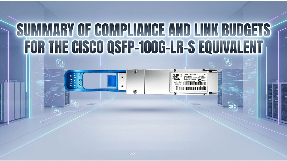
Deploying a third-party QSFP-100G-LR-S compatible transceiver provides an exceptional balance of performance, strict regulatory compliance, and significant infrastructure cost savings. By strictly adhering to single-lambda 100GBASE-LR1 standards and managing a precise 6.3dB optical link budget, network operators can confidently scale up their bandwidth. Ensuring proper fiber maintenance and matching your host-side KP4 FEC configurations creates a rock-solid, multi-vendor environment ready for long-distance data transmission.
If you are looking to upgrade your network infrastructure with reliable, fully compatible optical solutions, finding a trusted hardware manufacturer is key. Discover high-quality, pre-tested optical transceivers and network components designed for seamless interoperability by visiting the LINK-PP Official Store. Their industry-compliant modules deliver premium performance at a fraction of OEM prices, allowing you to scale your data center or service provider network efficiently.