
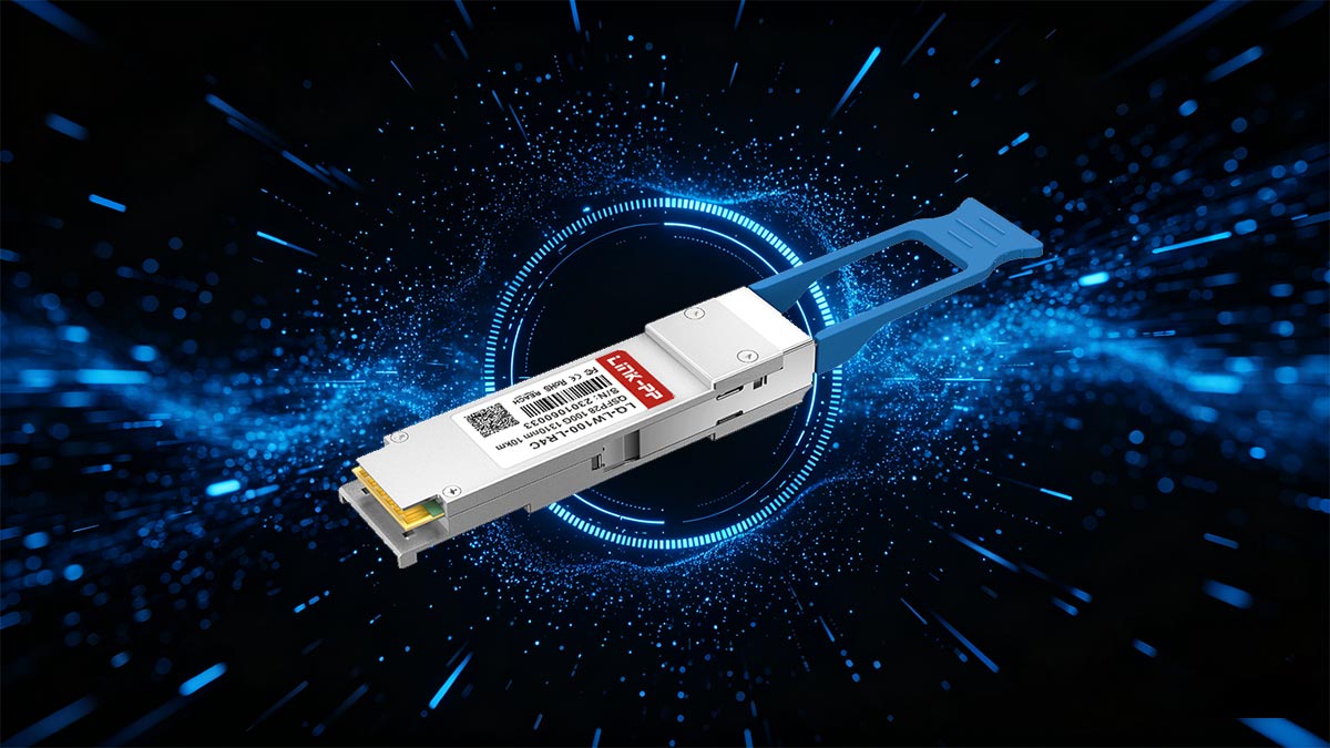
As 100G Ethernet becomes the backbone of data centers, telecom networks, and enterprise infrastructure, understanding the capabilities of different optical standards is essential. Among them, 100GBASE-LR4 stands out as a proven long-reach solution designed for high-speed transmission over single-mode fiber (SMF) up to 10 km.
100GBASE-LR4 is based on a QSFP28 form factor and uses a duplex LC connector, making it widely compatible with modern switching and routing platforms. Its core technology relies on 4×25G LAN Wavelength Division Multiplexing (WDM), where four optical signals are transmitted simultaneously over different wavelengths in the O-band (around 1310 nm). This multi-lane design enables stable, high-capacity data transmission while maintaining strong interoperability across vendors.
Compared with newer single-lambda 100G optics, LR4 represents a mature and standardized architecture that has been widely deployed in long-distance applications. It remains a reliable choice for scenarios that require consistent performance over extended fiber links, such as data center interconnects, campus networks, and metro aggregation.
However, understanding 100GBASE-LR4 is not just about knowing the basic definition. Network engineers and system designers often need clarity on key aspects such as:
- Supported transmission distance and fiber type
- Optical parameters like power levels and link budget
- Differences between LR4 and other 100G standards such as LR, DR, FR, and CWDM4
- Compatibility considerations in real deployments
This guide provides a complete breakdown of 100GBASE-LR4 specifications, helping you understand both the technical details and how they translate into real-world network design decisions.
🟠 What Is 100GBASE-LR4?
Before diving into detailed specifications, it is important to clearly understand what 100GBASE-LR4 is and how it works at a fundamental level. This helps establish a solid foundation for interpreting its parameters and comparing it with other 100G optical standards.
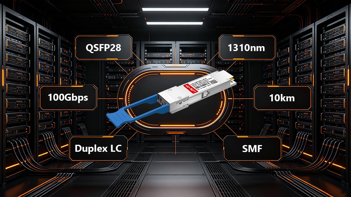
100GBASE-LR4 is a 100 Gigabit Ethernet optical transceiver standard designed for long-range transmission up to 10 km over single-mode fiber (SMF). It is typically implemented in a QSFP28 form factor and uses a duplex LC connector, making it a widely supported solution across modern switches and routers.
At its core, 100GBASE-LR4 achieves 100G data transmission by using four parallel optical lanes, each carrying approximately 25 Gbps. These lanes are combined using LAN Wavelength Division Multiplexing (LAN WDM), allowing all four signals to travel over a single pair of fibers.
Wavelength Structure (LAN WDM)
The four optical lanes operate in the O-band, each assigned a specific wavelength:
- 1295.56 nm
- 1300.05 nm
- 1304.58 nm
- 1309.14 nm
This wavelength multiplexing enables efficient use of fiber while maintaining signal integrity over long distances.
Naming Meaning: LR4 Explained
The term “LR4” reflects the key characteristics of the standard:
- LR (Long Reach): Supports transmission distances up to 10 km
- 4: Uses four optical lanes (4×25G architecture)
This naming convention distinguishes LR4 from other variants such as DR (500 m), FR (2 km), or CWDM4 (2 km with different wavelength spacing).
Core Technology Overview
100GBASE-LR4 uses a 4×25G NRZ modulation scheme combined with electro-absorption modulated lasers (EML). This architecture is known for its:
- High stability over long distances
- Mature ecosystem and interoperability
- Compatibility with standard single-mode fiber (G.652)
Unlike newer single-lambda 100G technologies, LR4 does not rely on complex PAM4 modulation, which simplifies signal processing in many deployments.
In real-world networks, 100GBASE-LR4 is commonly used in:
- Data Center Interconnect (DCI): Connecting facilities across campuses or metro areas
- Enterprise Campus Backbones: High-speed aggregation between buildings
- Telecom and Metro Networks: Reliable long-distance 100G transport
Because it operates over duplex LC SMF, it can be deployed using existing fiber infrastructure without requiring specialized cabling systems.
🟠 100GBASE-LR4 Specifications at a Glance
After understanding the basic concept of 100GBASE-LR4, the next step is to look at its core specifications in a clear, structured format. This section provides a quick-reference overview of the most important parameters, allowing engineers and buyers to evaluate compatibility, performance, and deployment suitability at a glance.
Key Specifications Table
| Parameter |
100GBASE-LR4 Specification |
| Form Factor |
QSFP28 |
| Aggregate Data Rate |
103.125 Gbps |
| Lane Rate |
4 × 25.78125 Gbps |
| Wavelengths (LAN WDM) |
1295.56 nm, 1300.05 nm, 1304.58 nm, 1309.14 nm |
| Transmission Distance |
Up to 10 km |
| Fiber Type |
Single-Mode Fiber (SMF, G.652) |
| Connector Type |
Duplex LC/UPC |
| Laser Type |
EML (Electro-absorption Modulated Laser) |
| Modulation Format |
NRZ (Non-Return to Zero) |
| Power Consumption |
Typically 3.5 W – 4.5 W |
| Operating Temperature |
0°C to 70°C (Commercial), -40°C to 85°C (Industrial) |
| Diagnostics |
DDM / DOM (Digital Diagnostics Monitoring) |
| Standards Compliance |
IEEE 802.3ba, QSFP28 MSA |
How to Read These Specifications
Each parameter above directly impacts real-world deployment:
- Form factor and connector determine physical compatibility with switches and cabling
- Wavelengths and lane structure define how data is transmitted over fiber
- Distance and fiber type indicate whether the module fits your link requirements
- Power consumption and temperature affect system design and reliability
- Diagnostics (DDM/DOM) provide visibility into optical performance for monitoring and troubleshooting
This structured overview is designed to give a complete yet quickly scannable snapshot of 100GBASE-LR4, making it easier to compare with other 100G optical standards in the following sections.
🟠 Optical Parameters and Link Budget Explained
Understanding the specification table is only part of the picture. To determine whether a 100GBASE-LR4 module will actually work in your network, you need to interpret its optical parameters in practical terms. This section translates key datasheet values into real-world deployment guidance so you can quickly evaluate fiber compatibility and link reliability.
Key Optical Parameters
1. Launch Power (Transmit Power)
Launch power refers to the optical signal strength emitted by the transmitter on each lane.
- Typical range: -4.3 dBm to +4.5 dBm (per lane)
- What it means:
This is how strong the signal is when it leaves the module. A higher launch power helps the signal travel longer distances, but it must stay within safe limits to avoid overloading the receiver.
Deployment insight: If your fiber link includes patch panels, connectors, or splices, sufficient launch power ensures the signal can still reach the receiver after losses.
2. Receiver Sensitivity
Receiver sensitivity defines the minimum optical power required for the receiver to correctly detect the signal.
- Typical value: ≤ -8.6 dBm (OMA, per lane)
- What it means:
If the received signal drops below this level, errors will increase and the link may fail.
Deployment insight: This sets the lower limit of your acceptable signal after all losses are accounted for.
3. Receiver Overload
Receiver overload is the maximum optical power the receiver can handle without distortion.
- Typical value: +4.5 dBm (per lane)
- What it means:
If the signal is too strong (for example, in very short links), it can saturate the receiver and cause errors.
Deployment insight: For short-distance connections (e.g., <1 km), you may need optical attenuators to prevent overload.
Link Budget: The Most Important Practical Metric
The link budget represents the total optical loss that a system can tolerate while still maintaining a reliable connection.
How Link Budget Works
In simple terms:
Link Budget = Maximum allowable signal loss between transmitter and receiver
This loss includes:
- Fiber attenuation (distance-related loss)
- Connector losses
- Patch panel losses
- Splice losses
Example Calculation For a 100GBASE-LR4 link:
- Fiber attenuation (10 km SMF): ~3.5 dB
- Connector + patch panel loss: ~1.5 dB
- Total estimated loss: ~5.0 dB
Since this is within the 6.3 dB budget, the link should operate reliably.
Practical Deployment Guidelines
To ensure a stable 100GBASE-LR4 link:
- Keep total link loss below 6.3 dB
- Avoid excessive connectors or poor-quality splices
- Use attenuators for very short links if needed
- Monitor optical levels using DDM/DOM diagnostics
- Always leave a safety margin (e.g., 1 dB) for aging and environmental changes
Why This Matters
These optical parameters are not just theoretical values—they directly determine whether your link will:
- Work reliably
- Experience intermittent errors
- Fail completely
By understanding launch power, sensitivity, overload, and link budget, you can confidently evaluate whether 100GBASE-LR4 is suitable for your specific fiber infrastructure, avoiding costly deployment issues and troubleshooting later.
🟠 100GBASE-LR4 vs. LR, DR, FR, and CWDM4
After understanding the specifications and optical behavior of 100GBASE-LR4, the next step is to compare it with other common 100G optical standards. In real deployments, choosing the right module is not just about speed—it depends on distance, architecture, cost, and compatibility.
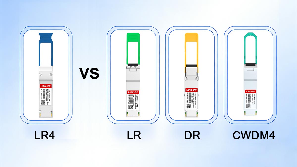
The most important distinction to understand is this:
100GBASE-LR4 uses a 4-wavelength (4×25G) WDM design for 10 km reach, while newer LR/DR/FR modules are typically single-wavelength (single-lambda) solutions, and CWDM4 is a shorter-reach 4-wavelength alternative.
Comparison Overview
| Standard |
Reach |
Technology |
Wavelength Design |
Connector |
Typical Use Case |
| 100GBASE-LR4 |
10 km |
4×25G NRZ |
4 wavelengths (LAN WDM) |
Duplex LC |
Long-range SMF links |
| 100GBASE-LR (LR1) |
10 km |
PAM4 |
Single wavelength (~1310 nm) |
Duplex LC |
Newer 10 km deployments |
| 100GBASE-DR |
500 m |
PAM4 |
Single wavelength (~1310 nm) |
Duplex LC |
Data center interconnect (short reach) |
| 100GBASE-FR |
2 km |
PAM4 |
Single wavelength (~1310 nm) |
Duplex LC |
Campus / short metro links |
| 100GBASE-CWDM4 |
2 km |
4×25G NRZ |
4 wavelengths (CWDM grid) |
Duplex LC |
Cost-effective short reach |
LR4 vs. LR (LR1): Same Distance, Different Technology
Although both support 10 km transmission, LR4 and LR are fundamentally different:
- LR4:
- Uses 4 separate wavelengths (4×25G NRZ)
- Mature and widely deployed
- Does not rely on PAM4 modulation
- LR (LR1):
- Uses single-lambda PAM4 (1×100G)
- Requires more advanced signal processing
- Increasingly used in newer platforms
Key takeaway: They are not interoperable, even though the distance is the same.
LR4 vs. DR and FR: Distance Defines the Choice
- 100GBASE-DR (500 m): Designed for short intra-data-center links
- 100GBASE-FR (2 km): Suitable for campus or short metro connections
- 100GBASE-LR4 (10 km): Built for longer-distance backbone or inter-building links
Key takeaway: If your link exceeds 2 km, LR4 becomes the practical standard option.
LR4 vs. CWDM4: Same Multi-Lane Concept, Different Reach
Both LR4 and CWDM4 use 4-lane WDM architectures, but with different goals:
- LR4:
- Uses LAN WDM wavelengths (tighter spacing)
- Supports up to 10 km
- Higher cost, longer reach
- CWDM4:
- Uses CWDM wavelength grid (wider spacing)
- Supports up to 2 km
- More cost-effective for short links
Key takeaway: Choose CWDM4 for cost-sensitive short links, and LR4 for extended distance.
Practical Selection Guidelines
When choosing between these standards:
- Select LR4 when you need reliable 10 km transmission over SMF
- Choose LR (LR1) for newer systems optimized for single-lambda PAM4
- Use DR or FR for shorter distances (≤2 km)
- Opt for CWDM4 when cost is critical and distance is within 2 km
Why This Comparison Matters
In real-world deployments, many connectivity issues come from incorrect module selection or compatibility assumptions. Understanding these differences helps you:
- Avoid interoperability problems
- Optimize cost vs. performance
- Ensure your optical modules match your network architecture
By clearly distinguishing LR4 from LR, DR, FR, and CWDM4, you can make confident, deployment-ready decisions based on actual network requirements rather than just datasheet labels.
🟠 Compatibility, FEC, and Deployment Notes
After comparing 100GBASE-LR4 with other standards, the next critical step is ensuring it will work correctly in your actual network environment. Many real-world issues are not caused by the module itself, but by compatibility mismatches, incorrect expectations about FEC, or overlooked deployment details.
This section focuses on practical guidance to help you avoid common pitfalls.
Compatibility: What Works and What Does Not
The most important rule is:
100GBASE-LR4 must connect to another LR4 module using the same standard.
Even if two modules share the same connector (duplex LC) and fiber type (SMF), they are not necessarily interoperable.
Common Compatibility Mistakes
- LR4 vs. LR (LR1):
Not compatible — different architectures (4-lane WDM vs. single-lambda PAM4)
- LR4 vs. CWDM4:
Not compatible — different wavelength grids and optical design
- LR4 vs. DR / FR:
Not compatible — different modulation and signaling methods
Key takeaway: Matching form factor (QSFP28) and connector (LC) is not enough. The optical standard must match exactly.
Host-Side Expectations
Even when using the correct module type, the switch or router must support LR4 optics.
What to Check on the Host Device
- Port compatibility: Ensure the port supports 100G QSFP28 LR4
- Vendor support / coding: Some platforms require vendor-approved or coded modules
- Power budget: LR4 modules typically consume 3.5W–4.5W, which may matter in high-density systems
- Firmware / OS version: Older firmware may not fully support certain optics
Practical tip: If a module is not recognized, check the device logs or DOM readings before assuming hardware failure.
FEC (Forward Error Correction): What You Need to Know
FEC behavior is a common source of confusion.
- 100GBASE-LR4 (NRZ, 4×25G): Typically does not require mandatory FEC for operation
- Newer single-lambda optics (LR, DR, FR): Usually require RS-FEC due to PAM4 modulation
If you connect different module types or misconfigure FEC:
- The link may fail to come up
- You may see high bit error rates (BER)
- Performance may be unstable
Practical tip: Always verify whether FEC is enabled, disabled, or auto-negotiated on your switch ports, especially when mixing environments.
Deployment Best Practices
To ensure a smooth 100GBASE-LR4 deployment:
- Use matched LR4 modules on both ends
- Confirm switch compatibility and firmware support
- Verify optical power levels via DDM/DOM
- Keep total link loss within the ~6.3 dB budget
- Add attenuators if needed for very short links
- Clean and inspect all fiber connectors before installation
Troubleshooting Checklist
If your LR4 link is not working:
- Confirm both ends use 100GBASE-LR4 modules
- Check fiber type (SMF) and polarity (Tx/Rx alignment)
- Verify optical power levels are within range
- Inspect connectors for contamination or damage
- Review switch logs and DOM readings
- Check FEC settings and port configuration
In practice, most deployment issues come down to compatibility assumptions or overlooked configuration details. By understanding how LR4 interacts with your hardware, fiber plant, and system settings, you can:
- Avoid costly downtime
- Reduce troubleshooting time
- Ensure stable, long-term performance
This practical awareness turns specification knowledge into real-world reliability, which is ultimately what matters in any 100G deployment.
🟠 Common Applications of 100GBASE-LR4
With its 10 km reach over single-mode fiber (SMF) and duplex LC interface, 100GBASE-LR4 is designed for scenarios where distance, stability, and interoperability are critical. Its 4×25G WDM architecture makes it especially suitable for environments that require reliable long-range connectivity without changing existing fiber infrastructure.
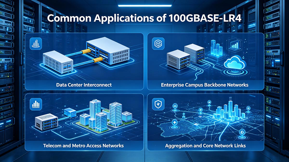
Below are the most common real-world applications where 100GBASE-LR4 is widely deployed.
♦ Data Center Interconnect (DCI)
One of the primary use cases for 100GBASE-LR4 is connecting multiple data centers across campuses or metro areas.
- Supports distances up to 10 km, ideal for inter-building or inter-campus links
- Uses duplex LC SMF, compatible with existing fiber infrastructure
- Provides stable, high-capacity links for data replication, backup, and workload migration
Why LR4 fits: It delivers the reach needed for DCI without requiring more complex coherent optics.
♦ Enterprise Campus Backbone Networks
Large enterprise environments often need high-speed connectivity between buildings.
- Connects core switches across office campuses
- Supports long-distance aggregation links between distribution layers
- Works over standard G.652 single-mode fiber
Why LR4 fits: Its 10 km capability ensures coverage across large campuses while maintaining simple LC connectivity.
♦ Telecom and Metro Access Networks
In telecom environments, 100GBASE-LR4 is commonly used on the client side of transport networks.
- Connects routers and switches to optical transport systems
- Used in metro aggregation and access layers
- Supports stable transmission over typical metro distances
Why LR4 fits: It provides a cost-effective long-reach solution without requiring specialized DWDM systems.
♦ Aggregation and Core Network Links
As networks scale, aggregation layers require higher bandwidth over longer distances.
- Links aggregation switches to core routers
- Supports high-throughput traffic consolidation
- Enables scalable 100G backbone infrastructure
Why LR4 fits: Its combination of distance and reliability makes it suitable for backbone-level connections.
♦ Cross-Building and Industrial Deployments
In environments such as industrial parks, smart campuses, or large facilities:
- Connects buildings separated by several kilometers
- Operates across outdoor SMF infrastructure
- Supports extended temperature variants when required
Why LR4 fits: It offers robust long-distance performance using standard fiber and simple connectivity.
Why 100GBASE-LR4 Remains Widely Used
Across all these scenarios, the key advantages remain consistent:
- Up to 10 km reach over standard SMF
- Duplex LC interface for easy deployment
- Mature, interoperable technology
- Reliable performance in long-distance applications
These characteristics make 100GBASE-LR4 a practical choice for any network that requires dependable 100G connectivity beyond short-reach limits, without adding unnecessary complexity.
🟠 How to Choose the Right 100G Optical Module
After reviewing specifications and comparisons, the final step is making the right selection for your specific network scenario. Choosing a 100G optical module is not just about speed—it depends on distance, cost, architecture, and device compatibility. This section provides a simple, practical decision guide.
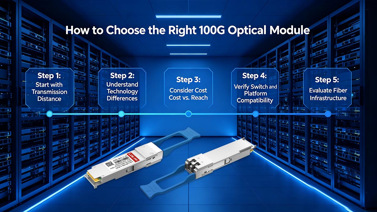
Step 1: Start with Transmission Distance
Distance is the most important factor when selecting a 100G module:
- Up to 500 m → Choose 100GBASE-DR
- Up to 2 km → Choose 100GBASE-FR or CWDM4
- Up to 10 km → Choose 100GBASE-LR4 or LR (LR1)
Key point: If your link requirement approaches or exceeds 10 km, 100GBASE-LR4 is the standard and reliable choice.
Step 2: Understand Technology Differences
Not all 100G modules use the same signaling method:
- LR4 / CWDM4:
- 4×25G NRZ (multi-lane WDM)
- Mature and widely compatible
- LR (LR1) / DR / FR:
- Single-lambda PAM4
- Higher efficiency, newer technology
Selection insight:
- Choose LR4 if you prefer proven stability and interoperability
- Choose single-lambda optics if your platform is optimized for PAM4 and newer architectures
Step 3: Consider Cost vs. Reach
Cost often increases with reach and complexity:
- DR / FR: Lower cost, short reach
- CWDM4: Balanced cost for up to 2 km
- LR4: Higher cost, but supports up to 10 km
Practical rule: Avoid over-specifying. If your link is only 500 m, LR4 is unnecessary. If your link is 8–10 km, shorter-reach modules will not work reliably.
Step 4: Verify Switch and Platform Compatibility
Before purchasing any module, always confirm:
- The port supports QSFP28 100G optics
- The device explicitly supports LR4 or the chosen standard
- Vendor compatibility requirements (coded vs. third-party modules)
- Power and thermal limits for high-density deployments
Important: Even if two modules look identical physically, they must match the same optical standard to function correctly.
Step 5: Evaluate Fiber Infrastructure
Your existing fiber plant also influences the decision:
- Single-mode fiber (G.652): Required for LR4, LR, DR, FR, CWDM4
- Connector type: Typically duplex LC
- Link loss: Must fit within the module’s link budget (~6.3 dB for LR4)
Tip: Check fiber quality, connector cleanliness, and total attenuation before deployment.
Final Recommendation
- Choose 100GBASE-LR4 → When you need stable 10 km transmission over SMF
- Choose 100GBASE-CWDM4 → When distance is ≤2 km and cost matters
- Choose 100GBASE-DR / FR → For short-reach, high-density data center links
- Choose 100GBASE-LR (LR1) → For modern single-lambda deployments (10 km)
If your network requires long-distance 100G connectivity with proven reliability and broad compatibility, 100GBASE-LR4 remains one of the safest and most widely supported choices.
By aligning your selection with distance, platform capability, and deployment environment, you can ensure optimal performance while avoiding unnecessary cost or compatibility issues.
🟠 FAQs About 100GBASE-LR4 Specifications
1. What is 100GBASE-LR4?
100GBASE-LR4 is a 100 Gigabit Ethernet optical transceiver standard designed for up to 10 km transmission over single-mode fiber (SMF). It uses a QSFP28 form factor, a duplex LC connector, and transmits data using four 25G LAN WDM wavelengths over a single fiber pair.
2. What is the difference between 100GBASE LR and LR4?
The key difference is the transmission architecture:
- 100GBASE-LR4: Uses 4×25G WDM (four wavelengths)
- 100GBASE-LR (LR1): Uses single-wavelength PAM4 (1×100G)
Although both support similar distances (up to 10 km), they are based on different optical technologies and are not directly compatible.
3. What is the difference between 100GBASE-DR and 100GBASE-FR?
The main difference is reach and target deployment:
- 100GBASE-DR: Supports up to 500 m, mainly for intra-data center links
- 100GBASE-FR: Supports up to 2 km, for campus or short metro links
Both use single-lambda PAM4 modulation, but FR extends the reach through improved optical design.
4. What is the difference between 100GBASE CWDM4 and 100GBASE LR4?
Both use four-wavelength WDM technology, but they target different distances:
- CWDM4: Designed for up to 2 km cost-optimized links
- LR4: Designed for up to 10 km long-reach connections
LR4 uses tighter LAN WDM spacing, while CWDM4 uses a broader CWDM grid, making it more cost-efficient for shorter distances.
5. What connector does 100GBASE-LR4 use?
100GBASE-LR4 uses a duplex LC/UPC connector. This is a widely adopted fiber connector type that supports separate transmit and receive fibers for full-duplex communication over single-mode fiber.
6. What fiber type is required for LR4?
100GBASE-LR4 requires single-mode fiber (SMF), typically ITU-T G.652 compliant fiber. Multimode fiber is not supported, as LR4 is designed specifically for long-distance transmission over low-loss single-mode infrastructure.
🟠 Conclusion: When 100GBASE-LR4 Is the Right Choice
100GBASE-LR4 remains one of the most widely deployed and trusted solutions for long-reach 100G optical connectivity. Its combination of 10 km transmission distance, duplex LC interface, and 4×25G LAN WDM architecture makes it a stable and standards-based option for modern high-speed networks.
In practical deployment terms, LR4 is the right choice when you need:
- Reliable 100G transmission over single-mode fiber up to 10 km
- A solution that works with existing duplex LC SMF infrastructure
- A mature and widely interoperable optical standard
- Predictable performance without moving to more complex coherent systems
Unlike newer single-lambda solutions, LR4 continues to be valued for its proven stability, broad compatibility, and straightforward integration into enterprise, telecom, and data center environments.
Explore Compatible Solutions
If your network design requires long-distance 100G connectivity with minimal complexity and strong ecosystem support, 100GBASE-LR4 remains a safe and practical choice. It balances performance, reach, and compatibility in a way that continues to meet real-world deployment needs.
For more detailed specifications, compatible optical modules, and deployment options, you can explore the full product range and technical resources at the: LINK-PP Official Store
This provides additional datasheets, compatibility guidance, and optical module options to help you match the right solution to your specific network requirements.


