
The SFP LC connector has become the industry standard for high-density networking, primarily due to its compact "Small Form Factor" (SFF) design. By utilizing a 1.25mm ferrule, the LC connector effectively halves the space required compared to older SC interfaces, allowing for significantly higher port density on SFP and SFP+ transceiver modules. This space efficiency is critical for modern data centers and telecommunications hubs where maximizing rack space is a top priority.
Beyond its physical footprint, the SFP LC connector is defined by rigorous mechanical and optical standards. Its push-pull latching mechanism ensures secure connections and easy handling, while strict adherence to IEC and TIA/EIA specifications guarantees interoperability across diverse hardware. This article explores the precision engineering, standardized dimensions, and performance factors that make the SFP LC connector an indispensable component in reliable, high-speed fiber optic infrastructures.
🎋 SFP LC Connector Overview and Key Features
The SFP LC connector serves as a critical interface in modern fiber optic communications, specifically engineered to support the high-density requirements of small form-factor pluggable modules. It combines a miniaturized physical footprint with robust mechanical latching to ensure stable and high-performance optical connectivity.
Definition and Basic Structure of SFP LC Connector
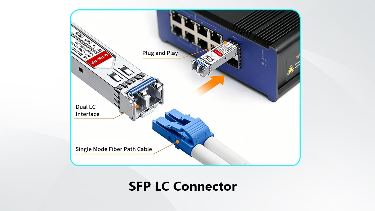
An SFP LC connector refers to the combination of an SFP (Small Form-factor Pluggable) module and an LC (Lucent Connector) fiber interface. The LC connector features a small form factor with a 1.25mm ferrule, approximately half the size of traditional SC connectors, allowing for higher port density. Structurally, it includes a connector housing, ferrule, alignment sleeve, latch mechanism, and fiber cable, all designed to ensure precise optical alignment and stable signal transmission.
Typical Use Cases in Networking Equipment
Due to its compact size, the SFP LC connector is the primary interface for SFP, SFP+, and XFP transceiver modules. You will commonly find these connectors in high-density data center switches, enterprise routers, and fiber-to-the-home (FTTH) central office equipment. It is also extensively used in Storage Area Networks (SAN) and high-speed telecommunications backbones where multiple fiber links must be terminated within a limited rack space (U-space).
Advantages Over Other Connector Types
Compared to other fiber optic connectors, the SFP LC connector offers a balanced combination of size, performance, and usability. Its compact design allows for more ports within the same hardware footprint, while its push-pull mechanism simplifies installation and maintenance. Additionally, it provides reliable optical performance suitable for high-speed data transmission.
To better illustrate these benefits, the following table compares SFP LC connectors with other common connector types:
| Feature |
LC Connector |
SC Connector |
ST Connector |
| Ferrule Size |
1.25mm |
2.5mm |
2.5mm |
| Form Factor |
Compact (high density) |
Larger |
Medium |
| Connection Mechanism |
Push-pull |
Push-pull |
Twist-lock |
| Port Density |
High |
Moderate |
Low |
| Suitability for High Speed |
Excellent |
Good |
Limited |
🎋 SFP LC Connector Mechanical Design Principles
The mechanical design of the SFP LC connector is centered on achieving high-precision fiber alignment within a miniaturized architecture. By integrating sophisticated coupling mechanisms and durable materials, the design ensures that optical fibers remain perfectly positioned even under mechanical stress or high-vibration environments.
Compact Form Factor and Space Efficiency
The LC connector’s primary design objective is to minimize the physical footprint without compromising signal integrity. By utilizing a 1.25mm ferrule, the mechanical body is significantly narrower than legacy connectors, allowing it to fit perfectly into the narrow apertures of SFP and SFP+ transceiver modules.
This compact form factor enables "duplex" configurations (two fibers in one housing) that occupy the same space as a single older-style connector. This efficiency is the cornerstone of modern high-density networking, allowing hardware manufacturers to pack up to 48 or even 96 ports into a single rack unit.
Push-Pull Coupling Mechanism
The SFP LC connector uses a push-pull coupling mechanism, which simplifies installation and removal. Users can easily insert or disconnect the connector without the need for additional tools, improving operational efficiency and reducing the risk of handling errors.
This mechanism also provides secure engagement, ensuring that the connector remains firmly seated during operation. The latch design minimizes accidental disconnections and maintains consistent optical contact, which is critical for maintaining signal integrity.
Ferrule Alignment and Precision Engineering
Precision alignment is a core aspect of the SFP LC connector’s mechanical design. The ferrule, typically made with tight tolerances, ensures accurate alignment of the fiber cores to minimize insertion loss and maximize signal transmission efficiency.
Alignment sleeves within the adapter further enhance this precision by guiding the ferrules into exact position during mating. This level of engineering control is essential for high-speed optical networks, where even minor misalignment can significantly impact performance.
Materials Used in Connector Housing
The connector housing of an SFP LC connector is typically made from high-quality thermoplastics or engineered polymers that offer strength, durability, and resistance to environmental factors. These materials help protect internal components while maintaining structural integrity over repeated use.
In some designs, ceramic materials are used for ferrules due to their excellent hardness and low thermal expansion properties. The combination of robust housing and precision materials ensures long-term reliability, even in demanding networking environments.
🎋 SFP LC Connector Interface Dimensions and Tolerances
The performance of an SFP LC connector relies heavily on strict control of its interface dimensions and mechanical tolerances. Even microscopic deviations can lead to fiber misalignment, increased optical loss, or unstable connections. Therefore, standardized dimensions and precision manufacturing are essential to ensure consistent mating performance and signal reliability.
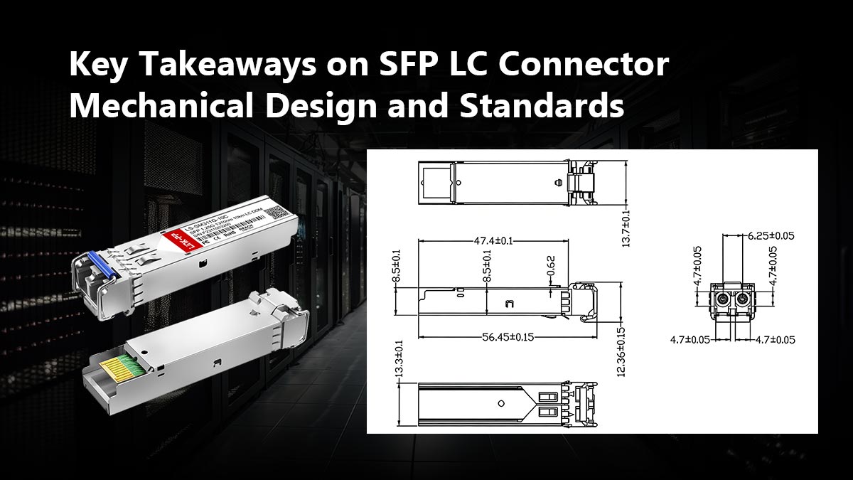
Standardized Connector Dimensions
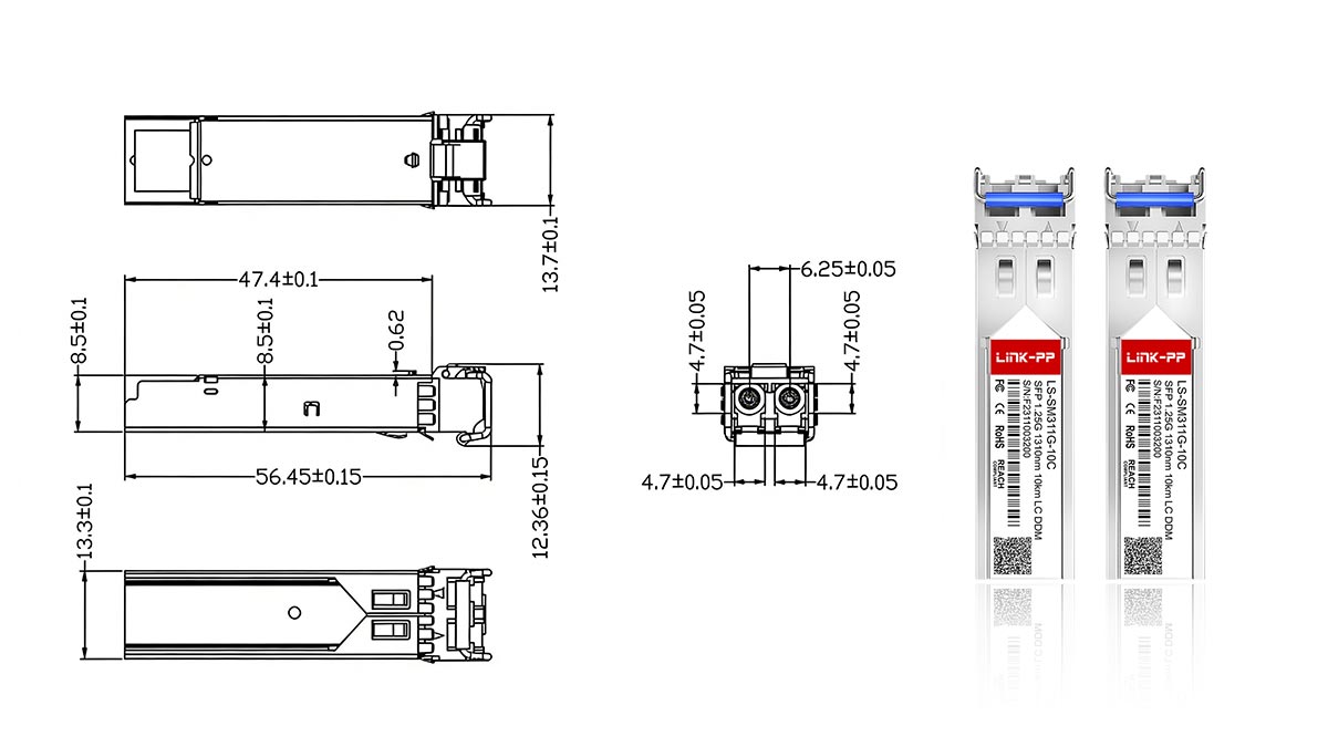
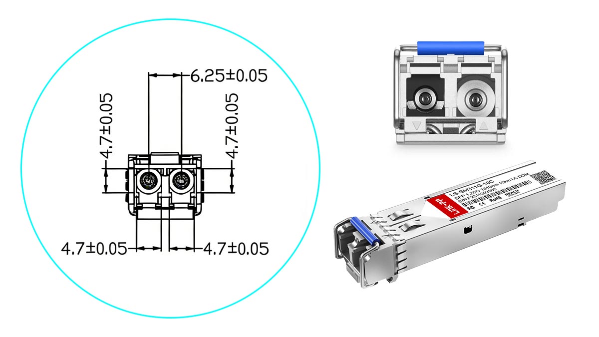
SFP LC connectors are designed in accordance with IEC 61754-20, which defines the physical interface for LC connectors. This standard specifies key parameters such as connector length, latch geometry, ferrule positioning, and duplex clip spacing, ensuring consistent mating across vendors. The duplex LC connector typically maintains a center-to-center spacing of 6.25mm between the two ferrules, enabling compatibility with standard SFP transceiver ports.
In addition, the latch mechanism dimensions are tightly controlled to ensure proper engagement force and retention strength. This prevents accidental disconnection while avoiding excessive insertion force that could damage the transceiver cage or adapter interface.
Ferrule Diameter Specifications
The LC connector uses a 1.25mm diameter ceramic ferrule, with typical manufacturing tolerances within ±1µm. The fiber hole at the center of the ferrule is also precisely drilled, usually around 125µm to match the cladding diameter of standard optical fibers, with sub-micron concentricity tolerance to ensure accurate fiber core positioning.
Surface geometry is another critical factor. The ferrule end-face must meet strict curvature radius (typically 7 - 25mm for UPC) and apex offset requirements to ensure proper physical contact between mated fibers. These parameters directly influence insertion loss and return loss, especially in high-speed transmission scenarios.
Alignment Sleeve Requirements
Alignment sleeves are used within LC adapters to ensure precise alignment between two mating ferrules. These sleeves are typically made from zirconia ceramic or phosphor bronze, chosen for their high dimensional stability and wear resistance. The inner diameter of the sleeve is engineered with micron-level precision to provide a snug fit around the ferrules without excessive friction.
The split-sleeve design allows slight elastic deformation to accommodate minor variations in ferrule diameter while maintaining strong centering force. This ensures that the fiber cores remain aligned within a tolerance of less than 1µm, which is critical for minimizing insertion loss in single-mode applications.
Tolerance Control for Signal Integrity
Tolerance control in SFP LC connectors extends beyond individual components to the entire mated interface. Key parameters such as ferrule concentricity, end-face geometry, and axial alignment must all fall within strict limits to maintain low insertion loss (typically ≤0.3dB) and high return loss (≥50dB for UPC, ≥60dB for APC).
Manufacturers employ precision polishing, automated inspection, and interferometric measurement techniques to verify these tolerances. Any deviation — such as angular misalignment, poor surface finish, or dimensional drift — can introduce back reflection or signal attenuation, which becomes increasingly critical in high-speed networks like 10G, 25G, and beyond.
🎋 SFP LC Connector Compliance with Industry Standards
SFP LC connectors are designed to meet a range of international standards that ensure consistency, reliability, and interoperability across different manufacturers and applications. These standards define mechanical dimensions, optical performance, and testing methods. Compliance is essential for guaranteeing that connectors perform predictably in high-speed and high-density network environments.
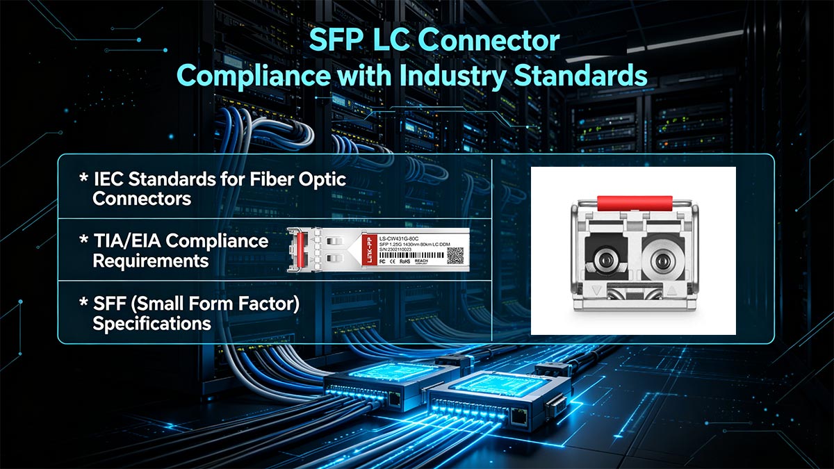
IEC Standards for Fiber Optic Connectors
The International Electrotechnical Commission (IEC) provides key standards governing LC connector design and performance. IEC 61754-20 specifically defines the interface dimensions for LC connectors, including ferrule positioning, mating geometry, and adapter compatibility. This ensures that connectors from different vendors can physically connect without mismatch.
In addition, IEC 61300 series standards outline test and measurement procedures, such as insertion loss, return loss, mechanical durability, and environmental performance. These tests simulate real-world conditions — such as temperature cycling, vibration, and repeated mating — to verify the long-term reliability of SFP LC connectors.
TIA/EIA Compliance Requirements
In North America, SFP LC connectors must comply with standards set by the Telecommunications Industry Association (TIA) and Electronic Industries Alliance (EIA). TIA-568 is one of the most important standards, defining performance requirements for structured cabling systems, including fiber optic connectors.
These standards specify parameters such as allowable insertion loss, return loss thresholds, and connector end-face quality. They also provide guidelines for installation practices and field testing, ensuring that SFP LC connectors maintain consistent performance when deployed in enterprise and data center environments.
SFF (Small Form Factor) Specifications
SFP LC connectors are closely tied to Small Form Factor (SFF) specifications, particularly those defined by the SFF Committee for transceiver modules. The SFF-8074 document, also known as the INF-8074i SFP MSA, defines the fundamental mechanical and electrical requirements for original SFP modules. For higher-speed SFP+ applications, the SFF-8432 specification — also called the Improved Pluggable Formfactor (IPF) standard — specifically defines the mechanical requirements for SFP+ modules and cages, ensuring compatibility with the LC optical interface.
These specifications guarantee that the LC connector aligns precisely with the SFP transceiver port in terms of spacing, insertion depth, and latch engagement. Compliance with SFF standards ensures seamless integration between connectors and transceivers, enabling plug-and-play functionality and reliable operation in multi-vendor network systems.
🎋 SFP LC Connector Optical Performance Factors
The optical performance of an SFP LC connector directly impacts the efficiency and reliability of fiber optic communication. Key parameters such as signal loss, alignment precision, and surface finishing determine how effectively light is transmitted between fibers. Optimizing these factors is essential for maintaining stable performance, especially in high-speed and long-distance applications.
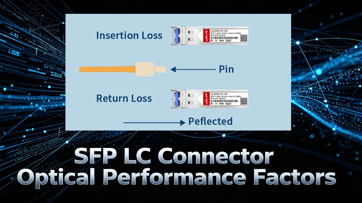
Insertion Loss and Return Loss
Insertion loss and return loss are the two primary metrics used to evaluate connector performance. They reflect how much signal is lost during transmission and how much light is reflected back toward the source.
In practical applications, these parameters are influenced by several factors:
Insertion Loss (IL):
- Typically ≤0.2 - 0.3dB for high-quality LC connectors.
- Caused by fiber misalignment, end-face contamination, or poor polishing.
- Lower IL ensures more efficient signal transmission.
Return Loss (RL):
- ≥50dB for UPC, ≥60dB for APC connectors.
- Affected by end-face geometry and refractive index mismatch.
- Higher RL reduces back reflection, which is critical for laser-based systems.
Maintaining low insertion loss and high return loss is essential for ensuring signal stability and minimizing transmission errors.
Alignment Accuracy and Signal Quality
Precise alignment between fiber cores is fundamental to achieving high signal quality. Even slight lateral, angular, or axial misalignment can significantly degrade optical performance, especially in single-mode fiber systems.
Key alignment factors include:
- Lateral Offset: Directly increases insertion loss when fiber cores are not perfectly centered.
- Angular Misalignment: Causes light scattering and increased back reflection.
- End-face Separation: Leads to Fresnel reflection and signal attenuation.
High-precision ferrules and alignment sleeves are engineered to control these variables within micron-level tolerances, ensuring consistent optical coupling and stable signal transmission.
Impact of Ferrule Polishing Types (UPC/APC)
The polishing type of the ferrule end-face plays a critical role in determining return loss and reflection behavior. The two most common types are UPC (Ultra Physical Contact) and APC (Angled Physical Contact).
Their differences can be summarized as follows:
UPC (Ultra Physical Contact):
- Flat or slightly curved end-face.
- Typical return loss ≥50dB.
- Suitable for general data communication and short-to-medium distances.
APC (Angled Physical Contact):
- End-face polished at an 8° angle.
- Return loss ≥60 dB or higher.
- Minimizes back reflection by deflecting reflected light away from the fiber core.
- Preferred for high-speed, long-distance, and sensitive optical systems.
Choosing the appropriate polishing type depends on the application’s sensitivity to reflection and overall system requirements.
Performance in High-Speed Transmission
As network speeds increase to 10G, 25G, 40G, and beyond, the optical performance requirements for SFP LC connectors become more stringent. High-speed transmission is more sensitive to signal degradation, making connector quality a critical factor.
Several aspects influence performance at higher data rates:
- Bandwidth Support: Requires minimal signal distortion and consistent optical coupling.
- Reflection Control: Critical for preventing noise in high-frequency signals.
- Thermal Stability: Ensures consistent performance under varying operating conditions.
- End-face Cleanliness: Even microscopic contamination can cause significant signal loss at high speeds.
In high-speed environments, well-manufactured SFP LC connectors with tight tolerances and proper maintenance practices are essential to maintain low bit error rates and reliable network performance.
🎋 SFP LC Connector Compatibility and Interoperability
Compatibility and interoperability are critical for ensuring that SFP LC connectors function seamlessly across different devices, vendors, and network architectures. Thanks to strict adherence to mechanical and optical standards, these connectors support plug-and-play deployment in multi-vendor environments. However, achieving optimal performance still depends on matching connector types, fiber specifications, and module requirements.
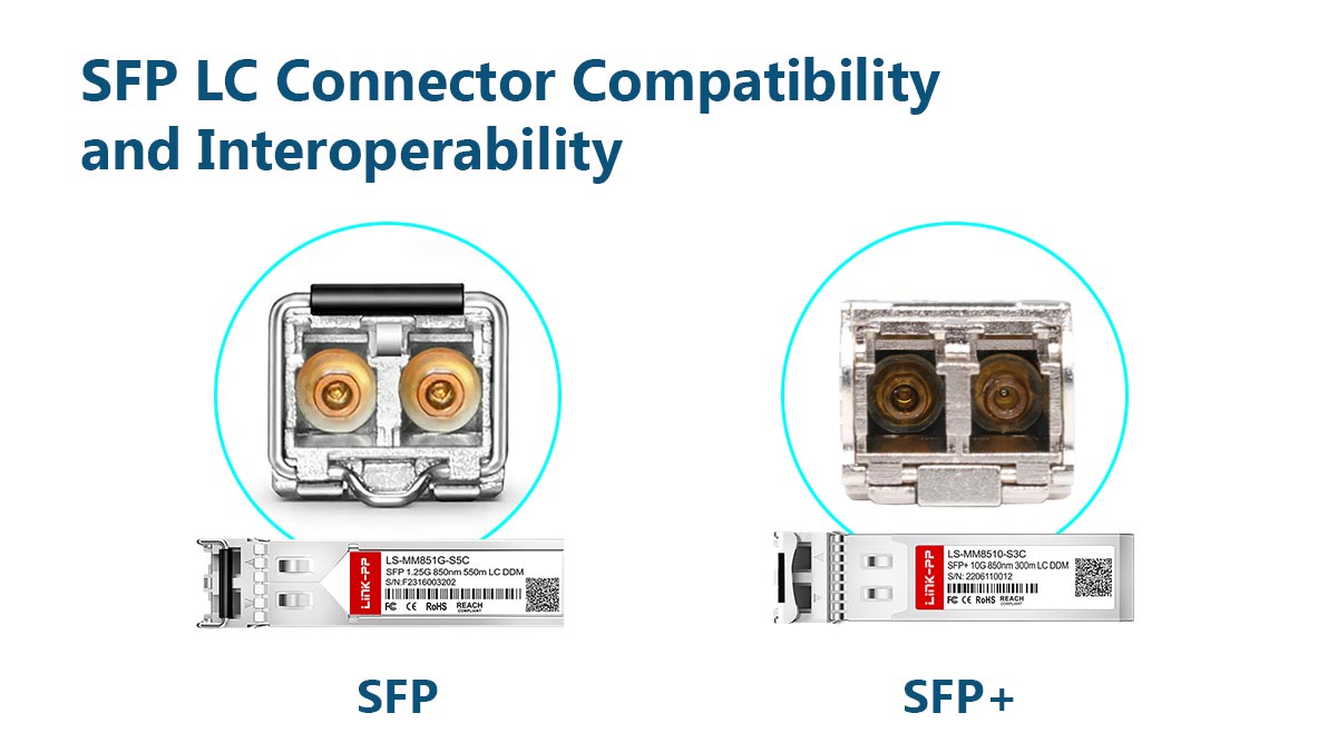
Compatibility with SFP and SFP+ Modules
SFP LC connectors are specifically designed to interface with SFP and SFP+ transceivers, following SFF mechanical specifications such as SFF-8074 and SFF-8432. The LC duplex interface aligns precisely with the transceiver port, including defined insertion depth, latch position, and port spacing, ensuring consistent physical engagement.
In practice, compatibility also depends on matching optical parameters such as wavelength (e.g., 850nm for multimode, 1310nm/1550nm for single-mode) and connector polishing type (UPC or APC). While most SFP/SFP+ modules use UPC interfaces, inserting an APC connector into a UPC port can cause poor physical contact and high return loss, leading to degraded performance or link failure.
Interoperability with Different Fiber Types
SFP LC connectors are designed to support both single-mode and multimode fiber systems, but true interoperability depends on maintaining proper optical matching rather than just physical compatibility. While the LC interface remains identical, differences in core diameter, numerical aperture, and modal behavior can significantly affect signal transmission when mismatched fibers are used.
In practical deployment, several technical factors must be carefully managed:
- Core Size Mismatch: Connecting single-mode fiber (≈9µm core) to multimode fiber (50/62.5µm core) can lead to significant coupling loss and unstable signal propagation, especially over longer distances.
- Modal Dispersion Differences: Multimode fibers support multiple light paths, while single-mode fibers support only one. Mixing them can introduce bandwidth limitations and increased signal distortion.
- Transceiver Compatibility: SFP modules are optimized for specific fiber types (e.g., SX for multimode, LX for single-mode). Using the wrong fiber type with a given module can result in reduced transmission distance or complete link failure.
To ensure reliable interoperability, it is essential to match the fiber type with the appropriate SFP transceiver module and application requirements. In cases where mixed environments are unavoidable, solutions such as mode-conditioning patch cords or wavelength-specific transceivers can help mitigate performance degradation.
Backward Compatibility Considerations
SFP LC connectors maintain backward compatibility with earlier LC-based systems due to consistent adherence to IEC interface standards. This allows newer SFP+ or even SFP28 modules to physically accept existing LC connectors without requiring changes to the cabling infrastructure.
However, backward compatibility does not always guarantee optimal performance. Higher-speed modules impose stricter requirements on insertion loss, return loss, and overall link budget. For example, a legacy LC connector with marginal end-face quality may function in a 1G system but introduce unacceptable signal degradation in a 10G or 25G environment. Therefore, while mechanical compatibility is preserved, upgrading connector quality and ensuring proper certification is often necessary for high-speed deployments.
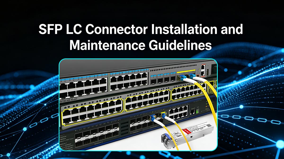
🎋 SFP LC Connector Installation and Maintenance Guidelines
Proper installation and regular maintenance are essential to ensure the long-term performance and reliability of SFP LC connectors. Even with high-quality components, improper handling or contamination can quickly degrade optical performance. Following standardized procedures helps minimize insertion loss, prevent damage, and maintain stable network operation.
Proper Handling and Cleaning Procedures
SFP LC connectors are highly sensitive to dust, oil, and microscopic particles, which can significantly impact signal transmission. Therefore, careful handling and routine cleaning are critical before every connection.
When working with connectors, the following practices should be followed:
- Avoid direct contact with the ferrule end-face: Touching the ferrule can leave oil residues that increase insertion loss and reflection.
- Always use dust caps when connectors are not in use: This prevents airborne contamination from settling on the end-face.
- Clean before every mating: Use lint-free wipes, isopropyl alcohol (≥99%), or dedicated fiber cleaning tools.
- Inspect end-face quality: Use a fiber inspection microscope to verify cleanliness and detect scratches or defects.
Consistent cleaning and inspection significantly reduce the risk of link failures and ensure optimal optical performance.
Installation Best Practices
Correct installation ensures proper mechanical engagement and optimal optical alignment. Although SFP LC connectors are designed for ease of use, improper insertion or cable handling can still cause performance issues.
Key installation guidelines include:
- Ensure correct orientation: Align the LC connector with the SFP port and insert it gently until the latch clicks into place.
- Avoid excessive force: Forcing the connector can damage the ferrule, alignment sleeve, or transceiver interface.
- Maintain proper bend radius: Fiber cables should not be bent beyond their minimum bend radius (typically ≥30mm for standard fiber) to prevent signal attenuation.
- Secure cable routing: Use cable management systems to avoid tension or strain on the connector.
Following these practices helps maintain stable connections and prolong the lifespan of both connectors and transceivers.
Troubleshooting Common Issues
When network performance degrades, SFP LC connectors are often one of the first components to inspect. Many common issues are related to contamination, misalignment, or physical damage.
Typical troubleshooting steps include:
- Check for contamination: Dirty end-faces are the most common cause of high insertion loss — clean and re-test the connection.
- Inspect for physical damage: Look for scratches, chipped ferrules, or loose connectors that may affect alignment.
- Verify proper seating: Ensure the connector is fully inserted and the latch is securely engaged.
- Test with alternative components: Swap cables or transceivers to isolate whether the issue is connector-related.
Systematic troubleshooting helps quickly identify the root cause and restore normal operation.
Preventing Signal Loss and Damage
Preventive measures are critical to maintaining consistent optical performance over time. Small issues such as microbending, connector wear, or repeated contamination can accumulate and degrade signal quality.
To minimize long-term risks, consider the following:
- Limit mating cycles: Frequent insertion and removal can wear out the ferrule and alignment sleeve, reducing precision over time.
- Control environmental conditions: Avoid exposure to excessive dust, humidity, or temperature fluctuations that may affect connector stability.
- Use high-quality components: Certified connectors with tight tolerances provide more consistent performance and durability.
- Implement regular inspection schedules: Periodic testing and cleaning help detect early signs of degradation before they impact the network.
By combining proper handling, correct installation, and proactive maintenance, SFP LC connectors can deliver reliable, low-loss performance in demanding networking environments.
🎋 Key Takeaways on SFP LC Connector Mechanical Design and Standards
SFP LC connectors play a critical role in modern fiber optic networks by combining compact mechanical design with high-precision optical performance. From standardized interface dimensions and strict tolerance control to compliance with IEC, TIA/EIA, and SFF specifications, every aspect of the SFP LC connector is engineered to ensure reliable, low-loss connectivity. Their push-pull mechanism, precise ferrule alignment, and compatibility with a wide range of SFP/SFP+ modules make them a cornerstone of high-density and high-speed network deployments.
Equally important are the optical performance factors and practical considerations discussed throughout this article. Parameters such as insertion loss, return loss, and polishing type directly impact signal quality, while proper installation, cleaning, and maintenance practices are essential for sustaining long-term performance. In increasingly demanding environments like data centers and telecom networks, even minor deviations in connector quality or handling can lead to significant performance degradation.
As network speeds continue to scale, choosing high-quality, standards-compliant SFP LC connectors and transceivers becomes more important than ever. If you are looking for reliable and high-performance optical transceiver solutions, explore the LINK-PP Official Store for a wide range of SFP, SFP+, and other optical modules. LINK-PP transceiver modules are designed with strict quality control and industry compliance, helping you build stable, efficient, and future-ready fiber optic networks.


