
Which 25G DAC should you choose? The SFP-25G-DAC-50cm provides superior signal integrity over the 1-meter variant due to lower insertion loss. Under IEEE 802.3by standards, the shorter 50cm length frequently allows network engineers to run a "No-FEC" (Forward Error Correction) configuration, eliminating up to 250 nanoseconds of latency per hop. However, the 1m cable is often required to navigate standard 19-inch racks without violating the tight minimum bend radius of 30 AWG twinax copper.
When architecting intra-rack Top-of-Rack (ToR) topologies for NVMe-over-Fabrics (NVMe-oF) or High-Frequency Trading (HFT) environments, moving from 10G to 25 Gigabit Ethernet (25GbE) introduces strict physical layer constraints. Unlike legacy SFP+ cables that tolerate lengths up to 7 meters flawlessly, 25G signals operating at higher Nyquist frequencies are highly susceptible to copper insertion loss and electromagnetic interference (EMI).
For network engineers connecting servers equipped with Mellanox ConnectX or Broadcom NICs to switches like the Cisco Nexus series, the choice between an SFP-25G-DAC-50cm (0.5 meters) and a 1-meter Direct Attach Copper (DAC) cable is not merely a matter of physical reach. It is a calculated trade-off between electrical performance, FEC-induced latency, and physical rack management.
Baseline Parameter Comparison: 0.5m vs. 1.0m SFP28 DAC
A Passive DAC is a twinax copper cable with no internal signal amplification components. It relies entirely on the host device to transmit the signal, making physical length the primary variable in signal degradation.
| Specification |
SFP-25G-DAC-50cm (0.5m) |
SFP-25G-DAC-1m (1.0m) |
| IEEE Standard |
802.3by (25GBASE-CR) |
802.3by (25GBASE-CR) |
| Signal Integrity (Insertion Loss) |
Minimal (Excellent Eye Diagram) |
Moderate (Acceptable Eye Diagram) |
| Expected FEC Requirement |
No-FEC or FC-FEC (Base-R) |
RS-FEC (Reed-Solomon) typical |
| FEC Latency Penalty |
~0 ns to 100 ns |
~250 ns per hop |
| Typical Wire Gauge (AWG) |
30 AWG |
30 AWG or 26 AWG |
| Rack Routing Flexibility |
Strict (Requires adjacent U-space) |
Flexible (Allows proper slack loops) |
In the following sections, we will analyze the empirical data behind these parameters, diving deep into how the 50cm length acts as a catalyst for sub-microsecond latency, and examining the real-world deployment challenges regarding OEM EEPROM compatibility and physical bend radii.
🔶 What Is the SFP-25G-DAC-50cm?
What is the Juniper SFP-25G-DAC-50cm? It is a passive 25 Gigabit Ethernet Direct Attach Copper (DAC) cable designed for ultra-short-reach networking. Featuring an SFP28 form factor and a strict 0.5-meter (50 cm) length, this cable is engineered for point-to-point, intra-rack connections. Juniper explicitly classifies it as a 1-to-1 link that is not breakout capable, making it ideal for linking a server directly to an adjacent Top-of-Rack (ToR) switch with near-zero latency.
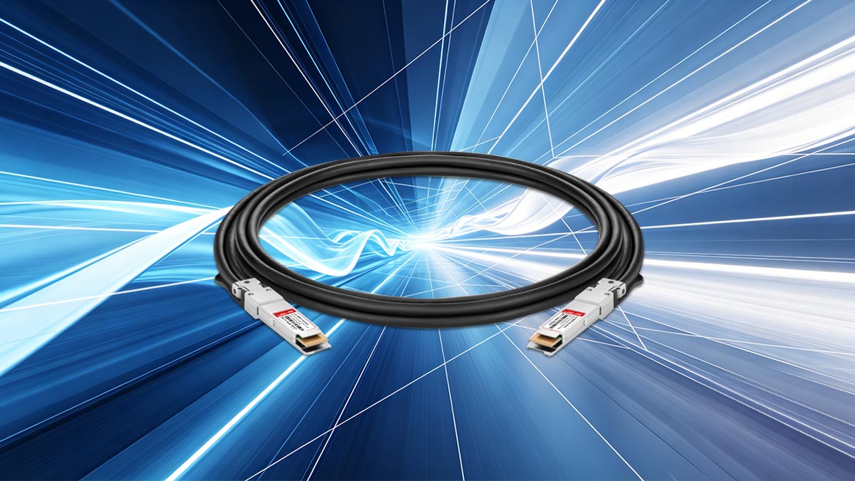
Within the Juniper Networks hardware ecosystem, the SFP-25G-DAC-50cm serves as a foundational interconnect for high-density data centers transitioning from legacy SFP+ 10G architecture to higher throughputs. To understand its precise application, we must deconstruct its core technical identifiers:
- Product Type (DAC): As a Direct Attach Copper cable, it consists of an insulated twinax copper core factory-terminated with transceiver modules on both ends. Because it is a passive DAC (lacking internal signal regeneration chips), it requires virtually zero power (<0.1W) and introduces minimal thermal load into the server rack.
- Form Factor (SFP28): *Micro-Definition: SFP28 (Small Form-factor Pluggable 28) is the standard transceiver footprint for 25G networking. While it shares the exact physical dimensions of older SFP+ (10G) modules, the electrical lanes and shielding are highly engineered to handle 25Gbps signal frequencies cleanly without excessive electromagnetic interference (EMI).
- 25 Gigabit Ethernet: It is fully compliant with IEEE 802.3by standards, guaranteeing 25Gbps data transmission across a single electrical lane, making it highly efficient for modern NVMe storage protocols.
The Non-Breakout, Short-Reach Use Case
Network architects must note that Juniper explicitly flags the SFP-25G-DAC-50cm as not breakout capable. In high-density networking, "breakout" refers to the ability to split a high-capacity switch port (like a 100G QSFP28 port) into four distinct 25G connections via a multi-branch cable. The SFP-25G-DAC-50cm cannot perform this function; it is strictly a 1-to-1 (server-to-switch or switch-to-switch) interconnect.
Furthermore, the 50 cm (roughly 19.6 inches) short-reach designation dictates a highly specific deployment strategy. This cable length is strictly for intra-rack wiring. It is purposefully constrained to connect network hardware that is physically adjacent—typically located within 1 to 2 Rack Units (U) of each other. By minimizing the physical distance the electrical signal must travel, this 50cm cable preserves pristine signal integrity, ensuring a flawlessly open electrical eye diagram at the receiver.
🔶 SFP-25G-DAC-50cm vs. 1m: Core Architectural Differences
What is the architectural difference between a 50cm and 1m 25G DAC? Structurally, both the SFP-25G-DAC-50cm and the 1m variant share the same passive twin-axial copper design and SFP28 transceivers. The core architectural difference lies in the electrical channel length, which directly dictates insertion loss. The 50cm cable offers a significantly lower attenuation profile, preserving a wider electrical eye diagram, whereas the 1m cable sacrifices marginal signal strength in exchange for physical rack-routing flexibility.
Before analyzing their differences, it is crucial to understand what the 50cm and 1m cables share. Both interconnects are governed by the IEEE 802.3by (25GBASE-CR) specification.
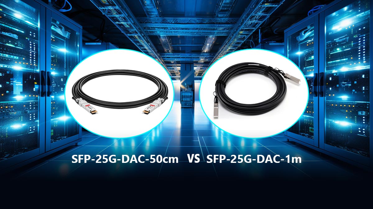
A Passive Architecture dictates that the SFP28 transceiver housing contains no active electronic components—such as Digital Signal Processors (DSPs) or retimers—to amplify the signal. The host device (your switch or Network Interface Card) is solely responsible for driving the high-frequency electrical pulses across the copper medium.
Because both lengths are passive, they operate at an identical, ultra-low power consumption footprint of roughly 0.1 watts per port, making them vastly superior to Active Optical Cables (AOCs) or optical transceivers in ToR (Top-of-Rack) thermal management.
The Divergence: Insertion Loss and Wire Gauge (AWG)
At a base signaling rate of 25.78125 GBd (Gigabaud), electrical signals degrade exponentially faster over copper than older 10G (SFP+) signals. The physical difference of 50 centimeters introduces distinct architectural trade-offs:
- Insertion Loss Margin (The 50cm Advantage): The SFP-25G-DAC-50cm effectively cuts the physical copper resistance in half compared to the 1m version. This inherently reduces electromagnetic interference (EMI) exposure and limits signal attenuation. The result is a highly robust signal at the receiving port, which is the foundational architectural requirement for disabling Forward Error Correction (FEC) for low-latency tuning.
- American Wire Gauge (AWG) Considerations: To mitigate insertion loss, DAC manufacturers must balance wire thickness. A 50cm 25G DAC is almost universally constructed using 30 AWG twinax copper, keeping the cable as lightweight as possible while easily meeting IEEE 802.3by signal thresholds. However, to pass the same rigorous compliance tests over a 1-meter distance, some manufacturers must utilize a thicker 26 AWG or 28 AWG wire. This subtly changes the physical architecture, making the 1m cable marginally heavier and structurally distinct.
Architectural Verdict: The SFP-25G-DAC-50cm is architected purely for electrical perfection over the shortest possible distance, while the 1m DAC represents the architectural baseline where engineers begin compromising slight signal integrity to achieve practical U-to-U rack reach.
🔶 Signal Integrity at 25G: Why Cable Length Matters
Why does length dictate signal integrity in 25G DACs?
Because 25 Gigabit Ethernet operates at a high Nyquist frequency (approximately 12.89 GHz for NRZ encoding), electrical signals suffer from rapid attenuation, skin effect, and crosstalk over twinax copper. The SFP-25G-DAC-50cm significantly reduces the physical transit medium compared to a 1m cable, minimizing insertion loss. This shorter path ensures a pristine signal-to-noise ratio (SNR) and a distinctly wider electrical eye diagram at the receiver.
To appreciate the superiority of the 50cm length, network engineers must look at the physics of Non-Return-to-Zero (NRZ) signaling. During the legacy 10G (SFP+) era, copper cables were highly forgiving; 10Gbps signals could travel up to 7 meters passively without critical degradation.
However, pushing 25.78125 Gbps over a single electrical lane fundamentally changes how the copper behaves. At these frequencies, the copper medium acts almost like a microwave waveguide. Every additional centimeter exacerbates the "skin effect"—where the high-frequency current crowds the outer surface of the conductor, increasing resistance—and dielectric loss.
*Micro-Definition: The Eye Diagram is an oscilloscope display used to measure signal quality. A "wide open" eye indicates strong signal integrity with clear distinctions between 1s and 0s. As cable length increases from 50cm to 1m, insertion loss causes the eye to "close," increasing the probability of bit errors.
The Role of Forward Error Correction (FEC)
Because the IEEE recognized that 25G signals would naturally degrade over copper, the IEEE 802.3by standard mandated the use of algorithms to digitally repair degraded signals at the receiving port.
*Micro-Definition: Forward Error Correction (FEC) is a digital signal processing technique where redundant data is added to the transmitted signal, allowing the receiver to detect and mathematically correct bit errors on the fly without requesting a retransmission.
The physical length of your DAC directly determines the intensity of the FEC required to maintain the industry-standard Bit Error Rate (BER) of \(10^{-12}\). This is where the SFP-25G-DAC-50cm vs. 1m debate is truly settled at the protocol layer:
- RS-FEC (Reed-Solomon FEC): The most computationally heavy correction algorithm. It is highly effective but introduces significant processing latency. 1-meter and 3-meter 25G DACs almost universally require RS-FEC to maintain a stable link.
- FC-FEC (Base-R / Firecode FEC): A lighter algorithm that provides moderate error correction with a lower latency penalty. Short cables often negotiate down to this standard.
- No-FEC (Disabled): The holy grail of ultra-low latency networking. Because the SFP-25G-DAC-50cm suffers such minimal insertion loss, the base signal arrives so cleanly that many high-performance enterprise switches and NICs (such as Mellanox ConnectX series) can safely negotiate a "No-FEC" link while still maintaining a flawless BER.
The Bottom Line on Signal Integrity: Cable length at 25G dictates signal health, and signal health dictates your FEC requirement. By choosing a 50cm DAC over a 1m DAC, you are buying the electrical overhead necessary to downgrade or completely disable Forward Error Correction.
🔶 Latency Showdown: Does 50cm Actually Beat 1 Meter?
Does a 50cm DAC have lower latency than a 1m DAC?
Yes, but not for the reason most assume. The physical transit time difference between 0.5 meters and 1 meter of copper is merely ~2.5 nanoseconds—a negligible margin. The true latency advantage of the SFP-25G-DAC-50cm comes from protocol negotiation. Its superior signal integrity allows network administrators to bypass Reed-Solomon Forward Error Correction (RS-FEC), saving approximately 250 nanoseconds of processing latency per switch hop.
When architects design environments for High-Frequency Trading (HFT), AI cluster synchronization, or NVMe-over-Fabrics (NVMe-oF), "low latency" is the primary mandate. However, a common fallacy in the networking industry is attributing latency solely to the speed of light through a physical medium.
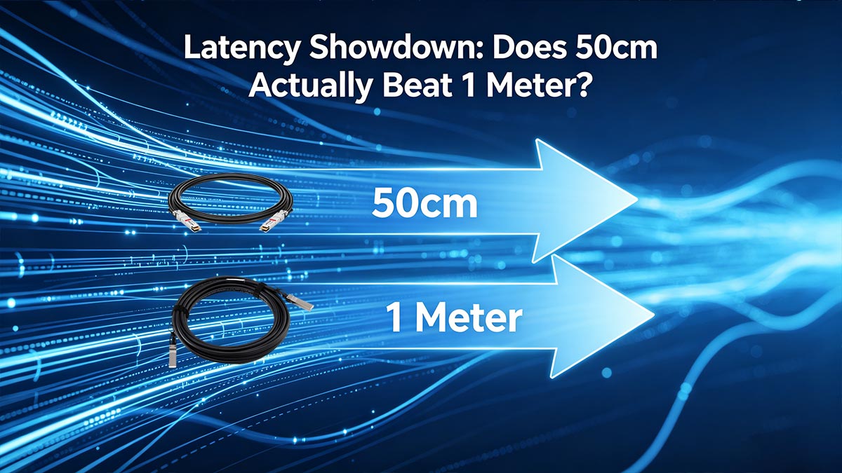
Let us examine the baseline physics: Electrical signals propagate through twinax copper at roughly 70% the speed of light in a vacuum (a Velocity of Propagation, or Vf, of ~0.7c). This equates to approximately 5 nanoseconds of transit time per meter. Therefore, shrinking your cable from 1 meter to 50 centimeters saves a theoretical 2.5 nanoseconds. Even in the most aggressive hyper-converged architectures, 2.5 nanoseconds is statistically invisible.
The Real Latency Culprit: FEC Processing
The true "latency showdown" between the SFP-25G-DAC-50cm and the 1m variant occurs inside the silicon of your Network Interface Card (NIC) and Top-of-Rack (ToR) switch. As established, longer 25G cables require Forward Error Correction (FEC) algorithms to mathematically rebuild degraded signals.
These algorithms require silicon clock cycles to compute, and those clock cycles introduce hard latency penalties.
| FEC Configuration |
Typical Cable Length Support |
Estimated Latency Penalty (Per Hop) |
| RS-FEC (Reed-Solomon) |
Required for 1m to 5m DACs |
~250 ns (Highly impactful) |
| FC-FEC (Base-R) |
0.5m to 3m DACs |
~80 to 100 ns (Moderate impact) |
| No-FEC (Disabled) |
Strictly 0.5m DACs (or shorter) |
0 ns (Zero processing latency) |
If a data packet traverses a leaf-spine architecture passing through three switches, a 1-meter cable using RS-FEC will compound the penalty, adding nearly a full microsecond (750 ns) of latency to the round trip.
The Latency Verdict: Yes, the 50cm DAC beats the 1m DAC in latency. By utilizing the SFP-25G-DAC-50cm, network administrators unlock the ability to safely disable FEC, bypassing the silicon processing penalty entirely and achieving true wire-speed, sub-microsecond latency.
🔶 Rack Routing and Bend Radius: The Hidden 50cm Challenge
Why is deploying a 50cm DAC difficult?
While the SFP-25G-DAC-50cm offers peak electrical performance, its 0.5-meter length often proves physically insufficient for standard EIA-310 19-inch rack geometries. Routing a 50cm cable from a server's peripheral PCIe slot to the opposite side of a Top-of-Rack (ToR) switch leaves virtually no slack. This lack of a service loop frequently forces technicians to violate the cable's minimum bend radius or apply lateral torque to the SFP28 transceiver cages, risking both physical damage and signal degradation.
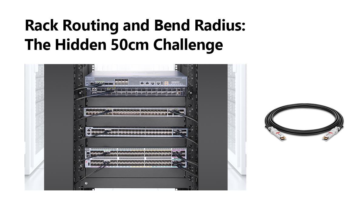
Network architecture is a balance of electrical theory and physical reality. On paper, the 50cm DAC is the optimal choice for latency and signal integrity. In practice, data center technicians frequently cite cable routing as the primary reason for abandoning 50cm cables in favor of the 1-meter variant.
The challenge begins with the physical dimensions of the server chassis. In a standard 19-inch rack, a server's Network Interface Card (NIC) is typically housed in a rear PCIe slot located on the far left or far right of the motherboard. If the corresponding 25G port on the ToR switch is located on the opposite side of the rack, the diagonal distance alone can consume 35 to 40 centimeters of the cable's total reach. This leaves less than 10 centimeters to accommodate cable management arms (CMA), Velcro bundling, and the necessary straight-angle approach into the transceiver ports.
The Physics of Minimum Bend Radius
To maintain high-frequency 25Gbps signal integrity, the SFP-25G-DAC-50cm is heavily shielded, typically utilizing a 30 AWG twinax copper construction. This shielding makes 25G DACs noticeably stiffer than legacy 10G SFP+ cables.
Every twinax cable has a strictly defined minimum bend radius (typically roughly 5 to 10 times the outer diameter of the cable, equating to about 25mm to 30mm for a 30 AWG DAC). When a 50cm cable is stretched too tightly across a rack, it is often kinked or bent sharply at the connector boot to force it into the port. Violating this bend radius yields severe consequences:
- Dielectric Deformation: Sharp bends crush the internal dielectric insulator. This alters the precise physical spacing between the twin copper axes.
- Impedance Mismatch and Return Loss: Altering the twinax spacing changes the cable's differential impedance (which must remain at exactly 100 ohms). This mismatch causes signal reflection (Return Loss), which aggressively closes the electrical eye diagram and increases the Bit Error Rate (BER).
- Mechanical Strain on SFP28 Cages: A taut 50cm cable acts as a lever. It applies lateral torque to the delicate SFP28 cage inside both the NIC and the switch. Over time, this mechanical stress can fracture solder joints on the motherboard or cause micro-disconnects leading to intermittent link flapping.
Deployment Recommendation: The SFP-25G-DAC-50cm should only be provisioned when the server NIC and the ToR switch port are vertically aligned within 1 to 2 Rack Units (U) of each other. If the connection requires horizontal cross-rack routing, upgrading to a 1-meter DAC is a mandatory architectural compromise to ensure proper strain relief and preserve the physical integrity of the transceiver ports.
🔶 OEM Compatibility: Cisco, Ubiquiti, and Mellanox Tips
Does DAC brand matter for 25G compatibility?
Yes. OEM compatibility is dictated by the EEPROM coding within the SFP28 transceiver heads. Enterprise brands like Cisco strictly enforce vendor lock-in and will block ports if generic cables are detected. Conversely, Mellanox (NVIDIA) and Ubiquiti maintain highly permissive transceiver policies. For mixed-vendor environments (e.g., a Mellanox server connecting to a Cisco switch), engineers must utilize custom-coded DACs where each end features specific OEM firmware to ensure seamless link negotiation.
Beyond physical length and signal integrity, the most frequent point of failure in a 25 Gigabit Ethernet deployment is protocol rejection at the port level. The SFP-25G-DAC-50cm is governed by the Multi-Source Agreement (MSA), which standardizes the physical and electrical characteristics of the SFP28 module. However, MSA compliance alone does not guarantee plug-and-play functionality.
*Micro-Definition: Every SFP28 connector contains an EEPROM (Electrically Erasable Programmable Read-Only Memory) chip. This chip broadcasts the cable's serial number, vendor name, and supported protocols to the host device. Network switches read this EEPROM to determine if the hardware is "supported."
Vendor-Specific Deployment Strategies
Understanding how different hardware manufacturers treat third-party EEPROM data is critical for avoiding deployment delays and link-state errors.
- Cisco (Nexus and Catalyst Platforms): Cisco is notorious for strict vendor lock-in. Inserting an uncoded or generic SFP-25G-DAC-50cm will immediately trigger an
%ETHPORT-5-IF_DOWN_UNSUPPORTED_TRANSCEIVER error, placing the port into an err-disabled state. While network administrators can bypass this using the hidden CLI command service unsupported-transceiver, this is strongly discouraged in production environments as it voids Cisco TAC support for that physical layer. Ensure your DAC is explicitly flashed with Cisco-compatible code.
- Mellanox / NVIDIA Networking (ConnectX Series): Mellanox ConnectX-4, ConnectX-5, and ConnectX-6 Network Interface Cards (NICs) represent the gold standard for high-throughput enterprise servers and homelabs. Mellanox firmware is exceptionally open and will accept almost any MSA-compliant generic DAC. The primary focus when connecting Mellanox cards is ensuring the correct FEC (Forward Error Correction) negotiation is set in the OS driver to match the switch.
- Ubiquiti (UniFi Enterprise / Pro Series): Ubiquiti switches (such as the USW-EnterpriseXG-24) maintain a highly permissive transceiver policy. Generic cables typically work flawlessly. However, the challenge with Ubiquiti lies in auto-negotiation. If you attempt to plug an SFP28 25G DAC into an older 10G SFP+ port on a UniFi switch, auto-negotiation often fails. The administrator must manually hardcode the port speed to 10 Gbps in the UniFi Network Controller to establish a link.
The Mixed-Vendor Challenge (Dual-Coding)
Modern intra-rack wiring rarely features homogeneous hardware. It is highly common to connect a Dell or Supermicro server (equipped with a Mellanox NIC) to an Arista or Cisco Top-of-Rack switch.
Because a standard DAC shares the same EEPROM code on both ends, a Cisco-coded cable might be rejected by a finicky server NIC, or vice versa. The professional solution is to source a dual-coded DAC. Specialized third-party optics manufacturers can flash End A with Cisco EEPROM data and End B with Mellanox EEPROM data. This ensures native hardware recognition on both sides of the link, allowing the SFP-25G-DAC-50cm to initialize instantly without throwing syslog errors.
Hardware Procurement Recommendation: Never assume generic MSA compliance is sufficient for Tier-1 enterprise switches. Always map out the endpoint hardware brands prior to purchasing your ToR cabling, and utilize custom-coded EEPROMs to guarantee seamless layer-1 integration and preserve vendor support warranties.
🔶 DAC vs. Fiber: Is Copper Still the Right Choice?
Is copper still relevant for 25G networking?
Yes. For ultra-short intra-rack connections like the SFP-25G-DAC-50cm, passive copper remains the definitive engineering choice. DACs offer significantly lower power consumption, eliminate optical conversion latency, and require a fraction of the capital expenditure (CapEx) compared to optical transceivers. However, fiber optics become the mandatory standard when scaling beyond 3 to 5 meters, navigating complex cross-rack topologies, or implementing structured patching architectures.
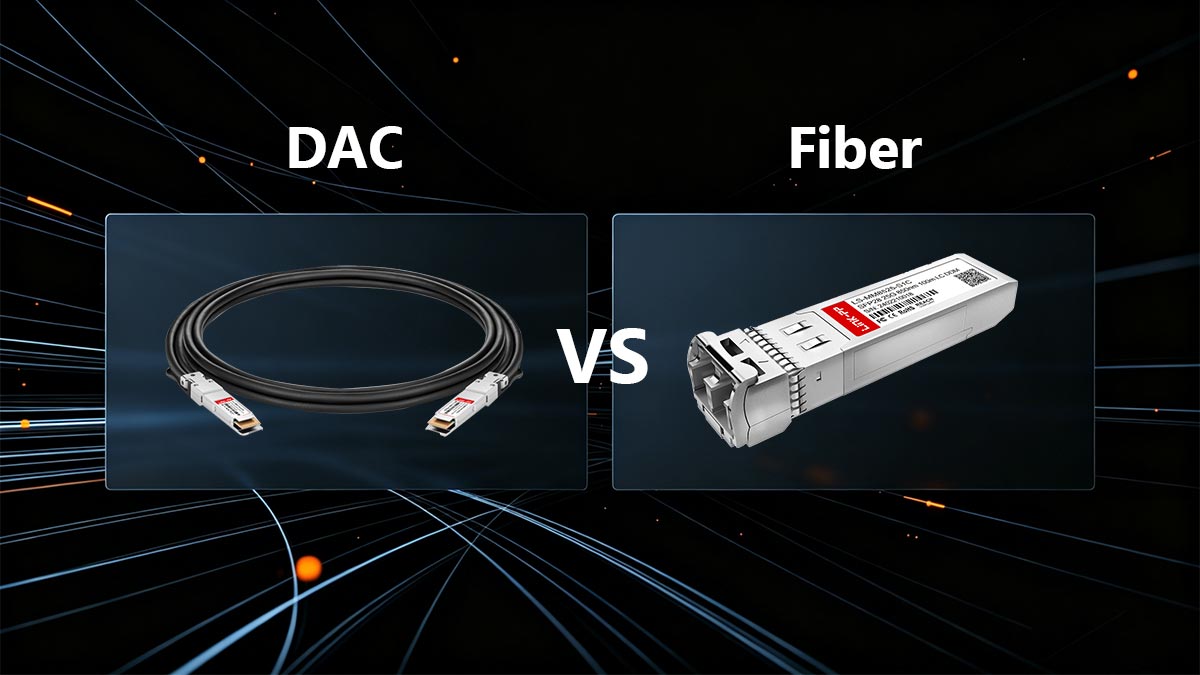
As data centers push toward 100G and 400G backbones, a common misconception is that copper is obsolete at the access layer. While fiber optic technology (such as 25GBASE-SR transceivers paired with OM4 multimode fiber) is undeniably superior for long-haul and inter-rack communication, deploying optics for a 50-centimeter Top-of-Rack (ToR) connection introduces unnecessary physical and financial overhead.
OEO Conversion (Optical-Electrical-Optical) is the physical process required by fiber optic networks where an electrical signal from the switch ASIC is translated into photons by a VCSEL laser, transmitted across the glass fiber, and converted back into electrons at the receiving NIC.
The Architectural Advantages of Passive DAC at 50cm
When evaluating the SFP-25G-DAC-50cm against an equivalent 25G optical link, the passive copper architecture demonstrates three distinct advantages for short-reach deployments:
- Thermal Load and Power Consumption: A standard 25GBASE-SR optical transceiver consumes approximately 1.0 to 1.2 watts of power. Because a fiber link requires two transceivers, a single connection draws over 2.0 watts. In contrast, a passive DAC draws less than 0.1 watts per port. In a fully populated 48-port ToR switch, utilizing DACs saves roughly 100 watts of continuous power draw, significantly reducing the localized thermal footprint and HVAC cooling requirements.
- Absolute Minimum Latency: Because the SFP-25G-DAC-50cm bypasses the OEO conversion process entirely, it avoids the nanosecond latency penalties inherently introduced by optical DSPs (Digital Signal Processors) and laser modulation. For hyper-converged infrastructure or algorithmic trading, keeping the signal natively electrical is critical.
- Cost Efficiency (CapEx): A single 50cm DAC is an integrated, factory-terminated unit that generally costs between $15 and $30. An equivalent fiber link requires purchasing two discrete SFP28 optical transceivers plus the LC-LC fiber patch cable, easily pushing the cost to $100 or more per link.
The Tipping Point: When Fiber Becomes Mandatory
Despite copper's superiority at 0.5 meters, the physical limitations of the SFP-25G-DAC-50cm (specifically insertion loss and minimum bend radius) dictate a hard limit to its usefulness. Network architects must transition to fiber optics—either discrete transceivers or Active Optical Cables (AOCs)—under the following conditions:
- End-of-Rack (EoR) or Middle-of-Rack (MoR) Topologies: If servers must connect to a centralized row switch spanning 5 to 30 meters, the signal attenuation of 25G copper is insurmountable. Fiber is required.
- Structured Cabling Architectures: DACs are designed for direct point-to-point links. If your data center design mandates routing cables through permanent LC patch panels and overhead fiber trays, optical transceivers are required to interface with the passive fiber plant.
- High-Density Cable Management: As noted in rack routing challenges, 30 AWG DACs are stiff. If routing space is severely constrained, AOCs utilize a lightweight, highly flexible 3mm fiber optic jacket while maintaining the integrated convenience of a DAC.
Deploy the SFP-25G-DAC-50cm strictly for adjacent, in-rack server-to-switch links to maximize cost-efficiency and minimize latency. Transition to
optical fiber the moment your physical architecture demands structured patch panels, complex cross-rack cable routing, or distances exceeding the 3-meter threshold of reliable 25G passive copper.
🔶 Final Verdict: When to Choose 50cm Over 1m SFP28 DACs
Which 25G DAC length is superior?
The decision between a 50cm and 1m DAC is a compromise between electrical perfection and physical practicality. The SFP-25G-DAC-50cm is the definitive choice for ultra-low latency, offering the minimal insertion loss necessary to disable Forward Error Correction (FEC). However, for standard 19-inch server racks where network ports are not perfectly aligned, the 1-meter DAC is the recommended architectural baseline to ensure proper bend radius compliance and mechanical strain relief.
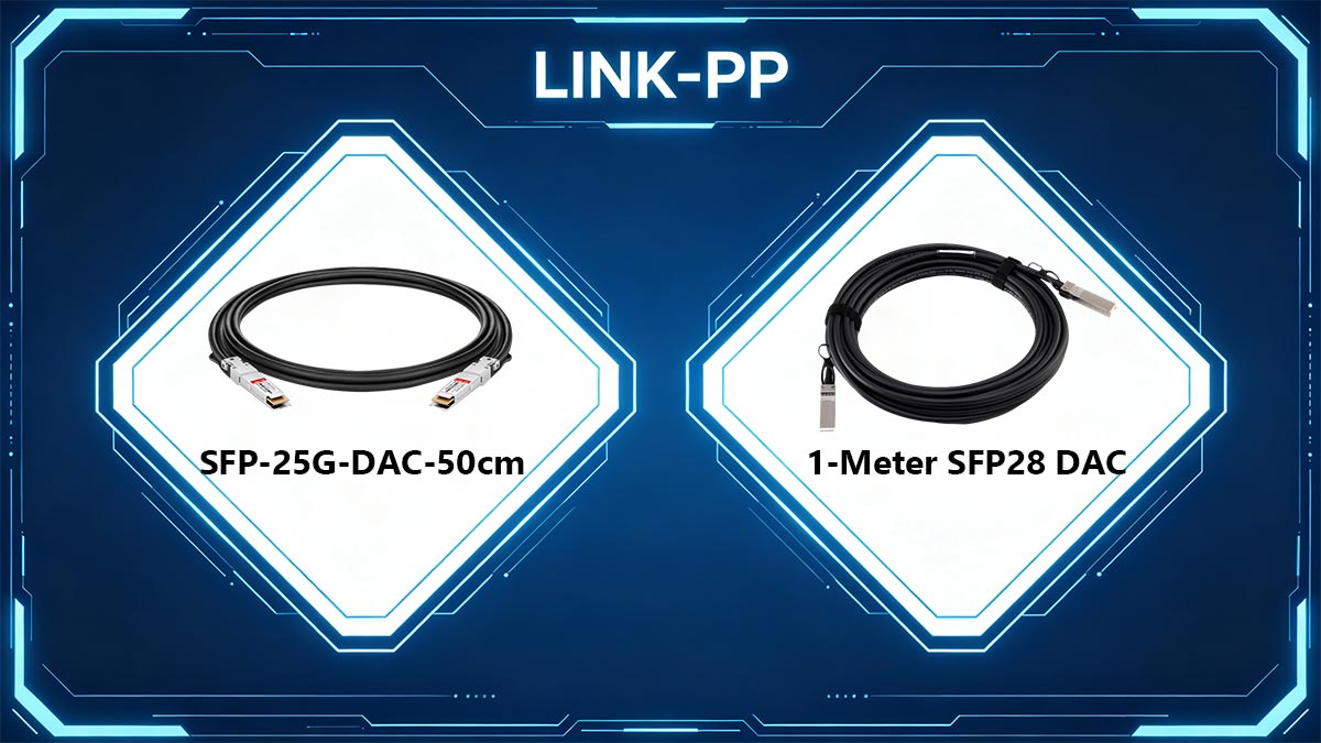
Architecting a 25 Gigabit Ethernet Top-of-Rack (ToR) deployment requires precision at the physical layer. To eliminate ambiguity in your procurement process, apply the following deployment matrix based on your specific infrastructure demands:
Deploy the SFP-25G-DAC-50cm When:
- Latency is the Primary KPI: You are building High-Frequency Trading (HFT) or NVMe-over-Fabrics (NVMe-oF) clusters and require the ability to run a "No-FEC" configuration to shave off ~250 nanoseconds of processing latency per hop.
- Hardware is Vertically Adjacent: Your server's PCIe Network Interface Card (NIC) and the target ToR switch port are located on the same side of the rack and are separated by no more than 1 to 2 Rack Units (U).
- Thermal Budgets are Strict: You want the absolute lowest power draw and minimal cable bulk obstructing the server's exhaust airflow.
Deploy the 1-Meter SFP28 DAC When:
- Navigating Cross-Rack Geometries: The server NIC and switch ports are located on opposite sides of the chassis, requiring diagonal routing that would exceed the strict minimum bend radius of a 50cm twinax cable.
- Utilizing Cable Management Arms (CMA): Your data center standards mandate the use of Velcro service loops and strain relief, which require the physical slack that only a 1m or longer cable can provide.
- Standard RS-FEC is Acceptable: Your application stack is not sensitive to the sub-microsecond latency introduced by standard Reed-Solomon Error Correction.
Whether you prioritize the flawless electrical eye diagram of the 50cm cable or the routing flexibility of the 1-meter variant, the success of your layer-1 infrastructure ultimately depends on build quality and EEPROM compatibility. Implementing strict vendor-coded cables ensures your hardware initializes instantly without triggering unsupported transceiver errors.
To guarantee seamless integration with Tier-1 switches (including Cisco, Mellanox, and Ubiquiti) and access a comprehensive portfolio of MSA-compliant infrastructure, visit the
LINK-PP Official Store for optical transceiver and
DAC cable solutions. Equipping your data center with strictly tested, OEM-compatible interconnects is the most effective strategy to safeguard your 25G network's signal integrity and uptime.










































