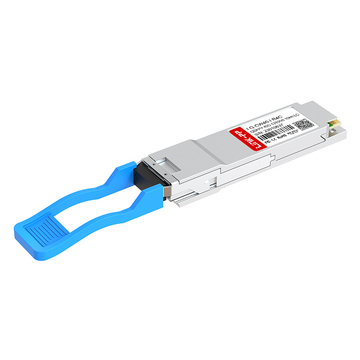
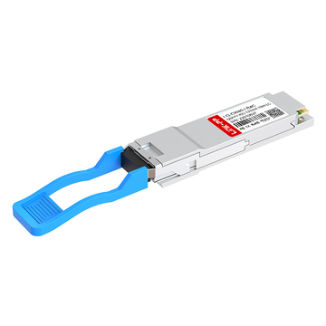
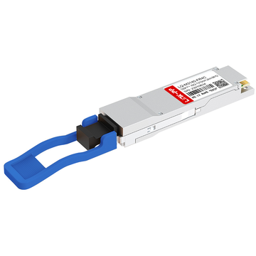
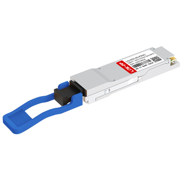
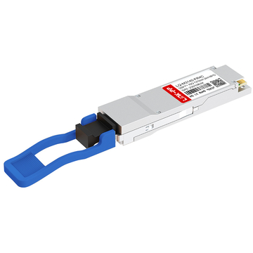
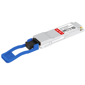
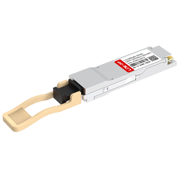
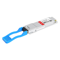
As data centers expand east-west traffic and enterprises transition from 10Gbps to 40Gbps backbones, medium- to long-reach single-mode connectivity becomes a key architectural decision. QSFP 40G PSM4 is widely deployed in these scenarios because it enables 40Gbps transmission over parallel single-mode fiber at distances of 2km and up to 10km, without relying on wavelength multiplexing technologies.
Unlike duplex LC-based long-reach optics such as 40G LR4, QSFP 40G PSM4 uses an MPO interface with 8 fibers to transmit four independent 10Gbps lanes in parallel at 1310nm. This parallel single-mode architecture makes it particularly suitable for spine-leaf data center designs, inter-building campus connectivity, and high-density aggregation layers where extended reach and predictable optical performance are required.
This guide focuses on practical application scenarios and deployment solutions. It explains where QSFP 40G PSM4 fits within modern network topologies, how to design the correct fiber infrastructure, and what technical considerations ensure stable operation and future scalability.
⌛What Is QSFP 40G PSM4?
QSFP 40G PSM4 is a parallel single-mode 40Gbps optical transceiver designed for medium- to long-reach data center and campus interconnections. It transmits four independent 10Gbps lanes over eight single-mode fibers using an MPO connector, typically supporting transmission distances of 2km and in some implementations up to 10km.

Unlike CWDM-based 40G optics that multiplex wavelengths onto duplex fiber, PSM4 relies on parallel transmission at 1310nm, which simplifies optical design while increasing fiber count requirements. This makes it especially suitable for environments where single-mode fiber is readily available and predictable performance over multi-kilometer distances is required.
Core Technical Specifications
QSFP 40G PSM4 modules follow QSFP+ MSA standards and are engineered for parallel optical transmission over OS2 single-mode fiber.
Key technical characteristics are summarized below:
| Parameter | Specification | Notes |
|---|---|---|
| Form Factor | QSFP+ | Hot-pluggable |
| Data Rate | 40Gbps (4×10Gbps) | NRZ signaling |
| Fiber Type | OS2 Single-Mode | Parallel transmission |
| Connector Type | MPO-12 (8 fibers used) | 4 Tx + 4 Rx |
| Reach | 2km / up to 10km | Depends on module version |
Because each lane operates independently, the optical design avoids wavelength multiplexing filters. This reduces internal optical complexity but requires precise MPO fiber alignment and loss control.
How PSM4 Differs from Other 40G Optics
QSFP 40G PSM4 differs from other 40G optical modules primarily in transmission method, fiber usage, and deployment focus.
The architectural differences are summarized below:
| Module Type | Fiber Interface | Typical Reach | Transmission Method |
|---|---|---|---|
| PSM4 | MPO (8 fibers) | 2km / 10km | Parallel SMF |
| LR4 | Duplex LC | 10km | CWDM over SMF |
| SR4 | MPO (MMF) | 100–150m | Parallel MMF |
Key distinctions:
-
PSM4 vs LR4
-
PSM4 uses 8 single-mode fibers; LR4 uses duplex fiber.
-
LR4 relies on wavelength multiplexing; PSM4 uses independent parallel lanes.
-
PSM4 avoids CWDM optics complexity but consumes more fiber resources.
-
-
PSM4 vs SR4
-
PSM4 operates on single-mode fiber; SR4 uses multimode fiber.
-
PSM4 supports multi-kilometer distances; SR4 is designed for short intra-rack or intra-row links.
-
In practical deployments, QSFP 40G PSM4 is often selected when network designers require longer reach than SR4 but prefer a parallel optical architecture instead of wavelength multiplexing used in LR4 systems.
⌛Key Application Scenarios for QSFP 40G PSM4
QSFP 40G PSM4 is primarily deployed in environments that require multi-kilometer single-mode connectivity without the complexity of CWDM optics. It is best suited for spine-leaf interconnections, campus building links, data center interconnect (DCI), and aggregation layers where OS2 fiber infrastructure is available and fiber count is not a limiting factor.

Data Center Spine-Leaf Architecture
QSFP 40G PSM4 is widely used for 40G uplinks between leaf and spine switches in medium- to large-scale data centers where link distances exceed multimode limitations.
In spine-leaf topologies, predictable latency and stable optical power margins are critical. PSM4 enables consistent 40Gbps transmission across rows or halls within the same facility, especially when distances approach or exceed 150m, where SR4 transceiver becomes unsuitable.
Typical design considerations:
-
OS2 single-mode fiber backbone
-
MPO-12 trunk cabling (8 fibers active)
-
Structured patch panel architecture
-
Redundant spine uplinks for high availability
Compared to short-reach multimode solutions, PSM4 provides greater distance flexibility while maintaining high port density in QSFP+ form factor switches.
Large-Scale Data Center Interconnect (DCI)
QSFP 40G PSM4 is suitable for interconnecting separate data center buildings within the same campus over distances of 2km or extended versions up to 10km.
For metro-scale or campus DCI that does not justify DWDM systems, PSM4 offers a simpler optical architecture.
Deployment characteristics:
| Scenario | Distance Range | Fiber Type | Design Benefit |
|---|---|---|---|
| Same-campus DCI | Up to 2km | OS2 SMF | Simple parallel optics |
| Extended campus | Up to 10km | OS2 SMF | No CWDM filters required |
Because PSM4 uses independent lanes instead of multiplexed wavelengths, it reduces sensitivity to wavelength drift and simplifies optical alignment, though it requires careful MPO loss management.
Enterprise Core Network Upgrades
Enterprises upgrading from 10Gbps aggregation layers to 40Gbps backbone links often select QSFP 40G PSM4 when existing single-mode fiber infrastructure is already deployed.
In these scenarios, PSM4 supports:
-
Core switch interconnections across buildings
-
Aggregation-to-core uplinks
-
Gradual migration strategies from multiple 10G links to consolidated 40G trunks
Upgrade logic typically follows:
-
Evaluate existing OS2 fiber availability
-
Confirm MPO trunk feasibility or install parallel trunks
-
Validate link budget for 2km or 10km reach
-
Deploy redundant 40G uplinks for resiliency
This approach avoids re-cabling with duplex LC infrastructure when parallel fiber trunks are already present.
Cloud and Colocation Environments
In multi-tenant cloud or colocation data centers, QSFP 40G PSM4 enables scalable rack-to-aggregation and cross-hall connectivity over single-mode fiber.
These environments often require:
-
High-density 40G switch ports
-
Predictable medium-distance connectivity
-
Standardized MPO cabling systems
Because PSM4 operates entirely over single-mode fiber, it aligns well with data centers standardizing on OS2 cabling for long-term scalability toward higher speeds.
While it consumes more fibers than duplex solutions, the structured MPO infrastructure commonly deployed in hyperscale and colocation facilities offsets this limitation, making QSFP 40G PSM4 a practical option for multi-kilometer 40G connectivity.
⌛Practical Deployment Solutions Using QSFP 40G PSM4
40G QSFP PSM4 is best deployed in structured single-mode environments where parallel MPO infrastructure is planned in advance. The most effective designs focus on spine-leaf uplinks, campus interconnections, and 10G-to-40G aggregation consolidation, while carefully managing fiber count and link loss.

Below are practical solution models that align with real-world network architectures.
Solution 1 – Leaf-to-Spine 40G Uplink Design
For medium to large data centers, QSFP 40G PSM4 provides stable 40Gbps uplinks between leaf and spine switches over OS2 fiber at distances up to 2km or extended 10km versions where required.
Recommended topology characteristics:
-
QSFP+ 40G PSM4 ports on leaf and spine switches
-
MPO-12 trunk cabling (8 fibers active)
-
Structured patch panel for centralized fiber management
-
Dual-uplink redundancy per leaf switch
Because PSM4 uses parallel lanes, end-to-end MPO connectivity must maintain consistent polarity and low insertion loss.
Typical deployment model:
| Component | Recommendation | Purpose |
|---|---|---|
| Fiber Type | OS2 Single-Mode | Multi-kilometer reach |
| Connector | MPO-12 | 8-fiber parallel transmission |
| Topology | Dual-homed leaf | Redundancy and load sharing |
| Distance | 2km / 10km | Campus-scale flexibility |
This design is particularly suitable when multimode SR4 cannot meet distance requirements and LR4 duplex infrastructure is not preferred.
Solution 2 – Campus Interconnection (Building-to-Building)
QSFP 40G PSM4 is commonly deployed to interconnect core switches across buildings within enterprise or university campuses.
This solution avoids CWDM multiplexing systems while still achieving multi-kilometer reach.
Deployment steps:
-
Verify available OS2 single-mode fiber routes between buildings
-
Confirm MPO trunk or deploy new 8-fiber parallel trunks
-
Calculate total channel loss including connectors and patch panels
-
Validate optical budget margin before production deployment
Design comparison for campus interconnect:
| Design Option | Fiber Count | Reach | Complexity |
|---|---|---|---|
| PSM4 | 8 fibers | 2km–10km | Moderate |
| LR4 | 2 fibers | Up to 10km | Higher optical complexity |
PSM4 simplifies optical architecture by eliminating wavelength multiplexing components, making troubleshooting and optical monitoring more straightforward in some environments.
Solution 3 – 10G to 40G Aggregation Strategy
In enterprise networks consolidating multiple 10G uplinks into higher-capacity backbone links, QSFP 40G PSM4 supports efficient traffic aggregation when infrastructure planning allows parallel fiber deployment.
Rather than maintaining four independent 10G SFP+ uplinks, organizations can deploy a single 40G PSM4 trunk between aggregation and core layers.
Typical migration logic:
-
Assess traffic growth across aggregation switches
-
Replace multiple 10G uplinks with a 40G backbone link
-
Implement link aggregation (LACP) at 40G layer if redundancy is required
-
Maintain structured MPO cabling for future scalability
Decision considerations:
-
If OS2 fiber is already available → PSM4 is practical
-
If only duplex LC fiber exists → LR4 transceiver may be simpler
-
If distance <150m → SR4 may be more economical
This solution reduces switch port consumption while increasing bandwidth density, making it suitable for growing enterprise networks or cloud edge facilities.
⌛Cabling Infrastructure Requirements
QSFP 40G PSM4 requires a properly designed parallel single-mode cabling system to achieve stable 2km or 10km transmission. Because it uses 8 active fibers through an MPO interface, fiber type selection, polarity management, and insertion loss control directly determine link reliability and optical margin.
A well-planned MPO-based single-mode infrastructure is essential for predictable performance.

Fiber Type Selection
QSFP 40G PSM4 is designed for OS2 single-mode fiber, which supports long-distance transmission at 1310nm with low attenuation.
OS2 fiber is required to meet multi-kilometer reach targets.
| Parameter | OS2 Single-Mode | Design Impact |
|---|---|---|
| Operating Wavelength | 1310nm | Optimized for PSM4 |
| Typical Attenuation | ~0.4dB/km | Supports 2km–10km reach |
| Core Type | Single-mode | Eliminates modal dispersion |
| Deployment Scope | Campus / DCI | Long-distance backbone |
Because PSM4 operates on independent 10Gbps lanes, consistent attenuation across all eight fibers is critical. Uneven loss between transmit and receive fibers can cause lane imbalance and degrade link stability.
Key planning considerations:
-
Avoid mixing different fiber grades
-
Minimize unnecessary patch panel transitions
-
Maintain consistent splice quality across all lanes
MPO Connector Best Practices
QSFP 40G PSM4 uses an MPO-12 connector with 8 active fibers (4 Tx + 4 Rx). Proper MPO handling is crucial to maintaining acceptable insertion loss across the entire link.
Low insertion loss and correct polarity are mandatory for stable operation.
| Factor | Recommendation | Reason |
|---|---|---|
| Connector Type | MPO-12 | 8 fibers active |
| Polarity | Type B commonly used | Ensures correct Tx/Rx mapping |
| Cleaning Method | Inspection + dry/wet cleaning | Reduces return loss |
| Insertion Loss Target | ≤1.5dB total channel (typical design goal) | Maintains optical margin |
Because parallel optics are sensitive to total channel loss across multiple connectors, each additional MPO connection increases cumulative attenuation. Designers should:
-
Limit patch panel hops
-
Use low-loss MPO trunks
-
Inspect connectors before every insertion
-
Validate polarity before commissioning
Structured Cabling Strategy for Scalability
Parallel single-mode systems require careful planning to ensure long-term scalability.
A modular MPO trunk architecture supports future speed upgrades while protecting fiber investment.
Recommended practices:
-
Deploy MPO trunk cabling between distribution areas
-
Use modular cassette panels for flexibility
-
Reserve dark fibers for future expansion
-
Label all trunks clearly for polarity tracking
Because QSFP 40G PSM4 relies on parallel lanes similar to higher-speed parallel optics, structured MPO infrastructure can support migration paths toward future parallel 100G architectures without complete re-cabling.
⌛QSFP 40G PSM4 vs Other 40G Optical Modules
QSFP 40G PSM4 is positioned between short-reach multimode solutions and wavelength-multiplexed long-reach optics. It is most suitable when multi-kilometer single-mode transmission is required but designers prefer a parallel optical architecture over CWDM-based duplex solutions.
To determine when PSM4 is the appropriate choice, it is necessary to compare it with the two most commonly deployed 40G transceiver: 40GBASE-LR4 and 40GBASE-SR4

PSM4 vs 40GBASE-LR4
Both PSM4 and 40GBASE-LR4 support long-distance transmission over single-mode fiber, but they differ significantly in optical architecture and fiber usage.
PSM4 prioritizes parallel simplicity, while LR4 prioritizes fiber efficiency.
| Feature | QSFP 40G PSM4 | 40GBASE-LR4 |
|---|---|---|
| Fiber Interface | MPO (8 fibers) | Duplex LC (2 fibers) |
| Transmission Method | Parallel 4×10G | CWDM multiplexing |
| Typical Reach | 2km / 10km | 10km |
| Optical Complexity | Lower | Higher (CWDM filters) |
Deployment implications:
-
PSM4 consumes more fiber strands but avoids wavelength multiplexing components.
-
LR4 minimizes fiber count but introduces CWDM optical filters and wavelength alignment requirements.
-
In environments with abundant OS2 fiber trunks, PSM4 can be operationally simpler.
-
Where fiber scarcity is a concern, LR4 may be preferred.
From a troubleshooting perspective, parallel optics can simplify lane-level diagnostics because each lane operates independently without wavelength aggregation.
PSM4 vs 40GBASE-SR4
QSFP 40G PSM4 and 40GBASE-SR4 both use parallel transmission, but they target completely different distance ranges and fiber types.
PSM4 is designed for multi-kilometer single-mode links, while SR4 is optimized for short-reach multimode deployments.
| Feature | QSFP 40G PSM4 | 40GBASE-SR4 |
|---|---|---|
| Fiber Type | OS2 Single-Mode | OM3/OM4 Multimode |
| Connector | MPO | MPO |
| Typical Reach | 2km / 10km | 100–150m |
| Primary Use | Campus / DCI | Intra-DC short links |
Selection logic:
-
If link distance exceeds 150m → SR4 is insufficient.
-
If single-mode backbone is standardized → PSM4 aligns better.
-
If distance is within a rack or row → SR4 is typically more economical.
While both modules use MPO connectivity, the difference in fiber type and optical reach defines their deployment boundaries.
Summary of Deployment Positioning
Each 40G optical module serves a distinct infrastructure model:
-
PSM4 → Parallel single-mode, medium-to-long reach (2km–10km), fiber-rich environments
-
LR4 → Duplex single-mode, long reach (10km), fiber-limited scenarios
-
SR4 → Parallel multimode, short reach (<150m), intra-data center links
QSFP 40G PSM4 becomes the preferred option when multi-kilometer transmission is required and the network design favors structured MPO single-mode cabling without introducing wavelength multiplexing complexity.
⌛Advantages and Limitations of QSFP 40G PSM4
QSFP 40G PSM4 is designed for parallel single-mode transmission over multi-kilometer distances, making it suitable for campus, DCI, and backbone aggregation environments. However, its fiber requirements and infrastructure dependencies define clear deployment boundaries.

Understanding both strengths and constraints ensures correct architectural decisions.
Advantages
QSFP 40G PSM4 provides a balance between distance capability and architectural simplicity when parallel single-mode infrastructure is available.
Key advantages include:
-
Multi-kilometer reach (2km / 10km)
Supports campus and building-to-building connectivity beyond multimode limits. -
Parallel optical architecture
Uses independent 10Gbps lanes, avoiding CWDM filters and wavelength management. -
Compatibility with structured MPO systems
Aligns with data centers standardized on MPO trunk cabling. -
Lane-level performance visibility
Independent channels simplify optical diagnostics and monitoring. -
Predictable performance at 1310nm
Optimized for OS2 single-mode fiber with stable attenuation characteristics.
Performance positioning overview:
| Aspect | Benefit | Deployment Impact |
|---|---|---|
| Reach | 2km–10km | Suitable for campus / DCI |
| Architecture | Parallel SMF | No wavelength multiplexing |
| Fiber Type | OS2 | Long-term scalability |
| Diagnostics | Independent lanes | Simplified troubleshooting |
These characteristics make PSM4 particularly effective in fiber-rich environments where structured parallel cabling is already in place.
Limitations
Despite its advantages, QSFP 40G PSM4 is not universally optimal. Its design introduces specific trade-offs that must be considered during network planning.
Primary limitations include:
-
High fiber consumption
Requires 8 active fibers per link (MPO-12 interface). -
MPO dependency
Deployment demands correct polarity management and strict connector hygiene. -
Not optimized for short links
For distances under 150m, multimode SR4 is typically more cost-efficient. -
Less fiber-efficient than duplex solutions
Compared to CWDM-based long-reach modules, fiber usage is higher.
Constraint summary:
| Factor | Limitation | Design Consideration |
|---|---|---|
| Fiber Count | 8 fibers per link | Ensure trunk capacity |
| Connector Type | MPO required | Polarity planning |
| Short-Distance Use | Not cost-optimal | Consider SR4 instead |
| Fiber Efficiency | Lower than duplex LR4 | Evaluate fiber availability |
In environments where fiber strands are limited or only duplex LC infrastructure exists, alternative 40G modules may be more practical.
⌛Design Considerations Before Deployment
Before deploying QSFP 40G PSM4, network designers must validate link budget, fiber infrastructure readiness, and equipment compatibility. Because the module relies on parallel single-mode transmission over 8 fibers, improper loss calculation or polarity mismatch can directly affect link stability across 2km or 10km distances.
Careful pre-deployment validation minimizes operational risk.

Link Budget and Loss Calculation
QSFP 40G PSM4 must operate within its defined optical budget to ensure all four lanes maintain stable signal integrity. Total channel attenuation includes fiber loss, connector loss, splice loss, and engineering margin.
Total channel loss must remain below the module's specified receive sensitivity threshold.
| Loss Component | Typical Value | Planning Impact |
|---|---|---|
| OS2 Fiber | ~0.4dB/km | Distance-dependent |
| MPO Connector (per pair) | 0.35–0.5dB | Accumulates per hop |
| Splice Loss | 0.1–0.2dB | Depends on quality |
| Safety Margin | ≥1dB | Stability buffer |
Pre-deployment calculation steps:
-
Measure total fiber distance (km).
-
Multiply by attenuation coefficient (~0.4dB/km at 1310nm).
-
Add connector and patch panel loss.
-
Include splice loss if applicable.
-
Reserve ≥1dB safety margin.
For extended 10km versions, fiber attenuation alone may approach ~4dB, making connector minimization especially important.
Uneven loss across lanes should also be avoided, as parallel optics require balanced performance across all transmit and receive fibers.
Compatibility and Interoperability
QSFP 40G PSM4 modules follow QSFP+ MSA guidelines, but compatibility validation is still required before production deployment.
Switch compatibility and firmware validation are mandatory.
Key checks include:
-
Confirm switch vendor support for 40G PSM4 optics
-
Validate firmware recognition of DOM (Digital Optical Monitoring) parameters
-
Verify that port configuration supports 40G native mode
-
Test interoperability in mixed-vendor environments if applicable
Because PSM4 uses parallel lanes, lane-level diagnostics should be reviewed during testing to confirm uniform optical power readings across all four channels.
MPO Polarity and Physical Layer Validation
Parallel transmission requires strict polarity control. Incorrect MPO polarity will result in Tx/Rx misalignment and link failure.
Polarity must be validated before live deployment.
Common design considerations:
-
Confirm trunk polarity type (Type A / B / C)
-
Ensure transmit fibers align with receive fibers
-
Avoid mixing trunk polarity standards
-
Perform end-to-end light source testing before switch installation
Improper polarity is one of the most frequent causes of link-down scenarios in parallel optical deployments.
Pre-Deployment Validation Checklist
Before commissioning QSFP 40G PSM4 links:
-
✓ Confirm OS2 single-mode fiber continuity
-
✓ Validate MPO connector cleanliness
-
✓ Calculate total channel loss
-
✓ Verify polarity alignment
-
✓ Test module recognition and DOM readings
-
✓ Confirm redundancy configuration
Completing these steps ensures stable 40Gbps parallel single-mode transmission across multi-kilometer campus or data center links.
⌛Future Scalability and Migration Path
QSFP 40G PSM4 deployments should be evaluated not only for current bandwidth requirements but also for future upgrade potential. Because it relies on structured MPO-based single-mode infrastructure, its long-term value depends largely on how well the cabling system supports higher-speed parallel optics.
A properly designed PSM4 infrastructure can reduce re-cabling costs during future migrations.

Preparing for 100G Upgrades
Networks deploying 40G PSM4 today often anticipate migration to 100G or higher speeds. The feasibility of that transition depends on fiber count, trunk architecture, and connector standardization.
Parallel single-mode trunk infrastructure can support higher-speed migration if planned correctly.
| Current Deployment | Future Option | Fiber Impact | Migration Complexity |
|---|---|---|---|
| 40G PSM4 (8 fibers) | 100G parallel optics | May require additional fibers | Moderate |
| 40G PSM4 trunk system | Higher-density MPO trunks | Reusable backbone | Low |
| OS2 single-mode | 100G/400G SMF optics | No fiber type change | Low |
Key considerations:
-
100G parallel solutions may require 8 or more active fibers depending on architecture.
-
If existing trunks use MPO-12 or MPO-24, expansion may be straightforward.
-
Maintaining standardized polarity simplifies future module replacement.
If OS2 single-mode fiber is already deployed for PSM4, no change in fiber type is required for most higher-speed single-mode solutions.
Investment Protection Through Structured MPO Design
The scalability of QSFP 40G PSM4 largely depends on whether the cabling was deployed as a structured system rather than point-to-point patching.
Structured trunk-based MPO architecture protects long-term investment.
Recommended strategy:
-
Deploy centralized distribution areas with modular MPO trunks
-
Reserve additional dark fibers for expansion
-
Use high-fiber-count trunks (e.g., MPO-24) when possible
-
Standardize labeling and polarity documentation
This approach reduces the need for major physical infrastructure changes during bandwidth upgrades.
Transition Strategy: From 40G to Higher-Speed Architectures
When traffic growth exceeds 40Gbps link capacity, organizations typically consider:
-
Replacing 40G links with 100G native ports
-
Increasing link aggregation at 40G temporarily
-
Redesigning spine-leaf topology for higher port density
The appropriate path depends on:
-
Available switch hardware capabilities
-
Existing fiber strand availability
-
Rack density and oversubscription ratio
If the underlying single-mode MPO backbone was designed with expansion in mind, the transition can often occur at the transceiver and switch level without replacing the entire cabling infrastructure.
⌛FAQs About QSFP 40G PSM4

Q1: Is QSFP 40G PSM4 hot-swappable?
Yes. QSFP 40G PSM4 follows the QSFP+ MSA standard and supports hot-plug operation, allowing insertion or removal without powering down the switch (if the platform supports hot-swap).
Q2: Does QSFP 40G PSM4 support Digital Optical Monitoring (DOM)?
Most compliant modules support DOM, enabling real-time monitoring of transmit power, receive power, temperature, and voltage through the switch interface.
Q3: Can QSFP 40G PSM4 interoperate between different switch vendors?
Interoperability is generally possible if both sides comply with QSFP+ MSA and IEEE standards. However, vendor compatibility validation is recommended before deployment, especially in mixed-brand environments.
Q4: What wavelength does QSFP 40G PSM4 operate at?
QSFP 40G PSM4 typically operates around 1310nm, using parallel single-mode transmission across four independent optical lanes.
Q5: Is breakout (4×10G) supported with QSFP 40G PSM4?
No. QSFP 40G PSM4 is not designed for 4×SFP+ breakout. Breakout functionality depends on switch capability and module type; PSM4 modules are generally used as native 40G links.
Q6: What testing method is recommended before commissioning?
An end-to-end light source and power meter test is recommended to verify total channel loss and polarity alignment before installing active equipment.
Q7: In which environments is QSFP 40G PSM4 most commonly deployed?
It is commonly deployed in campus backbones, inter-building connections, aggregation layers, and data center interconnect scenarios where structured single-mode MPO infrastructure is available.
⌛Conclusion

QSFP 40G PSM4 provides a practical solution for multi-kilometer 40Gbps connectivity over parallel single-mode fiber. It bridges the gap between short-reach multimode optics and wavelength-multiplexed long-reach modules, making it well suited for campus backbones, building-to-building interconnects, aggregation layers, and structured MPO-based data center environments.
Its value lies in combining 2km to 10km reach with a parallel optical architecture that avoids CWDM complexity while leveraging standardized OS2 infrastructure. When link budget planning, MPO polarity management, and compatibility validation are handled correctly, QSFP 40G PSM4 delivers stable and scalable 40G performance.
If you are planning a 40G backbone deployment or upgrading your campus network, explore compatible QSFP 40G PSM4 modules and related MPO cabling solutions at LINK-PP Official Store to ensure reliable performance and long-term infrastructure scalability.