As 100G Ethernet becomes the baseline speed for modern data centers and enterprise backbones, network engineers often face a practical question: how to deliver 100G capacity over single-mode fiber without resorting to overly expensive long-haul optics?
This is exactly where QSFP 100G LR4 stands out. Designed for long-reach 100G links on 1310nm single-mode fiber (SMF), QSFP 100G LR4 has become a go-to choice for connecting switches, routers, and interconnect systems across buildings, campuses, and metro-edge facilities — while still keeping the deployment simple and standardized.
? What is QSFP 100G LR4 Optical Module
As one of the most popular transceiver types in 100G Ethernet applications, the QSFP 100G LR4 offers a powerful combination of long reach, compact form factor, and compatibility with single-mode fiber networks. To better understand why it has become an industry standard, let’s break down its definition, wavelength choice, and functional importance in 100G networks.
Definition of QSFP 100G LR4
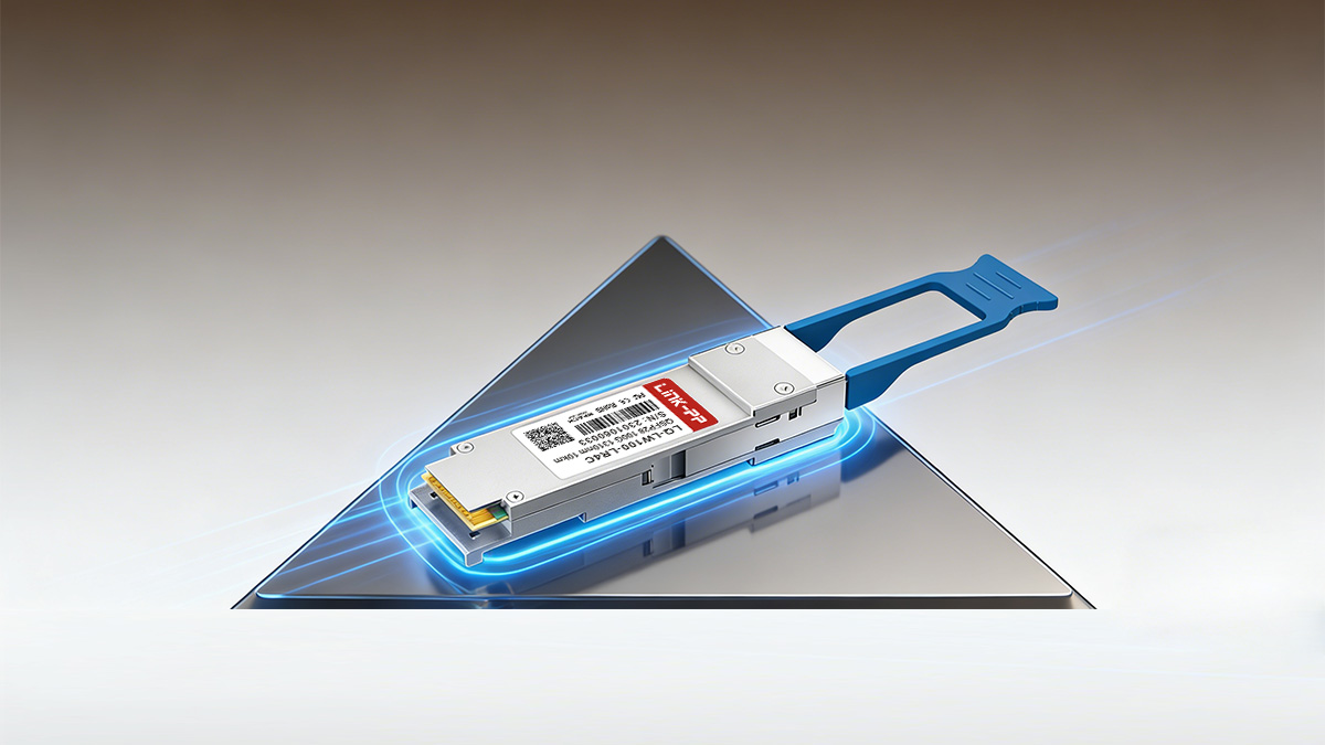
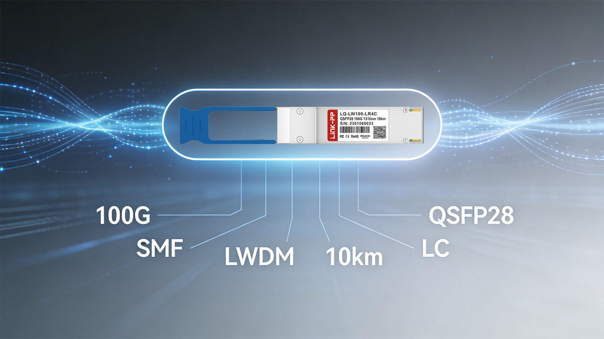
QSFP 100G LR4 (often written as QSFP28 100GBASE LR4) is a 100-Gigabit Ethernet optical transceiver module that supports up to 10km transmission distance over single-mode fiber (OS2). The “QSFP” refers to the compact pluggable form factor (Quad Small Form-factor Pluggable), while “LR” means Long Reach, and “4” indicates that the optical signal is carried using four separate optical lanes (four wavelengths).
Instead of sending one 100G optical stream on a single wavelength, QSFP 100GBASE LR4 splits the data into four 25G channels, converts them into four different wavelengths in the 1310nm region, and transmits them together over a pair of single-mode fibers (one for transmit, one for receive). On the receiving end, the wavelengths are separated and recombined back into a 100G data stream.
Why 1310nm is Used for Long-Reach Transmission
The 1310nm window is widely used for long-reach single-mode transmission because it offers a strong balance of low attenuation, stable performance, and manageable dispersion for typical Ethernet distances. Compared with 850nm (commonly used for multimode short reach), 1310nm performs far better on single-mode fiber, enabling multi-kilometer connectivity without excessive optical loss.
Another key reason is practicality: the 1310nm region supports CWDM (Coarse Wavelength Division Multiplexing) spacing well, allowing LR4 modules to place four wavelengths close to each other without requiring the tighter spacing and higher cost typically associated with DWDM systems. This CWDM-friendly characteristic is central to LR4’s design philosophy — extend reach while staying cost-effective and deployment-efficient for mainstream 100G Ethernet networks.
Role of QSFP 100GBASE LR4 in 100G Ethernet Networks
In a 100G Ethernet architecture, QSFP 100G LR4 often serves as the default single-mode “workhorse” optic for longer links where SR4 can’t reach, and ER4 may be unnecessary or too costly. You’ll typically see LR4 used to connect:
- Leaf-to-spine switch uplinks across rows or halls
- Data center interconnect (DCI) links between nearby facilities
- Enterprise core/backbone upgrades where SMF already exists
- Campus or metro-edge aggregation requiring consistent 100G reach
Operationally, LR4 helps standardize 100G deployments because it fits into the QSFP28 high-density ecosystem and aligns with a widely recognized Ethernet specification (100GBASE-LR4). That means easier planning around distance budgets, predictable interoperability expectations (when compatibility requirements are followed), and a straightforward upgrade path from legacy SMF infrastructures to 100G — without needing to redesign the fiber plant.
? How QSFP 100G LR4 Works in 1310nm Single-Mode Fiber Transmission
At a high level, QSFP 100G LR4 achieves 100G transmission by splitting a 100G signal into four parallel lanes, converting them into four optical wavelengths, and sending them together over single-mode fiber. This design combines the compact QSFP28 form factor with CWDM optics so you can reach 10km distances without needing complex long-haul transport gear.
4×25G Electrical Lanes inside QSFP28 LR4
Inside a QSFP28 100G LR4 module, the host device (switch/router/NIC) typically provides a 100G electrical interface that is organized as four high-speed electrical lanes. Each lane carries 25G worth of data, commonly described as 4×25G.
These electrical lanes enter the module through the QSFP28 connector and are handled by internal high-speed electronics. Depending on the module design, functions such as signal conditioning (for example, equalization), lane alignment, and clock/data recovery may be used to maintain clean signaling at 25G per lane. The key idea is simple: the module doesn’t treat 100G as one giant stream — it treats it as four synchronized 25G streams that can be processed and transported efficiently.
CWDM Technology inside QSFP LR4 100G
Once the module has four 25G electrical lanes, it needs a way to transmit them optically over just one pair of fibers (duplex SMF). That’s where CWDM (Coarse Wavelength Division Multiplexing) comes in.
CWDM allows multiple optical signals — each on a different wavelength — to be carried simultaneously on the same fiber. In QSFP 100G LR4, each 25G lane is converted by its own optical transmitter path, and then all four optical lanes are combined into a single output. Because CWDM spacing is relatively wide compared to DWDM, LR4 can keep the optical design practical and cost-effective while still achieving long-reach performance on single-mode fiber.
Four Wavelengths around 1310nm
QSFP 100G LR4 operates in the 1310nm region, but it doesn’t use just one wavelength. It uses four distinct wavelengths “around” 1310nm — each wavelength carrying one 25G lane.
In practice, these wavelengths sit within the 1310nm window and are spaced according to CWDM channel planning (commonly referenced as LAN WDM wavelengths in many LR4 implementations). The benefit of using four nearby wavelengths is that the module can deliver high aggregate bandwidth (100G) while still leveraging the favorable transmission characteristics of single-mode fiber in the 1310nm band.
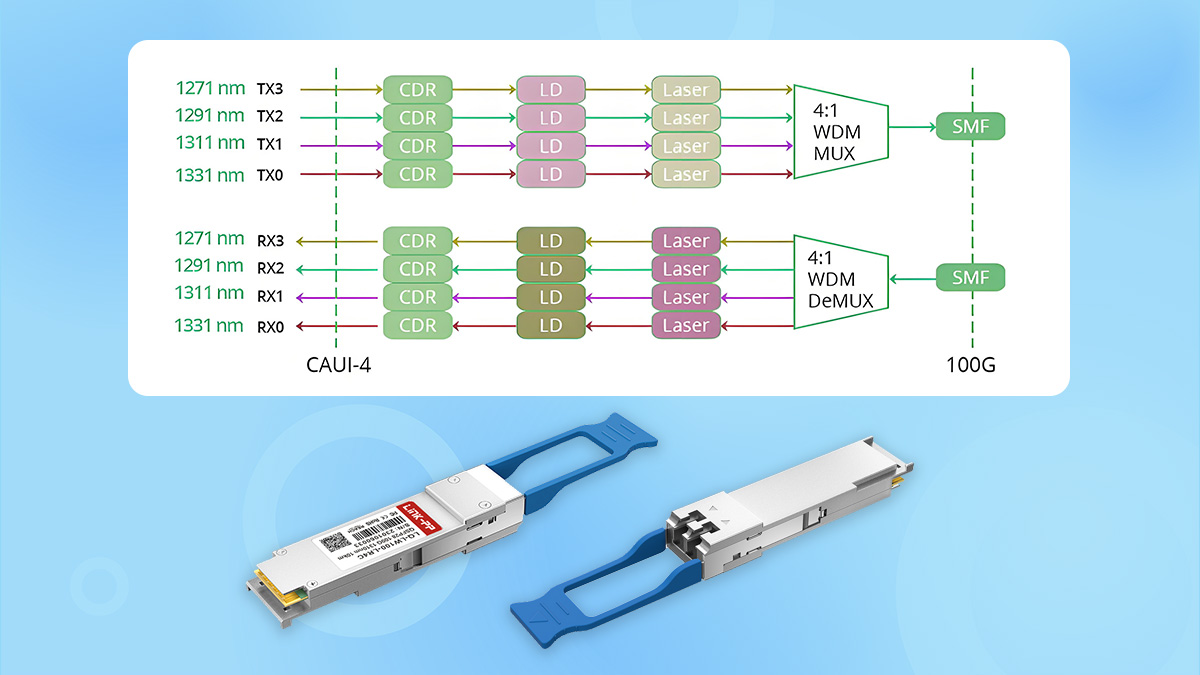
Multiplexing and Demultiplexing Process
The real “magic” of 100GBASE LR4 happens in two opposite processes: multiplexing (MUX) on transmit and demultiplexing (DEMUX) on receive.
On the transmit side (MUX):
1️⃣ The module receives four 25G electrical lanes from the host.
2️⃣ Each lane drives an optical transmitter that generates light at a specific wavelength.
3️⃣ A CWDM MUX optic combines the four wavelengths into one composite optical signal.
4️⃣ That combined signal exits the module through the transmit fiber of the LC duplex interface.
On the receive side (DEMUX):
1️⃣ A composite optical signal arrives on the receive fiber.
2️⃣ A DEMUX optic separates the incoming light into four individual wavelengths.
3️⃣ Each wavelength is detected by its receiver path and converted back to a 25G electrical lane.
4️⃣ The module outputs four 25G lanes back to the host, where they are reassembled into the 100G data stream.
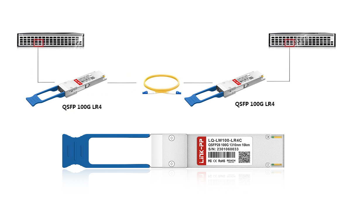
This MUX/DEMUX approach is why QSFP 100G LR4 can keep cabling simple — only one fiber pair is needed — even though internally it’s transporting four parallel channels.
Signal Transmission over Single-mode Fiber
After multiplexing, the combined optical signal travels over single-mode fiber (typically OS2). Single-mode fiber is ideal for long-reach applications because its small core supports a single propagation mode, which helps reduce modal dispersion issues seen in multimode systems.
Over distance, the signal is influenced by link budget factors such as fiber attenuation, connector/splice loss, and receiver sensitivity. With proper optics and clean fiber connectivity, QSFP 100G LR4 is engineered to maintain reliable performance up to 10km, making it well-suited for inter-building links, campus backbones, and larger data center fabrics where multimode optics can’t reach.
? QSFP 100G LR4 vs Other 100G QSFP28 Transceiver
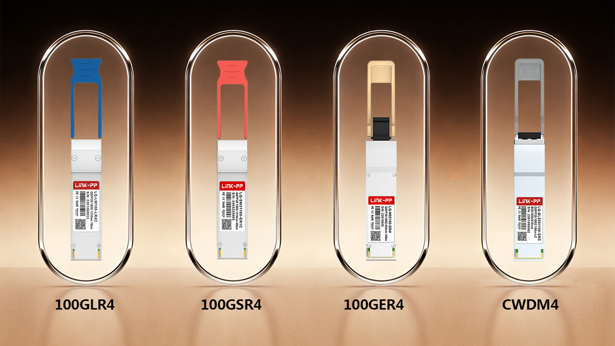
When deploying 100G Ethernet, network engineers often need to choose between several QSFP28 module types, each optimized for different distances and fiber types. QSFP 100G LR4 distinguishes itself by providing a balanced long-reach solution over single-mode fiber, while other 100G modules such as SR4, ER4, and CWDM4 target shorter or longer distances, or slightly different wavelength strategies.
To better illustrate the differences between these 100G QSFP28 transceiver modules, here is a summary table highlighting the main distinctions:
| Module Type |
Fiber Type |
Maximum Distance |
Wavelength |
Connector Type |
Transmission Method |
| QSFP 100G LR4 |
SMF |
Up to 10km |
1295nm, 1300nm, 1304nm, 1309nm |
LC duplex |
CWDM, 4×25G lanes |
| QSFP 100G SR4 |
MMF |
70 - 150m |
850nm |
MTP/MPO |
Parallel, 4×25G lanes |
| QSFP 100G ER4 |
SMF |
Up to 40km |
1295nm, 1300nm, 1304nm, 1309nm |
LC duplex |
CWDM, 4×25G lanes |
| QSFP 100G CWDM4 |
SMF |
Up to 2km |
1271nm, 1291nm, 1311nm, 1331nm |
LC duplex |
CWDM, 4×25G lanes |
QSFP 100G LR4 vs QSFP 100G SR4
QSFP 100G LR4 is designed for long‑reach single‑mode fiber up to about 10km, while QSFP 100G SR4 targets short‑reach multi‑mode fiber deployments typically within 70m on OM3, 100m on OM4, and 150m on OM5. LR4 uses LC duplex connectors over SMF, which simplifies cabling for longer interconnects, whereas SR4 uses an MTP/MPO interface with parallel fibers, making it ideal for high‑density, short intra‑data‑center connections. In practice, LR4 is preferred for spine‑to‑spine or building‑to‑building links, whereas SR4 is more cost‑effective for top‑of‑rack to aggregation switches in the same facility.
QSFP 100G LR4 vs QSFP 100G ER4
Both QSFP 100G LR4 and ER4 operate over single‑mode fiber in the 1310nm region using four wavelengths, but they are optimized for different distances. LR4 typically supports up to 10km, making it well-suited for campus cores and data center interconnect within a metro campus, whereas 100GBASE ER4 extends that reach up to 40km, enabling longer metro or inter‑site connectivity without additional amplifiers. Because ER4 requires more powerful optics and tighter link budgets, it usually comes at a higher cost and may demand more careful optical power management than LR4.
QSFP 100G LR4 vs QSFP 100G CWDM4
QSFP 100G CWDM4 also uses four wavelengths around 1310nm over single‑mode fiber, but it is specified for shorter distances, commonly up to 2km with FEC, which fills the gap between SR4 and LR4 in terms of reach. CWDM4 modules are often more cost‑efficient than LR4 and are widely used inside and between data halls where runs exceed SR4’s multi‑mode limits but do not justify 10km‑class optics. In contrast, LR4 is chosen when network designers need more headroom for future expansion or must cover larger campus, building‑to‑building, or metro‑edge distances on the same pair of single‑mode fibers.
? Typical Use Cases of QSFP 100G LR4 in Network Infrastructure
QSFP 100G LR4 is primarily deployed wherever reliable 100G bandwidth is required over single‑mode fiber at distances beyond the limits of multimode solutions like 100GBASE SR4. It bridges the gap between short‑reach data center connections and more expensive long‑haul optics, making it a practical choice for many core, aggregation, and inter‑site links.
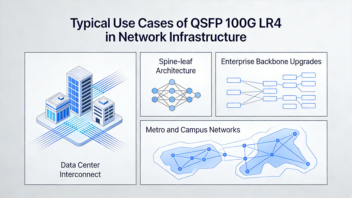
Data Center Interconnect (DCI)
One of the most common scenarios for QSFP28 LR4 is data center interconnect between two facilities that are close enough to stay within the 10km optical budget. This includes linking an enterprise data center to a secondary site, connecting two buildings in the same industrial park, or bridging a primary data hall to an edge computing location. LR4 is especially attractive here because it uses LC duplex over single-mode fiber, which aligns with how many DCI fiber plants are already built (patch panels, ODFs, and structured SMF cabling).
Spine-leaf Architecture
In modern leaf-spine data center fabrics, uplinks from leaf switches to spine switches often need to travel across rows, halls, or separate pods, and those distances can quickly exceed what multimode modules are comfortable with — especially as data centers scale. QSFP 100G LR4 is a strong fit for leaf-spine because it enables high-density 100G uplinks over SMF without requiring MPO-based parallel fiber cabling. That matters operationally: duplex LC patching is simpler to manage, easier to troubleshoot, and often more compatible with existing fiber infrastructure.
Enterprise Backbone Upgrades
Enterprises upgrading campus cores and backbone links from 10G/40G to 100G frequently choose LR4 because it aligns with a common reality: many organizations already have single-mode fiber installed between buildings or campuses.
In this upgrade model, 100G LR4 helps reduce redesign work. Instead of re-cabling for parallel optics or installing additional intermediate switches just to stay within short-reach limits, LR4 can reuse the existing SMF runs and deliver 100G capacity for core routing, aggregation, and high-traffic services (data center access, server farms, storage networks, and internet edge).
Metro and Campus Networks
In metro and large campus networks, QSFP 100G LR4 is commonly used for building‑to‑building, campus‑to‑campus, and aggregation‑to‑core links where distances range from a few hundred meters to several kilometers.
Its 10km reach is well suited for universities, hospitals, industrial parks, and municipal networks that need 100G capacity but do not require 40km optics like QSFP ER4. Service providers and large organizations often deploy LR4 at metro access and aggregation layers to deliver high‑speed services and backhaul traffic efficiently over existing single‑mode fiber infrastructure.
? How to Choose the Right QSFP 100G LR4 Transceiver Module
Choosing the right QSFP 100G LR4 module requires evaluating its technical compatibility, verifying equipment support, and reviewing key optical and performance parameters. The following focuses on how to ensure the transceiver you select aligns perfectly with your network infrastructure.
Compatibility Factors When Selecting a 100GBASE LR4 QSFP Transceiver
When you evaluate a QSFP 100GBASE-LR4 module, prioritize compatibility at three layers: hardware, firmware/software, and optical infrastructure.
? Form Factor and Standard Alignment
- Confirm it is QSFP28 and supports 100GBASE-LR4 (not CWDM4, ER4, or SR4).
- Check it uses duplex LC and is intended for single-mode fiber (OS2).
? Vendor Coding / Interoperability Expectations
- Many switches enforce vendor checks; ensure the module is coded for your platform (or confirmed to be compatible).
- If you use third-party optics, confirm the vendor provides model-specific encoding for your switch OS and hardware revision.
? FEC and Port Configuration
- Some platforms require RS-FEC (or specific FEC settings) to meet error-rate targets at 100G.
- Make sure your port is configured for 100G operation and the correct breakout mode is not accidentally enabled.
? Fiber Plant Fit
- LR4 is designed for SMF reach, but real links include patch panels and splices.
- If your links are very short (e.g., same rack), check whether your platform recommends attenuators or has a minimum receive power guidance (to avoid receiver overload in extreme short links).
How to Verify Switch and Router Support for QSFP LR4 100G
Before purchasing at scale, verify support from both documentation and real-device checks.
? Check the Official Compatibility Matrix
- Look up the exact switch/router model and confirm QSFP28 100GBASE LR4 is listed as supported.
- Validate any constraints such as supported optics per port group, line card, or OS version.
? Confirm Software/Firmware Requirements
- Some platforms only support certain optics after a minimum NOS/firmware release.
- Ensure your target code version matches the requirement for LR4 operation and DOM reporting.
? Validate Port and Feature Readiness
- Confirm the port supports 100G QSFP28 (not only 40G QSFP+).
- Check support for DOM/DDM monitoring, alarms, and optical power thresholds — especially important for troubleshooting.
? Do a Pilot Validation
- Test a pair of modules on representative hardware with your real network scenario.
- Verify link comes up cleanly, no excessive CRC/FEC corrections, and DOM readings look stable after warm-up.
Key Performance Specifications to Check for 100G LR4 QSFP28
Even within “QSFP 100G LR4,” different vendors and module builds can vary. These are the specs that most directly impact link success.
? Reach and Standards
- Rated distance: typically up to 10km on OS2 SMF (confirm the stated reach and assumptions).
- Compliance: look for references to 100GBASE-LR4 and relevant MSA/IEEE compliance statements.
? Optical Budget and Sensitivity
- Confirm the transmit power range, receiver sensitivity, and the stated optical link budget.
- Make sure your calculated losses (fiber + connectors + splices + patch panels) fit comfortably within budget with margin.
? Wavelength Plan
- LR4 uses four wavelengths around 1310nm; ensure it is true 100G LR4 and not 100G CWDM4 if you need full 10km reach.
- Consistent wavelength implementation helps interoperability and predictable performance.
? Power Consumption and Thermal Limits
- Check module max power draw against your platform’s per-port power limit.
- Verify operating temperature range (commercial vs industrial) if your environment has hot aisles, edge cabinets, or limited airflow.
? DOM/DDM Support and Diagnostics
- Prefer modules with full digital diagnostics: Tx/Rx optical power, temperature, supply voltage, and laser bias current.
- Strong diagnostics reduce MTTR when you’re troubleshooting marginal links or dirty connectors.
? QSFP 100G LR4 Installation and Deployment Tips
Proper installation and deployment are critical to ensuring that QSFP 100G LR4 transceivers operate reliably over single-mode fiber. Following best practices minimizes optical loss, prevents damage to the transceiver or cabling, and helps maintain consistent 100G performance across the network.
Proper Fiber Cabling Practices
When connecting 100G LR4 modules, always use high-quality single-mode fiber (SMF) with standard duplex LC connectors. Keep cable runs within the maximum transmission distance, and avoid tight bends or excessive tension that can damage the fiber. Clearly label both ends to ensure accurate connections between transceivers.
Cleaning LC Connectors
Even a small dust particle on LC connectors can cause insertion loss and degrade signal quality. Before plugging in the fiber, clean each connector using lint-free wipes and isopropyl alcohol or a specialized fiber cleaning tool. Regular maintenance of connectors ensures consistent optical performance.
Monitoring Optical Power
Use an optical power meter to verify that the transmitted and received power levels fall within the module’s recommended range. Abnormal readings may indicate fiber damage, connector contamination, or misaligned connections. Continuous monitoring helps detect potential issues before they impact network traffic.
Avoiding Common Deployment Issues
Common problems such as incorrect polarity, mismatch of connector types, or use of multimode fiber can cause link failures. Ensure proper transceiver seating in network equipment and confirm that firmware versions support the QSFP 100G LR4. Following manufacturer guidelines and using compatible components significantly reduces the risk of deployment errors.
? QSFP 100G LR4: Common Questions Answered
What distance does QSFP 100G LR4 support?
QSFP 100G LR4 transceiver modules typically support transmission distances of up to 10km over single-mode fiber. This makes them ideal for long-reach applications such as interconnecting data centers or connecting core network nodes.
How is QSFP 100G LR4 different from QSFP 100G PSM4 modules?
100G LR4 uses four wavelengths around 1310nm with CWDM multiplexing over duplex single-mode fiber, while QSFP 100G PSM4 transmits four 25G lanes over parallel single-mode fibers (usually MPO/MTP). LR4 is better suited for long-reach duplex links, whereas PSM4 is optimized for short, multi-fiber connections.
Is QSFP 100G LR4 backward compatible with 40G or 10G transceivers?
No, QSFP 100G LR4 is not backward compatible with 40G or 10G modules because the optical channels and signaling standards differ. Devices must have 100G-capable ports to interface with LR4 transceivers.
What factors affect QSFP 100G LR4 performance and signal stability?
Performance is influenced by fiber quality, connector cleanliness, optical power levels, and proper temperature management. Maintaining structured cabling and monitoring DOM readings helps ensure stable operation.
Is QSFP 100G LR4 suitable for short-distance connections?
While 100G LR4 can operate over short distances, it’s not the most cost-effective choice for them. For short-reach applications under 150m, 100G SR4 solutions usually offer a better balance of performance and cost.
? Conclusion: Choosing QSFP 100G LR4 for Reliable Single-Mode Fiber Connectivity
QSFP 100G LR4 offers a reliable and standardized solution for delivering 100G Ethernet over single-mode fiber, balancing reach, performance, and ease of deployment. Its CWDM-based 1310nm design, duplex LC interface, and compatibility with modern QSFP28 switches make it ideal for data center interconnects, campus backbones, and metro networks.
For teams planning new 100G deployments or upgrades, selecting the right LR4 modules and following proper installation practices ensures long-term network stability and scalability. To explore certified and cost-effective options, visit the LINK-PP Official Store for a wide selection of QSFP 100G optical transceivers and professional network connectivity solutions.