
As Gigabit Ethernet continues to serve as a foundational technology in enterprise and campus networks, understanding the capabilities of different optical standards is essential for efficient design. Among these, 1000BASE-SX/LX are widely used for short- and long-distance fiber links, offering flexible deployment options ranging from 550m to 10km. Choosing between them is not just about distance — it also involves factors such as wavelength, fiber type, and overall cost.
A critical aspect of deploying 1000BASE-SX/LX links is link budgeting, which determines whether a connection can reliably operate over a given distance. By evaluating transmit power, receiver sensitivity, and total link loss, network engineers can ensure stable performance and avoid signal degradation. This guide examines the primary distinctions between SX and LX, and provides guidance on calculating and optimizing link budgets for practical applications.
? What Is 1000BASE-SX/LX
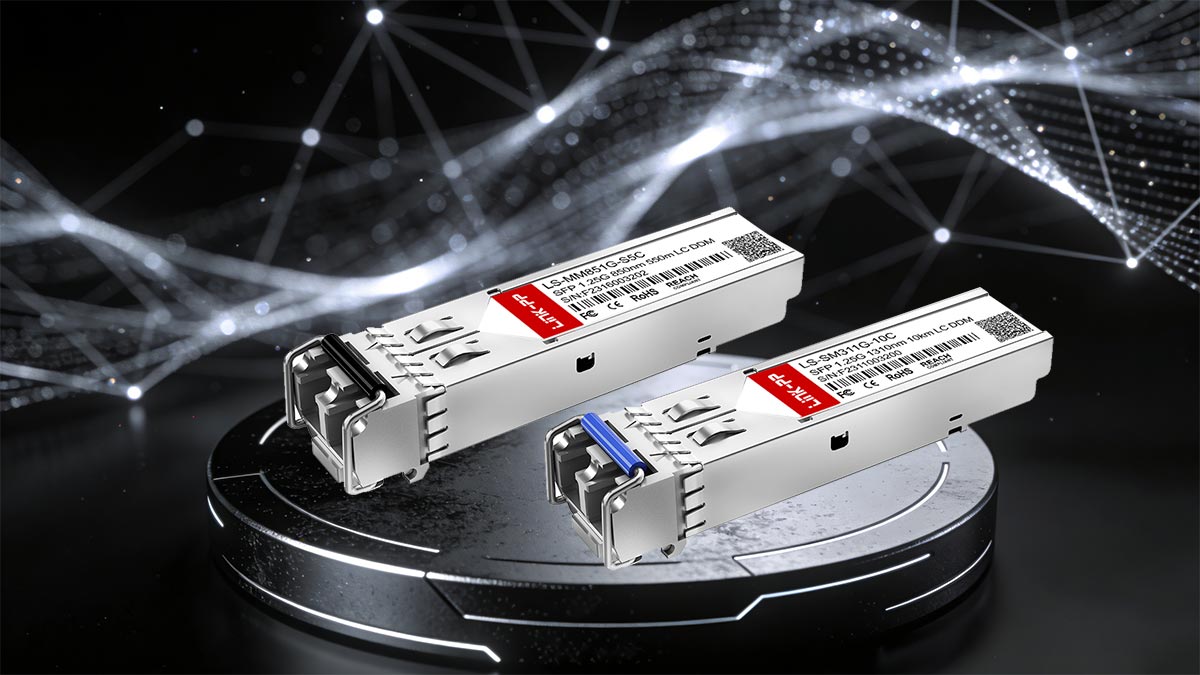
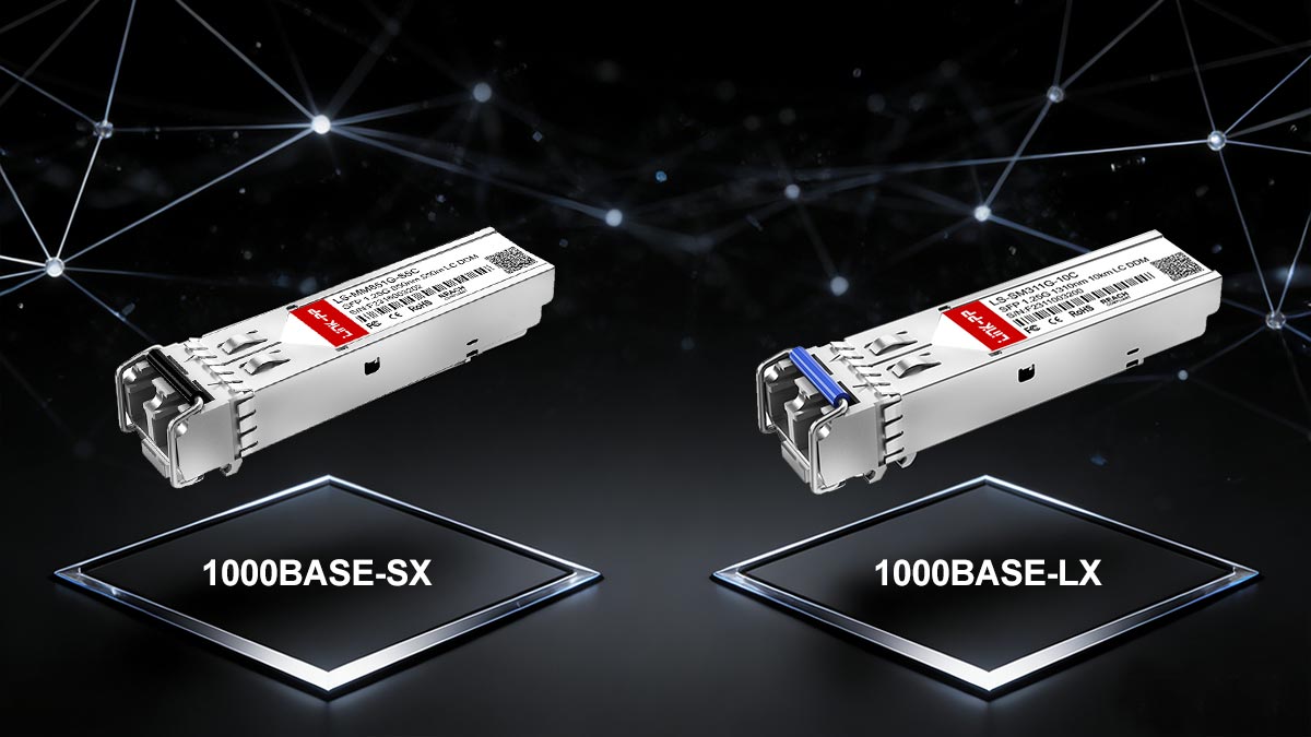
1000BASE-SX and 1000BASE-LX are Ethernet standards defined under IEEE 802.3 for Gigabit Ethernet over fiber optic cabling. Both deliver 1Gbps data rates but differ primarily in wavelength, supported fiber type, and transmission distance. Together, they enable flexible and scalable network designs from short-range data center links to long-distance campus connections.
Overview of 1000BASE-SX vs 1000BASE-LX Standard
The 1000BASE-SX standard operates at 850nm and is designed for use over multimode fiber (MMF). It is typically deployed within buildings, such as connecting switches or servers in data centers, due to its economical cost and shorter transmission range.
In contrast, 1000BASE-LX operates at 1310nm and supports both single-mode fiber (SMF) and certain grades of MMF with mode-conditioning patch cords. LX transceivers are ideal for longer reach links, such as inter-building or campus backbone connections, where optical signal loss over distance must remain minimal.
Typical Reach: 550m vs 10km Explained
The key practical difference between these two standards lies in transmission distance. 1000BASE-SX can typically reach up to 550m on high-quality OM2 multimode fiber, making it suitable for short interconnects and LAN environments. By comparison, 1000BASE-LX can extend up to 10km over single-mode fiber due to lower signal attenuation and better optical efficiency at the 1310nm wavelength.
This reach flexibility allows network designers to choose the appropriate standard based on link length, budget constraints, and fiber infrastructure — balancing cost with performance and scalability across different deployment environments.
? Key Technical Differences Between 1000BASE-SX/LX
While both 1000BASE-SX and 1000BASE-LX are Gigabit Ethernet standards designed for fiber-optic transmission, they differ in several key aspects that determine performance, cost, and deployment environments. The main distinctions lie in the operating wavelength, fiber compatibility, transmission distance, and implementation cost. 1000BASE-SX is optimized for short-range applications using multimode fiber, while 1000BASE-LX targets long-distance communication over single-mode fiber.
Understanding these differences helps network designers choose the right standard for their specific optical link requirements. The table below summarizes the main technical contrasts:
| Feature |
1000BASE-SX |
1000BASE-LX |
| Wavelength |
850nm |
1310nm |
| Fiber Type |
Multimode fiber (MMF) |
Single-mode fiber (SMF), compatible with MMF via mode-conditioning |
| Typical Reach |
Up to 550m over MMF |
Up to 10km over SMF |
| Optical Component |
VCSEL 850nm |
FP 1310nm |
| Typical Use Case |
Data centers, LANs, short interconnects |
Building-to-building links, campus or MAN connections |
| Relative Cost |
Lower |
Higher |
Wavelength Differences (850nm vs 1310nm)
1000BASE-SX uses an 850nm wavelength, which is well-suited for short-range multimode fiber due to lower cost VCSEL lasers and high modal bandwidth. In contrast, 1000BASE-LX operates at 1310nm, which minimizes attenuation over long distances in single-mode fiber, allowing for extended reach up to 10km. The difference in wavelength also influences component design and connector considerations.
Fiber Type Compatibility (MMF vs SMF)
1000BASE-SX is optimized for multimode fiber, where larger core diameters (50μm or 62.5μm) allow simpler and cheaper optical components. However, it is limited by modal dispersion over longer distances. 1000BASE-LX typically operates over single-mode fiber (9μm core), providing much lower attenuation and higher precision for long-range links. When LX transceivers are used with MMF, a mode-conditioning patch cord is required to prevent differential mode delay and maintain reliable signal transmission.
Transmission Distance Capabilities
Transmission reach is where these two standards diverge most noticeably. 1000BASE-SX can reliably transmit up to 550m on OM2 multimode fiber, making it well-suited for short-range network segments like server rooms or data center racks. 1000BASE-LX extends this reach up to 10km on single-mode fiber, supporting metropolitan or campus-scale deployments where optical loss must be minimized across longer links.
Cost and Deployment Considerations
From a cost perspective, 1000BASE-SX systems are generally cheaper to deploy, thanks to the lower price of MMF cabling and VCSEL-based optical modules. They also simplify installation in shorter environments. 1000BASE-LX, while more expensive due to SMF components and FB laser sources, offers scalability for growing network infrastructures that demand extended coverage. Organizations often weigh these cost differences against long-term performance and distance needs when planning fiber network upgrades.
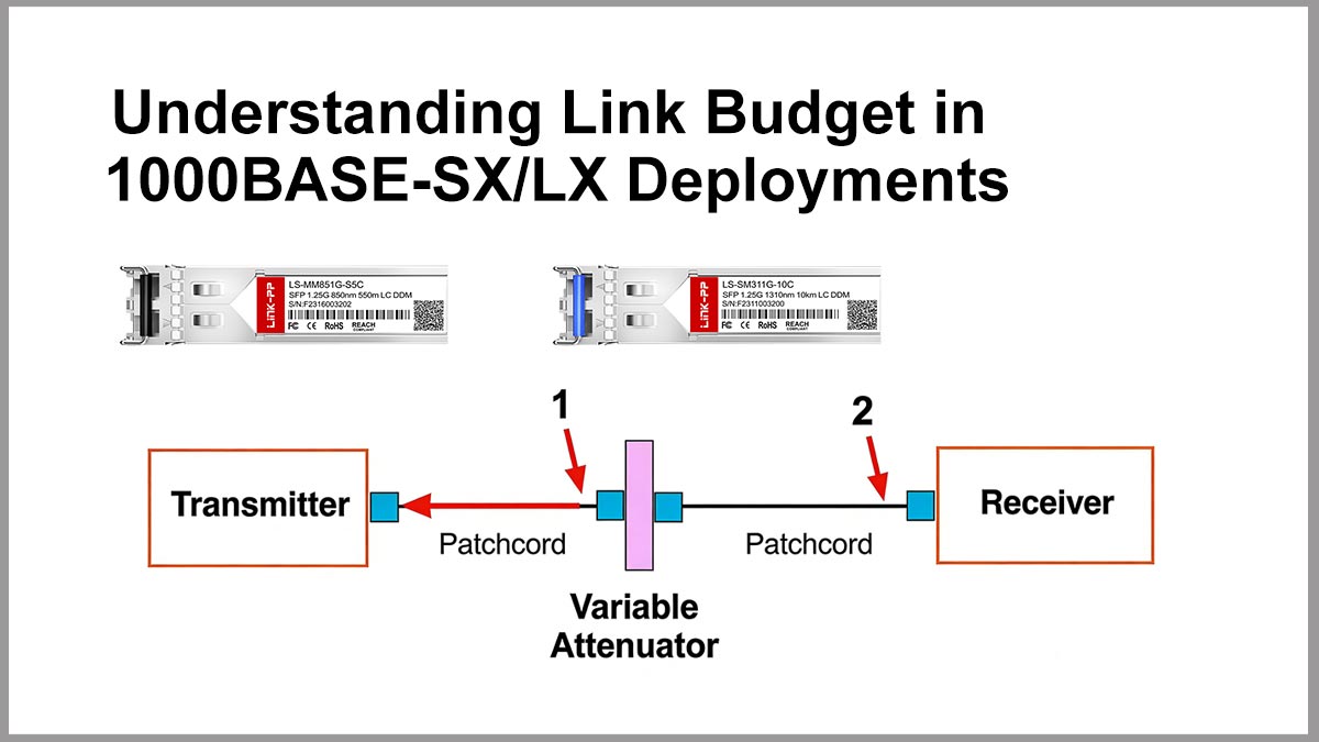
? Understanding Link Budget in 1000BASE-SX/LX Deployments
Link budget is a critical factor in determining whether a 1000BASE-SX/LX fiber link can operate reliably over a given distance. It accounts for the total optical power available versus the total loss in the link. Proper link budget planning ensures stable transmission, minimizes signal degradation, and prevents unexpected network failures.
Definition of Optical Link Budget
An optical link budget is the calculated difference between the transmitter’s output power and the minimum receiver sensitivity for a given link, expressed in decibels (dB). It represents the total allowable loss that the optical path can introduce while still maintaining error-free communication. In practical terms, the link budget indicates the maximum attenuation that your fiber, connectors, splices, and other components can add before the signal becomes unusable.
Components of Power Loss in Fiber Links
Power loss in a 1000BASE-SX/LX link comes from several accumulative sources along the optical path. The largest contributor is usually fiber attenuation, which depends on fiber type, wavelength, and total distance. Additional losses come from connector insertion loss, splice loss, patch panels, and any passive components, such as splitters or multiplexers that may sit between the two transceivers.
Transmit Power vs Receiver Sensitivity
Every 1000BASE-SX/LX transceiver specifies a transmit power range and a receiver sensitivity range in dBm. The minimum transmit power and minimum receiver sensitivity are the most critical values for link budget calculations, because they define the worst-case operating conditions. By subtracting the receiver sensitivity from the minimum transmit power, you obtain the available optical budget, which must be greater than the total calculated link loss for the link to operate reliably.
Safety Margins in Real-World Networks
In real deployments, engineers do not design links to sit exactly at the theoretical edge of the budget. Instead, they reserve a safety margin — often several dB — to account for aging optics, fiber degradation, additional connectors added later, and environmental variations. This margin helps ensure that 1000BASE-SX/LX links remain stable over time, even as components wear and minor imperfections accumulate, reducing the risk of unexpected link flaps or increasing error rates.
? 1000BASE-SX/LX Power Budget Specifications and Standards
Understanding the power budget specifications of 1000BASE-SX/LX is essential for ensuring reliable optical link performance across different distances and fiber types. These standards, defined by IEEE 802.3, establish the allowable limits for transmitter output, receiver sensitivity, and total link loss. By adhering to these specifications, network designers can accurately predict whether a fiber link will operate within acceptable margins.
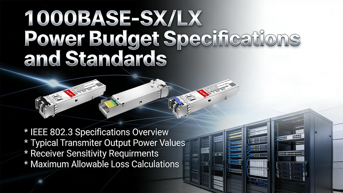
IEEE 802.3 Specifications Overview
The 1000BASE-SX and 1000BASE-LX standards are defined under Clause 38 of the IEEE 802.3 framework. These specifications establish the physical layer (PHY) requirements for optical fiber transmission, focusing on maintaining a Bit Error Rate (BER) of less than 10⁻¹². While 1000BASE-SX is optimized for short-wavelength (850nm) transmission over Multi-Mode Fiber (MMF), 1000BASE-LX is designed for long-wavelength (1310nm) operation, supporting both Single-Mode Fiber (SMF) and MMF to bridge the gap between local and campus-wide networks.
Typical Transmitter Output Power Values
Transmitter output power (Tx Power) represents the amount of optical energy launched into the fiber. For 1000BASE-SX modules (such as GLC-SX-MM-RGD), the average launch power typically ranges from -9.5dBm to -3dBm. 1000BASE-LX modules (such as GLC-LX-SM-RGD) share a similar standard range (often -9.5 to -3dBm for SMF), though they are designed with higher precision lasers (FP or DFB) to ensure signal stability over longer reaches. It is important to note that if the Tx power is too high, it can saturate the receiver, whereas power below the minimum threshold will fail to bridge the target distance.
Receiver Sensitivity Requirements
Receiver Sensitivity is the minimum level of optical power required by the photodetector to accurately decode the signal.
- 1000BASE-SX: Generally requires a minimum sensitivity of approximately -17dBm.
- 1000BASE-LX: Due to the challenges of long-distance attenuation, these receivers are typically more sensitive, often rated down to -19dBm or -20dBm.
The difference between the actual received power and the receiver's sensitivity limit is what determines whether the link remains operational or experiences packet loss.
Maximum Allowable Loss Calculations
The maximum allowable loss, or optical link budget, is calculated as the difference between the minimum transmitter output power and the receiver sensitivity:
- Link Budget = Tx (min) – Rx (min)
For example:
- If Tx (min) = –9.5dBm and Rx (min) = –17dBm,
- Then the maximum allowable loss is approximately 7.5dB.
This loss budget must account for all sources of attenuation in the link, including fiber attenuation, connector losses, splice losses, and any additional safety margins.
- For 1000BASE-SX, this budget supports shorter distances due to higher attenuation in MMF at 850nm.
- For 1000BASE-LX, lower attenuation at 1310nm allows the same or similar power budget to support significantly longer distances (up to 10km on SMF).
In real-world deployments, engineers typically include an additional safety margin (e.g., 2-3dB) to ensure long-term reliability and accommodate aging components or environmental variations.
? Calculating Link Budget for 1000BASE-SX/LX Networks
Accurately calculating the link budget for 1000BASE-SX/LX networks is critical to ensuring stable and error-free data transmission. By accounting for all sources of signal loss along the optical path, engineers can determine whether a link will meet performance requirements over distances ranging from 550m to 10km. A systematic approach to link budget calculation helps prevent underperforming links and reduces deployment risks.
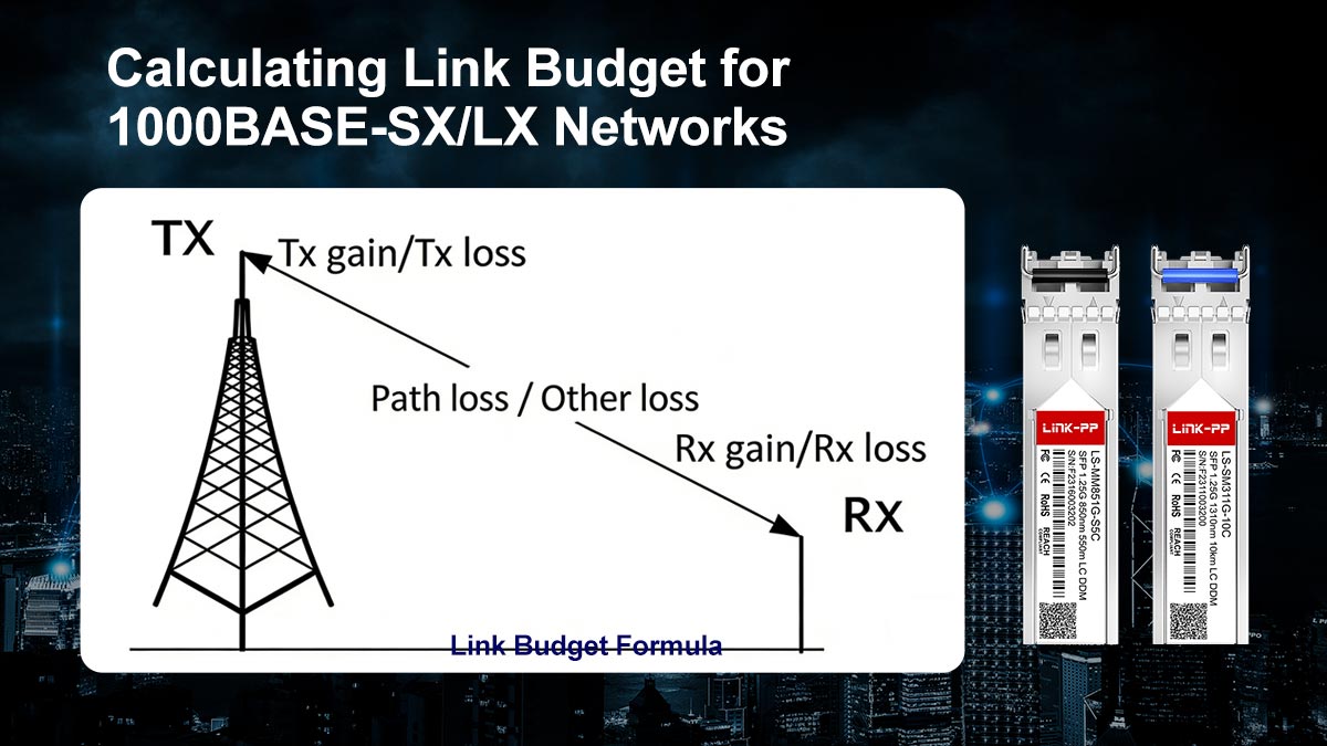
Step-by-Step Link Budget Formula
The optical link budget is calculated using a straightforward formula:
- Link Budget (dB) = Transmitter Output Power (min) – Receiver Sensitivity (min)
To determine whether a link is viable, compare the available link budget to the total estimated loss:
- Total Link Loss (dB) = Fiber Loss + Connector Loss + Splice Loss + Additional Margins
A link is considered operational if:
- Available Link Budget ≥ Total Link Loss
In practice, designers use worst-case values (minimum transmit power and maximum losses) to ensure reliability under all conditions.
Estimating Fiber Attenuation
Fiber attenuation is one of the primary contributors to signal loss and depends on both wavelength and fiber type:
- 1000BASE-SX (850nm, MMF): Typically 2.5 to 3.5dB/km
- 1000BASE-LX (1310nm, SMF): Typically 0.35 to 0.5dB/km
To estimate fiber loss:
- Fiber Loss (dB) = Attenuation (dB/km) × Distance (km)
For example, a 0.55km MMF link at 3dB/km results in approximately 1.65dB of fiber loss. Lower attenuation in single-mode fiber is a key reason why LX supports much longer distances.
Connector and Splice Loss Considerations
In addition to fiber attenuation, every physical connection introduces insertion loss:
- Connector loss: Typically 0.2 to 0.5dB per connector pair
- Splice loss: Typically 0.05 to 0.3dB per splice
A typical link may include multiple connectors (e.g., patch panels, transceiver interfaces) and possibly splices in longer runs. These losses must be carefully counted:
- Total Connection Loss = (Number of Connectors × Loss per Connector) + (Number of Splices × Loss per Splice)
Poor-quality connectors, contamination, or misalignment can significantly increase loss beyond nominal values.
Example Calculation for 550m and 10km Links
To better understand how link budget calculations work in practice, the following examples show how they are used to assess link feasibility across different deployment distances.
? Example 1: 1000BASE-SX over 550m (MMF)
- Distance: 0.55km
- Fiber Attenuation: 3dB/km → 1.65dB
- Connectors: 2pairs × 0.5dB → 1.0dB
- Splices: None
Total Loss = 1.65 + 1.0 = 2.65dB
With a typical link budget of 7.5dB, this link has ample margin (4.85dB), indicating reliable operation.
? Example 2: 1000BASE-LX over 10km (SMF)
- Distance: 10km
- Fiber Attenuation: 0.4dB/km → 4.0dB
- Connectors: 2 pairs × 0.5dB → 1.0dB
- Splices: 2 × 0.2dB → 0.4dB
Total Loss = 4.0 + 1.0 + 0.4 = 5.4dB
With a similar link budget (7.5dB), the remaining margin (2.1dB) is tighter but still acceptable. Adding a safety margin is recommended to ensure long-term stability.
? How to Optimize Link Budget in 1000BASE-SX/LX Deployments
Optimizing the optical link budget ensures that 1000BASE-SX/LX connections operate reliably within their specified power margins. Even small inefficiencies — such as connector loss, fiber imperfections, or misalignment — can degrade performance and cause intermittent link failures. Maintaining optimal conditions requires careful attention to component quality, installation practices, and ongoing verification of optical performance.
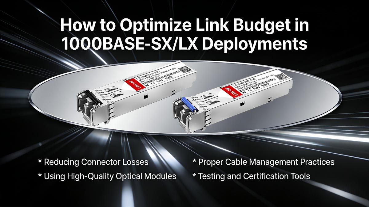
Reducing Connector Losses
Connector loss is one of the most common and controllable sources of attenuation in fiber optic links. Each connector interface introduces insertion loss, and poor handling can significantly increase it beyond expected values. To minimize connector loss, it is critical to use high-quality connectors with precise polishing (e.g., UPC or APC finishes) and to ensure all connectors are properly cleaned before installation.
Dust, oil, and microscopic debris on connector end faces can cause significant signal degradation. Therefore, using proper inspection tools and cleaning kits (such as lint-free wipes and fiber cleaning pens) is essential. Additionally, reducing the number of connector pairs in a link — by simplifying patch panel designs or avoiding unnecessary cross-connects — can further improve the overall link budget.
Using High-Quality Optical Modules
The quality of optical transceiver modules plays a crucial role in maintaining a strong and stable link budget. High-quality modules typically offer more consistent transmit power levels and better receiver sensitivity, reducing the risk of marginal performance.
When selecting optical modules, it is important to ensure they comply with IEEE 802.3 standards and are tested for interoperability with the target networking equipment. Lower-cost or poorly manufactured modules may exhibit wider performance tolerances, leading to unpredictable results. Investing in reliable transceivers — whether OEM or well-certified third-party compatible modules — can help maintain a healthier power margin and reduce long-term maintenance issues.
Proper Cable Management Practices
Effective cable management is often overlooked but has a direct impact on link performance. Excessive bending, tight cable routing, or physical stress on fiber cables can increase attenuation and even cause permanent damage.
To optimize performance, installers should follow recommended bend radius guidelines for both multimode and single-mode fibers. Cable trays, management panels, and proper labeling should be used to organize fiber paths and prevent accidental strain. Avoiding sharp bends and ensuring smooth routing helps maintain consistent signal transmission and preserves the designed link budget.
Testing and Certification Tools
Testing and certification are essential steps in verifying and maintaining an optimized link budget. Tools such as Optical Power Meters (OPM), Light Sources, and Optical Time Domain Reflectometers (OTDR) allow technicians to measure actual link loss and identify problem areas.
Certification testing ensures that the installed link meets design specifications and industry standards. Regular testing can also detect gradual degradation over time, such as connector wear or fiber aging. By incorporating testing into both deployment and maintenance phases, network operators can proactively address issues and ensure the link continues to operate within acceptable power margins.
? 1000BASE-SX/LX Transceiver Selection Guide for Buyers
Selecting the right 1000BASE-SX or 1000BASE-LX transceiver module is critical to achieving optimal link performance and long-term network stability. The choice depends not only on transmission distance and fiber type but also on hardware compatibility, quality assurance, and cost considerations. A thoughtful evaluation helps prevent link mismatches, signal degradation, or unnecessary over-specification.
Choosing Between SX and LX Transceiver Modules
The key decision point lies in understanding the intended reach and fiber infrastructure.
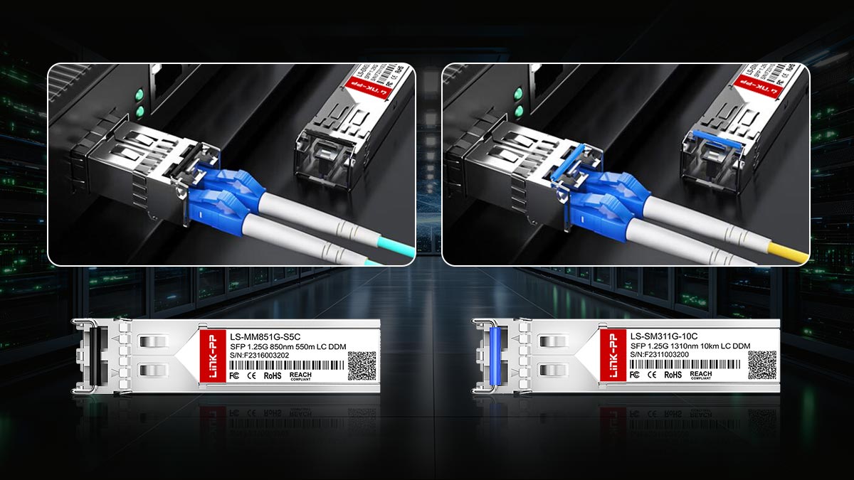
1000BASE-SX modules — such as the LINK-PP LS-MM851G-S5C SFP-1G-SX — operate over 850nm wavelength and are best suited for short-range multimode fiber links, typically inside data centers, server rooms, or enterprise LAN environments. They support up to 550m over OM2 multimode fiber. SX optics are cost-effective, compact, and energy-efficient — ideal when the infrastructure uses existing MMF cabling.
The 1000BASE-LX — for example, the LINK-PP LS-SM311G-10C SFP-1G-LX — functions at 1310nm wavelength, designed for single-mode fiber (SMF) supporting up to 10km reach. LX modules are the right choice for connecting buildings on campus networks, linking distribution frames, or extending metro access networks. Some LX transceiver includes dual compatibility mode to support MMF runs with mode-conditioning patch cables, offering flexibility in mixed environments.
When selecting between the two, consider both the present network design and future scalability needs. 1000BASE-LX provides greater distance margin, but if the network primarily handles short indoor links, 1000BASE-SX may yield better cost-to-performance efficiency.
Compatibility with Switches and Routers
Compatibility is another crucial factor when selecting 100BASE-SX/LX transceivers. Not all modules are universally compatible with every switch or router, as many vendors implement proprietary coding or firmware restrictions.
Before purchasing, it is important to verify that the chosen transceiver is supported by the target equipment. This includes checking form factors, supported standards, and vendor compatibility lists. Using incompatible modules may result in the device failing to recognize the transceiver or operating with limited functionality.
Many network operators choose vendor-coded or multi-vendor-compatible transceivers that are pre-programmed to work with specific brands such as Cisco, Juniper, or Arista. Ensuring compatibility in advance reduces deployment delays and avoids unnecessary troubleshooting.
Third-Party vs OEM Transceivers
The debate between using OEM (Original Equipment Manufacturer) and third-party 1000BASE-SX/LX optical transceivers centers on cost, warranty, and reliability. OEM transceivers are certified, tightly integrated with the vendor’s platform, and often backed by full technical support, but they come at a premium — sometimes two to three times the cost of equivalent third-party options.
Reputable third-party brands (like LINK-PP) offer transceivers fully compliant with IEEE 802.3z and MSA standards, providing comparable performance and quality assurance. They typically undergo rigorous testing for signal integrity, temperature tolerance, and interoperability, ensuring reliability across vendor networks.
For budget-conscious enterprises or scalability projects requiring hundreds of ports, certified third-party transceivers can deliver significant savings without compromising robustness. Still, buyers should source from trusted suppliers that provide full compatibility testing and warranty support to safeguard network stability.
? Key Takeaways for 1000BASE-SX/LX Link Budget Planning
Successful link budget planning for 1000BASE-SX/LX deployments starts with selecting the right standard based on distance and fiber type. SX is best suited for MMF short-range optics applications, while LX is ideal for longer distances over SMF. Using conservative calculations — factoring in fiber attenuation, connector loss, and safety margins — helps ensure the link remains reliable under real-world conditions.
Equally important is the quality of components and installation practices. High-performance transceivers, low-loss connectors, and proper cable management can significantly improve overall link stability. Minimizing unnecessary connections and maintaining clean fiber interfaces will help preserve optical power and reduce long-term maintenance issues.
Finally, always validate your design through proper testing and choose trusted suppliers for your optical components. For dependable optical networking solutions that meet IEEE and MSA standards, consider high-quality transceiver modules from the LINK-PP Official Store. Their verified 1000BASE-SX and 1000BASE-LX modules deliver stable performance and wide compatibility for short-haul (up to 550m) and long-haul (up to 10km) applications.


