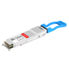
In modern Ethernet networks, optical transceivers are often labeled with short designations that indicate how far a signal can reliably travel. Among the most common are SR LR, two terms that show up everywhere — from switch ports in data centers to uplinks between buildings. If you’ve ever wondered why one module is recommended for a few hundred meters while another is used for tens of kilometers, the difference usually starts with SR LR.
Understanding SR/LR is essential for making the right choices in cabling, cost, and deployment. These designations affect not only transmission distance, but also wavelength, fiber type, and overall network planning. This article breaks down what SR/LR mean, how they differ, and how to select the right optical module for your network.
✳️ What Are SR/LR Optical Designations

SR LR are shorthand labels used on optical transceivers to indicate a “reach class” — in other words, the link distance the module is designed for under standard conditions. In most Ethernet optics, SR targets short links, while LR targets longer links. These labels also hint at the typical wavelength and fiber type used, making SR/LR a quick way to narrow down the right module before diving into datasheets.
Definition of SR and LR in Optical Modules
SR (Short Reach) and LR (Long Reach) are optical designations commonly used across various module types (such as SFP+/SFP28, QSFP/QSFP28). They are not brand-specific; they are industry conventions that help communicate intended transmission reach.
In general, SR modules are optimized for shorter distances and are most often associated with 850nm operation over multimode fiber (MMF). LR modules are optimized for longer distances and are most often associated with 1310nm operation over single-mode fiber (SMF). While exact distances vary by standard and data rate, the SR/LR label is meant to quickly distinguish “short” versus “long” deployments in real networks.
Why SR/LR Modules Matter in Networking
Choosing between SR/LR transceivers impacts more than just how far data travels — it shapes the entire network’s design, cost, and efficiency.
- Performance and Reliability: Using the correct module prevents signal loss and ensures consistent throughput.
- Infrastructure Compatibility: SR and LR transceiver modules align with different fiber types and connector standards, affecting cabling infrastructure.
- Cost Optimization: SR fiber optic SFP module generally costs less, making it ideal for dense, short-range deployments; LR SFP transceiver justifies its higher cost in long-distance backbone links.
Common Use Cases for SR/LR Modules
SR and LR are typically chosen based on where the link lives and what fiber is already installed.
SR module is most common for short, dense connectivity inside facilities — like switch-to-server connections, switch-to-switch links within the same rack/row, or intra–data hall runs where MMF is widely deployed. It’s often the go-to option when distance is clearly limited and cost efficiency matters.
LR module is commonly used for longer structured cabling routes — such as connections between floors, between network rooms, or between buildings on a campus. It also becomes the default when an organization prefers SMF as a long-term standard because it supports longer reaches and broader upgrade paths as speeds increase.
✳️ Key Differences Between SR/LR Optical Modules
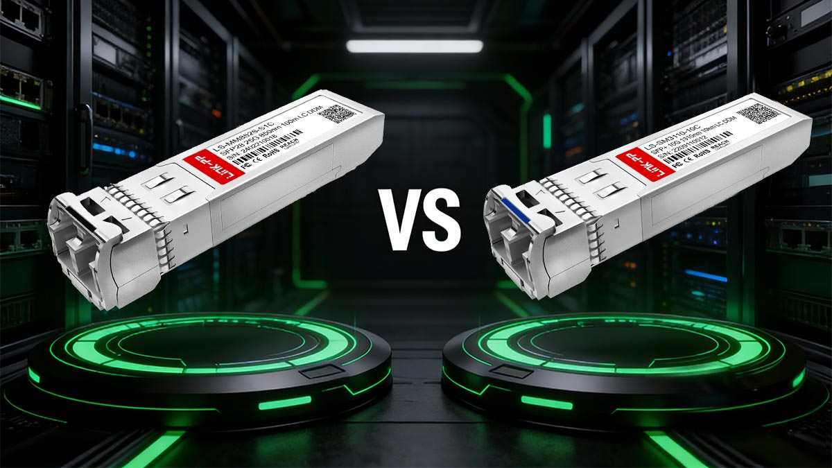
While SR/LR optical modules serve similar functions in transmitting data over fiber, they differ significantly in distance capability, wavelength, fiber requirements, and cost structure. SR modules are optimized for high-speed, short-distance connections within facilities, while LR modules are built for stable long-distance transmission between sites. These differences influence network design choices, fiber infrastructure investment, and overall scalability.
To better illustrate these distinctions, the following table compares the key parameters of SR LR optical modules.
| Feature |
SR |
LR |
| Typical Distance Range |
Up to 300m |
Up to 10km or more |
| Wavelength |
850nm |
1310nm |
| Fiber Type |
Multi-mode fiber (MMF) |
Single-mode fiber (SMF) |
| Typical Applications |
Intra-data center, short links |
Inter-data center, campus links |
| Cost |
Lower |
Higher |
| Signal Type |
Higher modal dispersion |
Lower attenuation and dispersion |
| Deployment Complexity |
Easier installation and testing |
Requires precise alignment and maintenance |
Transmission Distance Comparison
The most fundamental difference between SR and LR modules lies in how far they can transmit data without signal degradation. SR modules are typically limited to a few hundred meters, ideal for short connections within a rack or between nearby switches. Their shorter range results from the higher attenuation and dispersion of signals over multi-mode fibers.
LR modules, on the other hand, extend transmission distances up to 10km or more using single-mode fibers that minimize signal loss. These modules enable network links across campuses, data center interconnects, or metro networks. The ability to sustain long distances comes at a higher cost but offers greater flexibility and scalability for large-scale deployments.
Wavelength and Signal Characteristics
SR and LR modules operate at different optical wavelengths, affecting their transmission behavior and performance. SR modules typically use an 850nm VCSEL laser, which is well-suited for MMF and cost-effective short-range connectivity. However, this wavelength is more prone to modal dispersion, limiting the effective distance of transmission.
By contrast, LR modules use a 1310nm DFB laser, which transmits signals with reduced attenuation and greater stability over long distances. This wavelength is ideal for SMF, offering a cleaner signal with minimal distortion. The trade-off is a higher manufacturing and alignment cost but significantly improved optical performance for extended links.
Fiber Type Requirements (MMF vs SMF)
SR modules require multi-mode fiber (MMF), which features a larger core diameter that allows multiple light paths. This makes MMF easier to handle and install, especially in short-range networks where cost efficiency and compact connections are primary concerns. However, multimode’s higher dispersion limits its performance over longer distances.
In contrast, LR modules use single-mode fiber (SMF), which has a smaller core that transmits a single light path. This structure greatly reduces dispersion and signal loss, enabling reliable data transfer over much longer distances. SMF installation demands higher precision in alignment and connector handling, but it provides superior long-term performance for large-scale or distributed networks.
Cost and Deployment Considerations
Cost considerations often guide the decision between SR and LR modules. SR modules are generally more affordable in both transceiver and cabling costs, making them ideal for dense server environments and short connectivity requirements. Their simple installation and maintenance further reduce operational expenses.
LR modules come with higher upfront costs due to the more advanced optics and single-mode fiber required. Yet, they deliver greater value for networks that need long-distance or inter-campus connectivity. For organizations seeking future scalability, this investment ensures better bandwidth capacity and fewer frequent infrastructure upgrades.
✳️ SR/LR Transmission Distances Explained
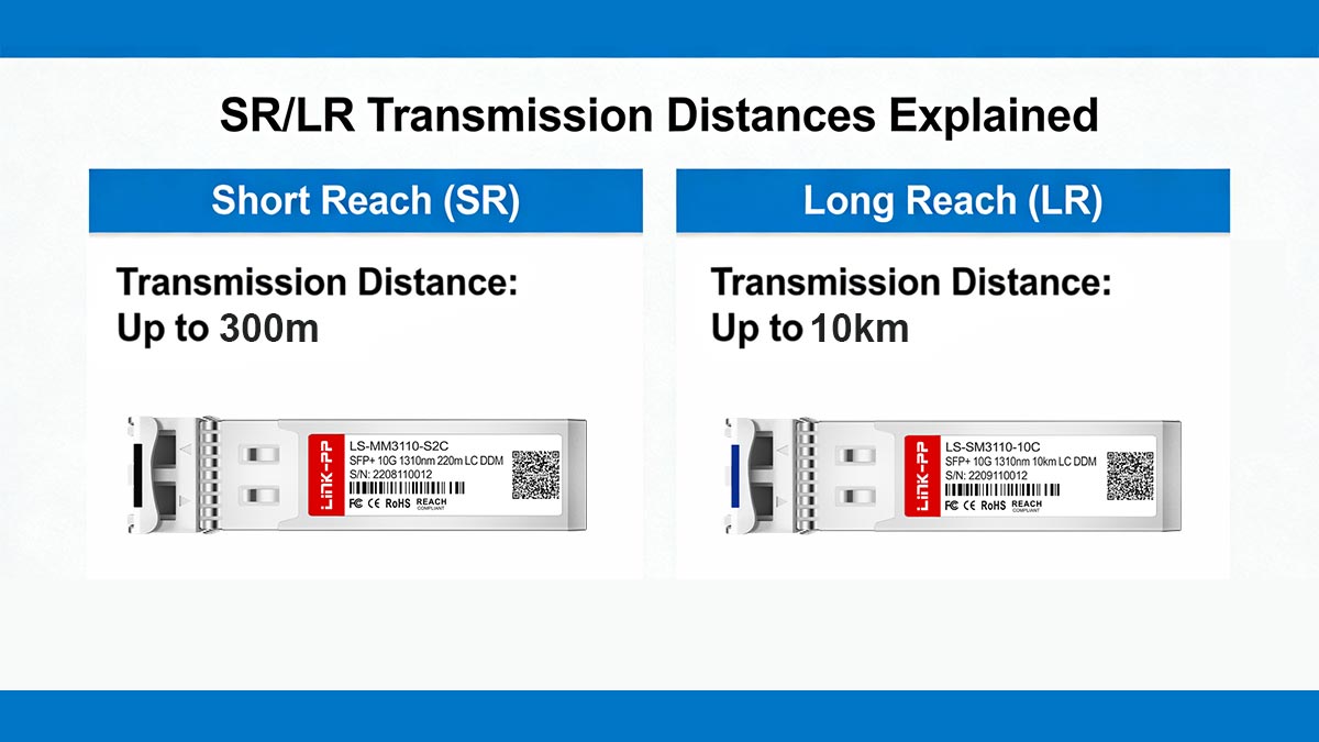
The effective transmission distance of optical modules determines how far data can travel while maintaining signal integrity and performance. SR and LR modules use different fiber types, wavelengths, and optical power levels to achieve their target ranges. Understanding their typical distance capabilities — as well as the environmental and technical factors that influence them — is essential for designing efficient, reliable optical networks.
Typical Distance Range for SR Module
SR modules are typically used for short-distance communication, most commonly within data centers. Depending on the data rate and fiber grade (such as OM3, OM4, or OM5), SR modules usually support distances ranging from 100 meters to 300 meters. For example, an SFP 10G SR module can reach up to 300m on OM3 multimode fiber, while higher-speed modules (e.g., 40G QSFP+/100G QSFP28 SR) often have shorter maximum distances.
These distance limits are mainly due to modal dispersion in multimode fiber, where multiple light paths cause signal spreading over distance. As data rates increase, this effect becomes more pronounced, reducing the maximum achievable reach. This is why SR is best suited for compact environments with clearly defined, short link requirements.
Typical Distance Range for LR Module
LR modules are designed for long-distance transmission over single-mode fiber. A standard LR module typically supports distances of up to 10km or 20km, though some extended LR variants (such as QSFP28-ER4 or QSFP-100G-ZR4-S modules) can reach 40km, 80km, or more depending on the specification.
The longer reach is possible because single-mode fiber minimizes dispersion and attenuation, allowing signals to travel further with less degradation. This makes LR modules ideal for campus backbones, metro links, and inter-building connections where distance is a key requirement.
Factors That Affect Transmission Distance
While SR and LR modules have defined distance ratings, several real-world factors can influence their actual performance:
- Fiber Quality and Type: The grade and condition of the fiber (e.g., OM3 vs. OM4, OS1 vs. OS2) significantly affect distance reach.
- Connector and Splice Loss: Poor connections lead to optical signal attenuation, reducing maximum distance.
- Signal Power Budget: Variations in transmitter output and receiver sensitivity determine distance capability.
- Environmental Conditions: Temperature, humidity, and cable bending can all impact signal propagation and create slight performance deviations.
Proper fiber management and adherence to installation best practices can help minimize these losses and maintain optimal transmission quality.
Real-World Distance Performance
In practice, the effective transmission range often differs from theoretical maximums. Data centers typically operate SR links well below the 300m limit to maintain stronger signal margins and simpler cabling routes. For LR modules, while 10km is standard, some advanced implementations — especially with newer optics — can reach 20km or more when paired with higher-quality SMF and amplification techniques.
Network engineers also consider link budgets, testing results, and application-specific performance goals to determine the safe operating range. Balancing these practical considerations ensures reliable data transmission, reduces packet loss, and prolongs the life of the optical infrastructure.
✳️ SR/LR Fiber Types and Compatibility
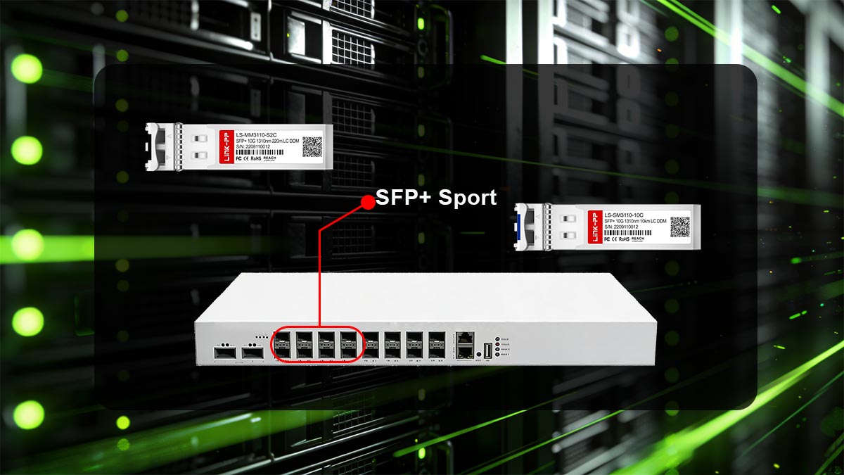
SR/LR optical modules are designed for different fiber environments, so matching the module to the correct fiber type is important for stable performance. In general, SR pairs with multi-mode fiber (MMF), while LR pairs with single-mode fiber (SMF). Compatibility also depends on connector standards, link design, and whether the installed cabling supports the target transmission distance.
Multi-Mode Fiber (MMF) for SR
SR modules are specifically optimized for multi-mode fiber (MMF), which is widely used in short-distance, high-density environments such as data centers. MMF’s larger core allows multiple light modes to propagate simultaneously, making it easier to couple light from the transceiver into the fiber. This design simplifies installation and reduces cost, but it also introduces modal dispersion, which limits transmission distance as data rates increase.
To better understand where MMF fits in SR deployments, consider the following key aspects:
Core Size and Structure:
- Typically 50µm (OM3/OM4/OM5) or 62.5µm (OM1/OM2).
- Larger core enables multiple light paths but increases signal dispersion.
Fiber Grades and Performance:
- OM3/OM4 are standard for modern SR deployments.
- OM5 supports wider wavelength ranges and improved performance for higher speeds.
Deployment Advantages:
- Lower overall cost compared to SMF systems.
- Easier handling and alignment during installation.
- Well-suited for structured cabling within buildings.
In practice, MMF paired with SR modules delivers excellent performance for short links, but careful selection of fiber grade is still necessary to meet distance and speed requirements.
Single-Mode Fiber (SMF) for LR
LR modules are designed to operate over single-mode fiber (SMF), which is fundamentally different from MMF in both structure and performance. With a much smaller core, SMF allows light to travel along a single path, significantly reducing dispersion and enabling long-distance transmission with high signal integrity. This makes it the preferred choice for backbone and inter-building connections.
From a deployment perspective, SMF introduces different technical and operational considerations:
Core Characteristics:
- Core size is typically around 9µm.
- Single propagation mode minimizes distortion and attenuation.
Performance Benefits:
- Supports distances of 10km or more with standard LR modules.
- Maintains signal quality over long spans.
- Better suited for future high-speed upgrades.
Deployment Trade-offs:
- Higher initial cost for optics and components.
- Requires more precise alignment and cleaner connections.
- Often used as a long-term infrastructure investment.
Connector Types and Standards
Beyond fiber type, physical connectivity plays a crucial role in SR LR compatibility. Optical modules must match not only the fiber type but also the connector interface used in the cabling system. Even if the optical specifications are correct, a mismatch at the connector level can prevent proper deployment.
In most environments, the following connector types and standards are commonly encountered:
LC Connectors:
- The most widely used interface for SFP+/SFP28 SR/LR modules.
- Compact design suitable for high-density applications.
MPO/MTP Connectors:
Standards Alignment:
- Most modules follow IEEE specifications for interoperability.
- Consistency across vendors depends on adherence to these standards.
Selecting the correct connector type ensures not only physical compatibility but also efficient use of available fiber infrastructure.
Compatibility Issues and Solutions
Despite standardized designs, compatibility issues with SR LR modules are still common in real-world deployments. These problems often arise from mismatched fiber types, inconsistent components, or overlooked physical constraints, and they can lead to degraded performance or complete link failure.
Typical challenges and their practical solutions include:
Fiber Mismatch Issues:
- SR used with SMF or LR used with MMF can cause severe signal problems.
- Always verify fiber type before module selection.
Connector Incompatibility:
- Mismatched interfaces (e.g., LC vs MPO) prevent proper connection.
- Use appropriate patch cords or conversion solutions when necessary.
Mixed Standards or Environments:
- Combining different data rates or non-standard components can create instability.
- Standardizing optics and cabling across the network reduces risk.
Mitigation Techniques:
- Use mode-conditioning cables when bridging MMF and SMF in legacy setups.
- Perform link testing and validation before full deployment.
- Maintain clean connectors to avoid unnecessary signal loss.
By proactively addressing these compatibility factors, network designers can ensure that SR and LR modules operate as intended, delivering reliable and predictable performance across different deployment scenarios.
✳️ SR/LR Optical Module Standards and Specifications
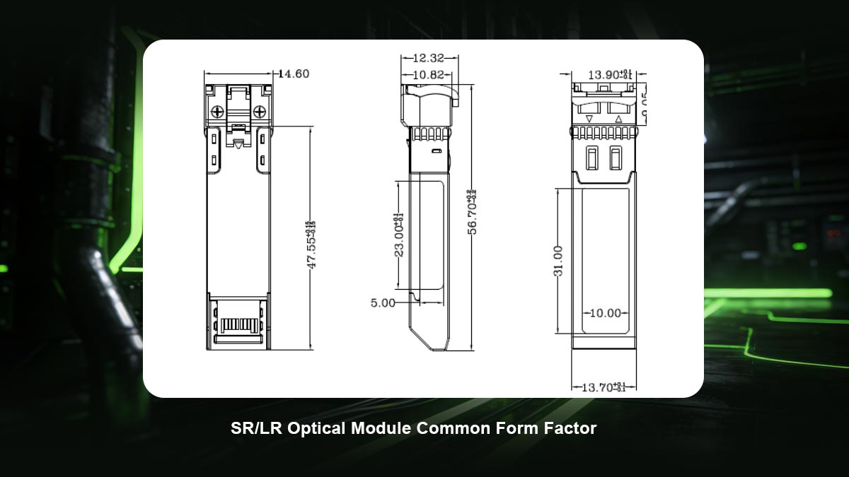
SR LR optical modules adhere to industry-standard specifications that ensure interoperability, performance consistency, and reliable deployment across diverse network equipment. These standards, primarily from IEEE and Multi-Source Agreements (MSA), define electrical, mechanical, and optical parameters for consistent operation. Understanding these specifications helps network engineers select modules that meet specific data rates, form factors, and environmental requirements.
IEEE Standards for SR and LR
The IEEE 802.3 Ethernet standards define SR and LR optics specifications, with 10GBASE-SR covering short-range multimode transmission at 850nm up to 300m, and 10GBASE-LR specifying long-range single-mode operation at 1310nm up to 10km. Higher-speed modules like 25GBASE-SR and 25GBASE-LR extend these to 25Gbps while maintaining similar distance and fiber profiles. These standards ensure predictable performance and vendor interoperability in Ethernet networks.
Common Form Factor
SFP+/SFP28 is the most prevalent form factor for SR/LR 10G modules and 25G transceivers due to its compact size, hot-swappability, and support for duplex LC connectors. For higher speeds like 40G/100G, QSFP+/QSFP28 are common, often using parallel optics for SR variants with MPO connectors. These form factors comply with SFF-8431 and SFF-8472 MSA standards, enabling seamless integration into switches, routers, and servers from multiple vendors.
Data Rates and Performance Metrics
Beyond reach, specs define how the module performs at a given speed — especially as data rates increase and margins shrink. Key metrics typically include transmit optical power, receiver sensitivity, link budget, and signal integrity limits that impact error performance. In SR/LR planning, the most useful way to read these metrics is as a pass/fail envelope: if your total channel loss (fiber + connectors + splices) stays within the module’s supported budget, the link should be stable; if not, you’ll see intermittent errors or link drops even when distance alone seems “within range.”
✳️ How to Choose Between SR/LR Optical Modules
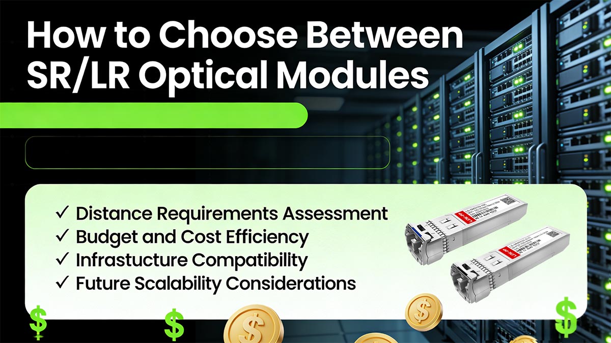
Selecting between SR/LR optical modules requires balancing distance needs, existing infrastructure, budget constraints, and long-term network goals. The right choice optimizes performance while minimizing costs and deployment complexity. A systematic evaluation process ensures reliable connectivity tailored to specific use cases.
Distance Requirements Assessment
The first step in choosing between SR and LR is evaluating the physical distance between devices. SR modules are optimized for short distances, typically within the same rack, row, or data hall, whereas LR modules can span tens of kilometers over single-mode fiber. Accurate distance measurement and consideration of patch panels or splices are essential to ensure that the chosen module will maintain signal integrity without exceeding its specifications.
Budget and Cost Efficiency
Cost is another key factor in selecting SR versus LR. SR modules, paired with multi-mode fiber, are generally less expensive both in optics and cabling infrastructure, making them suitable for dense, short-range environments. LR modules, on the other hand, require single-mode fiber and more precise optics, which increases upfront costs. Choosing the right module involves balancing the immediate expenditure with long-term network requirements and potential upgrades.
Infrastructure Compatibility
Compatibility with existing network infrastructure is critical for a seamless deployment. SR modules require multi-mode fiber and connectors suited for short-distance links, while LR modules depend on single-mode fiber with matching connectors and standards. Assessing current cabling, patch panels, and transceiver form factors ensures that the new modules integrate smoothly without unnecessary re-cabling or adapter usage.
Future Scalability Considerations
Finally, future growth and network scalability should influence the SR/LR decision. LR modules offer greater flexibility for expansion and longer reach as network demands increase, making them suitable for evolving campus or metro networks. SR modules can be ideal in stable, confined environments where high-density short links are sufficient, but planning for future speed upgrades and distance extensions may necessitate LR adoption.
✳️ Installation and Deployment Tips for SR/LR Modules
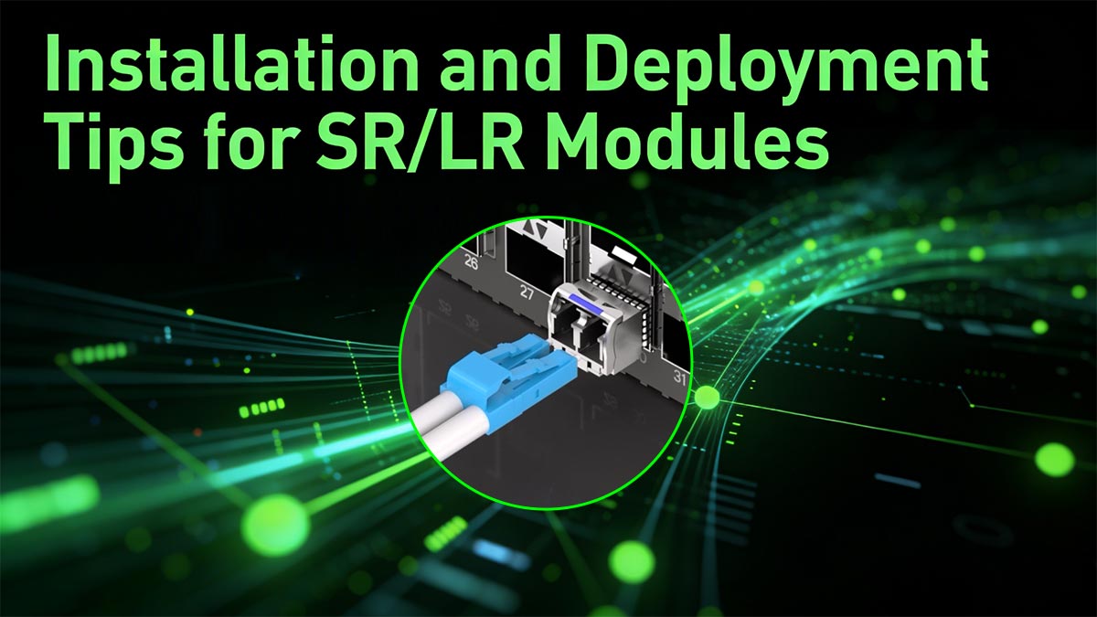
Proper installation and deployment practices are crucial to maximize the performance and lifespan of SR LR optical modules. Even the most advanced modules can experience signal degradation or failure if mishandled, improperly installed, or tested inadequately. Following standardized procedures helps ensure reliable connectivity and reduces maintenance issues over time.
Proper Fiber Handling Practices
Fiber optic cables demand meticulous handling to prevent damage that could degrade signal quality or cause link failures.
- Clean connectors with lint-free wipes and isopropyl alcohol before every connection.
- Avoid tight bends — respect minimum bend radius (typically 10x cable diameter for MMF, 15x for SMF).
- Use proper strain relief and cable management to prevent stress on terminations.
- Store unused fiber optic transceivers capped to block dust and contaminants.
Ensuring Correct Module Selection
Deploying incompatible modules leads to immediate link failures or intermittent performance issues. Verify module specifications match the fiber type, distance requirements, and switch port capabilities before installation. Cross-reference vendor documentation and MSA compliance to guarantee interoperability across equipment brands.
Testing and Validation Procedures
Post-installation testing confirms link integrity and performance margins. Use an optical power meter to measure Tx/Rx levels against module specifications, and an OTDR to identify attenuation points or faults. Validate bit error rates (BER) with a test set and monitor DDM parameters (temperature, voltage, bias current) for anomalies during burn-in testing.
Troubleshooting Common Issues
When links fail to establish, follow a systematic diagnostic approach:
- No Light Detected: Check module seating, power budget, and fiber continuity.
- High BER or CRC Errors: Inspect connectors for contamination and measure insertion loss.
- Intermittent Drops: Verify polarity, temperature extremes, or power supply fluctuations.
- Distance Underperformance: Confirm fiber grade matches module specs (OM3+ for SR, OS2 for LR).
Enable switch port logging and module diagnostics to pinpoint root causes quickly.
✳️ Key Takeaways on SR/LR Optical Designations
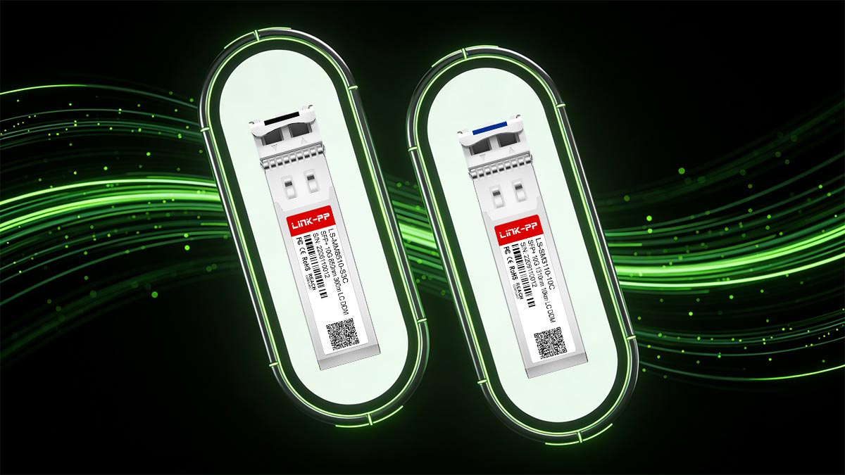
SR modules excel in cost-effective, high-density data center links up to 300m over MMF, while LR modules power campus and metro connections up to 10km+ over SMF. Match modules to distance needs, fiber infrastructure, and budget constraints while prioritizing IEEE standards and MSA compliance for reliable interoperability.
Ready to deploy reliable SR/LR optics transceivers in your network? Visit the LINK-PP Official Store for high-quality, standards-compliant modules with competitive pricing.