As 400G Ethernet networks become the new backbone of hyperscale data centers, AI clusters, telecom aggregation, and high-density enterprise switching, simply installing a QSFP-DD 400G optical module is no longer enough to guarantee stable transmission.
At this speed, even minor signal degradation, insertion loss, lane imbalance, or Forward Error Correction (FEC) instability can quickly turn into packet loss, CRC alarms, or unacceptable latency spikes.
This is why a professional QSFP-DD 400G test solution has become a critical part of modern optical deployment.
Instead of relying only on link-up status or vendor compatibility labels, network engineers now need measurable validation methods to answer several practical questions:
-
Is the 400G QSFP-DD module delivering acceptable Bit Error Rate (BER) performance?
-
Are all eight electrical/optical lanes operating within tolerance?
-
Does the link remain stable under real traffic load and thermal stress?
-
Is FEC masking hidden signal quality problems?
-
Can the module maintain interoperability during breakout or mixed-vendor deployment?
These are not theoretical concerns.
In many real 400G deployments, links may appear “up” while still suffering from silent BER growth, marginal eye closure, intermittent lane errors, or unstable breakout performance that only emerges during sustained production traffic.
Therefore, BER monitoring and link quality verification are now considered the two most important checkpoints in any 400G QSFP-DD module validation workflow.
This article will provide a complete engineering-level guide to building an effective QSFP-DD 400G test solution, including BER measurement principles, link quality assessment methods, common failure symptoms, and recommended validation practices before large-scale deployment.
🚩 What Is a QSFP-DD 400G Test Solution?
A QSFP-DD 400G test solution is a complete validation method used to verify whether a 400G QSFP-DD optical module can deliver stable, low-error, and standards-compliant data transmission before deployment.
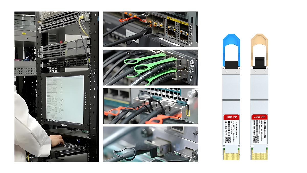
Unlike basic link-up checking, 400G testing focuses on measurable signal performance because QSFP-DD modules use 8 high-speed PAM4 lanes, making them far more sensitive to:
This means a link may appear operational while hidden signal degradation is already affecting long-term reliability.
For this reason, engineers use a dedicated QSFP-DD 400G test solution to evaluate both BER (Bit Error Rate) and overall link quality under real traffic conditions.
QSFP-DD 400G Test Solution at a Glance
|
Test Item
|
What It Verifies
|
Why It Matters
|
|
BER Monitoring
|
Measures raw bit transmission errors
|
Detects hidden signal degradation early
|
|
FEC Analysis
|
Tracks corrected physical layer errors
|
Shows whether the link is relying on error correction
|
|
Optical Power Test
|
Checks TX/RX power and insertion loss
|
Confirms lane optical balance
|
|
Signal Integrity Check
|
Measures jitter, eye quality, and skew
|
Verifies electrical channel stability
|
|
Traffic Stress Test
|
Runs sustained full-load transmission
|
Confirms long-term production reliability
|
|
Breakout Validation
|
Tests 400G to 4×100G lane behavior
|
Ensures stable interoperability
|
Key Elements of a QSFP-DD 400G Test Solution
A professional 400G validation setup usually includes:
-
BER Tester (BERT): measures pre-FEC and post-FEC bit error performance
-
Optical Power Testing: checks TX/RX power, insertion loss, and lane consistency
-
FEC Monitoring: detects hidden corrected errors behind a “link up” status
-
Signal Integrity Analysis: verifies eye quality, jitter, and lane stability
-
Traffic Stress Testing: simulates full-load throughput and breakout operation
Together, these tools determine whether the module can maintain reliable transmission in production networks.
Why It Is More Than a Basic Optical Check
Traditional optical testing only confirms whether the module can establish a connection.
A QSFP-DD 400G test solution goes much deeper by confirming:
-
whether all 8 lanes transmit cleanly,
-
whether BER stays within acceptable thresholds,
-
whether FEC is masking physical layer weakness, and
-
whether the module remains stable during long-duration traffic or breakout use.
In short, it is a pre-deployment risk-control process designed to catch silent 400G link failures before they impact live network performance.
🚩 Why BER Monitoring Matters in 400G Network Validation
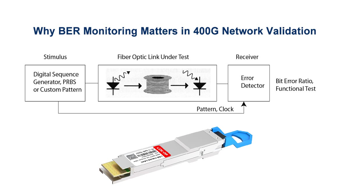
In a QSFP-DD 400G test solution, BER (Bit Error Rate) monitoring is the most direct way to judge whether a 400G optical link is truly stable.
BER shows how many bits are transmitted incorrectly during data transfer.
Because QSFP-DD 400G modules use 8 high-speed PAM4 lanes, even small signal disturbances can create hidden bit errors that are not visible through simple link-up checks.
This means a port can appear operational while the physical layer is already losing transmission margin.
That is why BER is considered the first and most important metric in 400G network validation.
BER Detects Hidden Link Degradation Early
In real deployments, issues such as:
-
fiber attenuation,
-
connector contamination,
-
lane skew,
-
thermal fluctuation,
-
or host-side signal loss
often do not cause immediate link failure.
Instead, they first appear as a gradual rise in bit errors.
BER monitoring helps engineers identify these hidden signal problems before they develop into:
-
CRC alarms,
-
packet retransmission,
-
FEC overload,
-
or unstable throughput.
This makes BER far more reliable than a simple “Link Up” indicator.
Why Pre-FEC BER Matters More Than Link Status
One major challenge in 400G Ethernet is that Forward Error Correction (FEC) can temporarily mask physical layer weakness.
The link may continue forwarding traffic because FEC is correcting corrupted symbols in the background.
However, if the pre-FEC BER continues rising, the channel is operating with reduced safety margin and may fail under:
For this reason, engineers monitor BER not just to confirm connectivity, but to confirm long-term reliability.
BER Is the Fastest Indicator of Overall Link Quality
Compared with packet ping tests or throughput checks, BER is much more sensitive to early optical degradation.
It helps verify:
-
whether all 8 lanes are transmitting cleanly,
-
whether FEC correction remains within tolerance,
-
whether signal quality is stable under load, and
-
whether the module has enough margin for production deployment.
In short, BER monitoring allows engineers to catch silent 400G link problems before they turn into visible network failures.
🚩 How to Measure Link Quality in QSFP-DD 400G Links
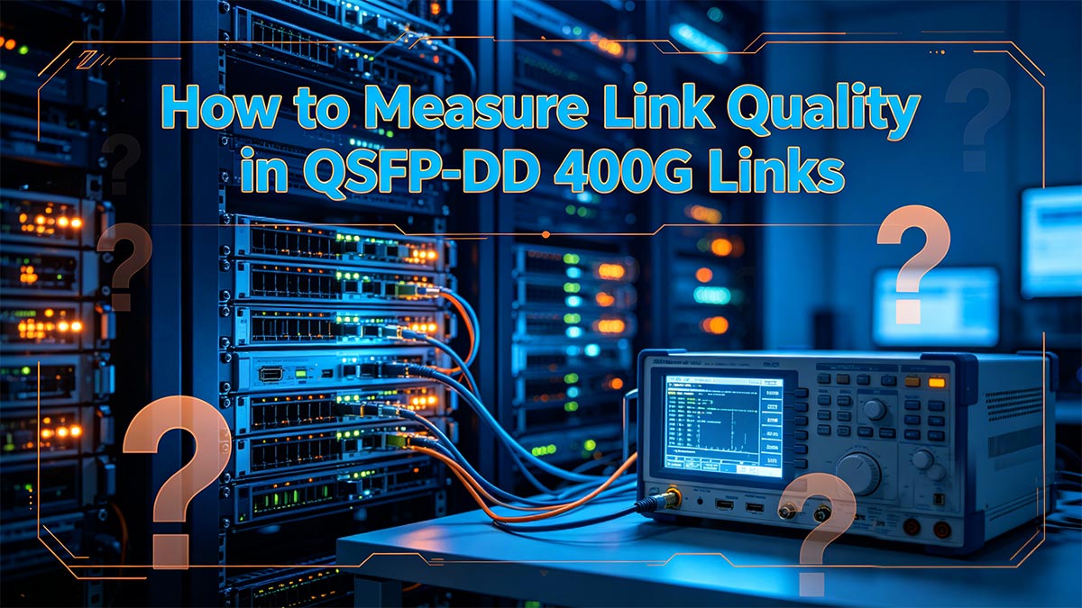
While BER monitoring reveals whether bit errors are occurring, complete link quality testing determines why the errors happen and whether the optical channel has enough performance margin for long-term operation.
In other words, BER tells engineers that a problem exists, while link quality measurement shows how stable the entire QSFP-DD 400G transmission path really is.
Because 400G links rely on high-speed PAM4 signaling across 8 lanes, engineers usually evaluate several parameters together instead of using a single pass/fail test.
1. Optical Power and Insertion Loss Testing
The first step is to confirm whether the transmitter and receiver are operating within the expected optical budget.
This includes checking:
If one lane experiences excessive attenuation or connector reflection, the module may still link up, but BER and FEC correction will gradually increase.
That is why optical power balance is a basic indicator of 400G link health.
2. FEC and Lane Error Monitoring
A healthy QSFP-DD 400G channel should not rely heavily on FEC correction to remain stable.
Engineers therefore monitor:
-
corrected FEC codewords,
-
lane symbol errors,
-
deskew status,
-
pre-FEC BER trend.
If one or more lanes show continuous corrected errors, it usually means the physical signal margin is shrinking even though traffic is still passing.
This is one of the most effective ways to identify hidden lane instability.
3. Signal Integrity Verification
Beyond optical power, engineers also test the electrical quality of the signal itself.
Typical measurements include:
-
eye diagram opening,
-
jitter tolerance,
-
lane skew,
-
channel loss.
Poor signal integrity often comes from:
These factors can create unstable BER behavior even when optical power levels look normal.
4. Full Traffic Stress Testing
A QSFP-DD module should also be tested under sustained full-load traffic rather than only short bench checks.
Traffic generators are used to verify:
-
packet stability at line rate,
-
no burst frame loss,
-
no thermal-triggered BER spikes,
-
stable operation during long-duration transmission.
This step is important because some 400G modules pass static lab tests but become unstable only under continuous throughput pressure.
What Engineers Look for in a Healthy 400G Link
A qualified QSFP-DD 400G link should show:
-
balanced optical power across lanes,
-
low and stable BER values,
-
minimal FEC correction dependency,
-
clean signal integrity performance,
-
no packet instability during stress traffic.
When these conditions are met together, engineers can confirm that the module is not just connected, but production-ready.
🚩 Common Test Scenarios for QSFP-DD 400G Modules
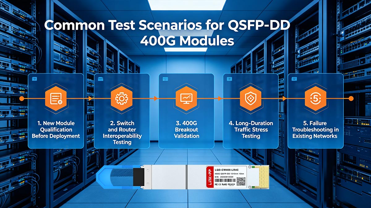
A QSFP-DD 400G test solution is not used only for laboratory certification.
In practice, engineers apply it across several deployment stages to make sure the module can maintain stable performance under different network conditions.
The most common testing scenarios focus on compatibility, traffic stability, and breakout reliability.
1. New Module Qualification Before Deployment
Before installing a 400G QSFP-DD optical module into a production switch, engineers typically verify:
This helps identify factory defects, marginal optics, or shipping damage before the module enters a live network.
2. Switch and Router Interoperability Testing
Not all host platforms handle 400G modules in exactly the same way.
Different switch ASICs, firmware versions, and port calibration settings can affect:
-
signal training,
-
FEC negotiation,
-
EEPROM recognition,
-
thermal reporting.
For this reason, interoperability testing is commonly performed between the QSFP-DD module and target switch/router platforms to confirm stable link establishment.
3. 400G Breakout Validation
One of the most frequent real-world uses of QSFP-DD is 400G to 4×100G breakout.
In this setup, engineers must confirm:
-
each breakout lane negotiates correctly,
-
BER remains balanced across channels,
-
no individual lane shows abnormal FEC correction,
-
long-duration traffic remains stable.
Breakout links often expose lane-specific weaknesses faster than standard native 400G connections.
4. Long-Duration Traffic Stress Testing
Some modules perform normally during short validation but become unstable after hours of continuous traffic due to:
That is why many engineers run sustained line-rate traffic tests to check whether BER or corrected errors increase over time.
5. Failure Troubleshooting in Existing Networks
When a live 400G link shows:
-
intermittent CRC alarms,
-
unexplained packet loss,
-
unstable throughput,
-
or random disconnects,
a QSFP-DD 400G test solution is used to isolate whether the issue comes from:
-
the optical module,
-
the fiber path,
-
the breakout assembly,
-
or the host port.
This makes test validation an important troubleshooting tool as well as a pre-deployment process.
Why These Scenarios Matter
Although all of these scenarios use the same basic metrics—BER, FEC, optical power, and signal integrity—the testing objective changes:
-
qualification checks product readiness,
-
interoperability checks host compatibility,
-
breakout validation checks lane consistency,
-
stress testing checks long-term stability,
-
troubleshooting checks fault location.
Together, they provide a complete view of real QSFP-DD 400G link performance.
🚩 Troubleshooting High BER, FEC Errors, and Unstable Links
Even after a QSFP-DD 400G module successfully links up, engineers may still encounter rising BER values, frequent FEC corrections, or intermittent traffic instability during operation.
These symptoms usually indicate that the optical channel is working with limited signal margin rather than true long-term stability.
A structured troubleshooting process helps identify the root cause faster.
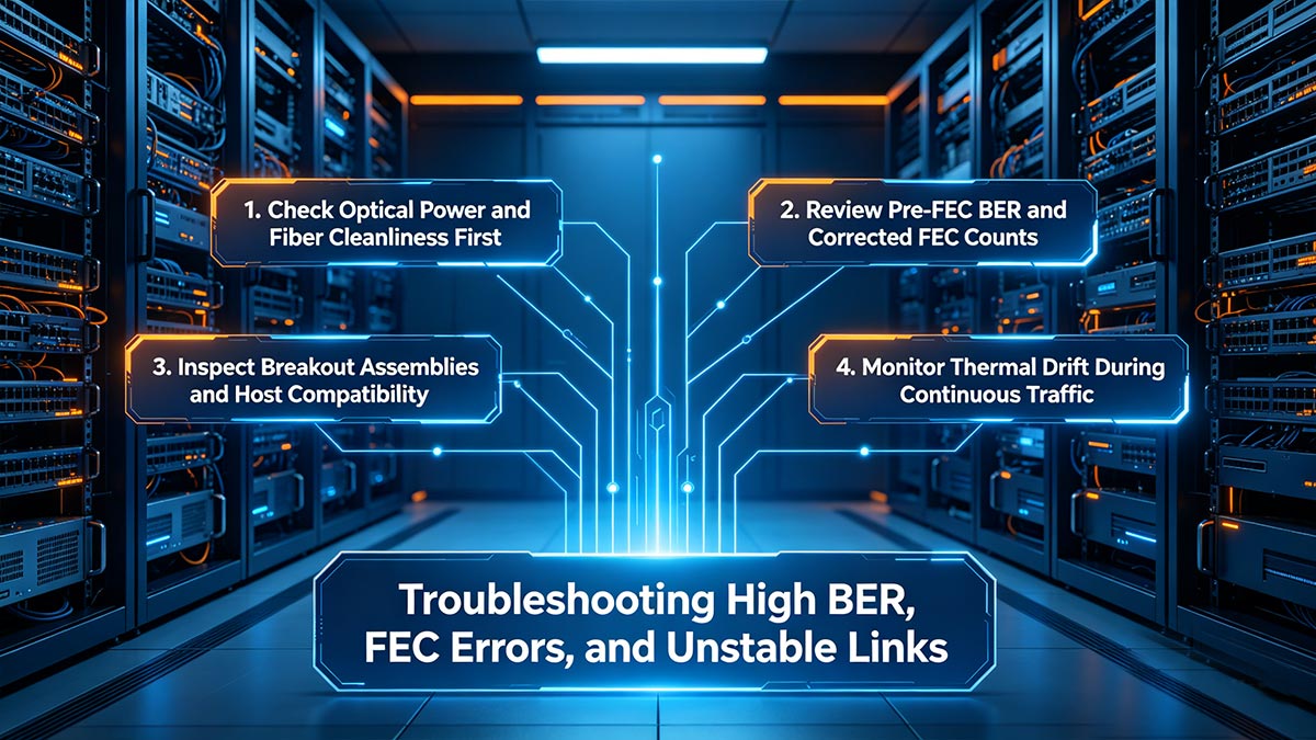
1. Check Optical Power and Fiber Cleanliness First
High BER is often caused by basic physical layer issues such as:
-
dirty MPO/MTP connectors,
-
excessive insertion loss,
-
fiber bend attenuation,
-
poor connector alignment.
Even slight optical imbalance across one or two lanes can increase corrected errors significantly in 400G PAM4 transmission.
For this reason, optical cleaning and power re-measurement should always be the first diagnostic step.
2. Review Pre-FEC BER and Corrected FEC Counts
If the link remains up but FEC counters continue rising, the module may be depending too heavily on error correction.
Engineers should verify:
-
whether pre-FEC BER is increasing,
-
whether one lane shows more corrected errors than others,
-
whether corrected counts rise faster under load.
This helps determine whether the issue is a temporary noise condition or a persistent physical layer weakness.
3. Inspect Breakout Assemblies and Host Compatibility
In 400G to 4×100G breakout deployments, unstable BER often comes from:
-
breakout cable insertion mismatch,
-
lane mapping inconsistency,
-
unsupported host firmware,
-
vendor interoperability differences.
A single unstable breakout lane can trigger repeated FEC corrections while the other channels appear normal.
That is why breakout assemblies should be tested separately during fault isolation.
4. Monitor Thermal Drift During Continuous Traffic
Some QSFP-DD modules only show BER fluctuation after extended line-rate operation.
Possible reasons include:
Running sustained traffic while observing BER and FEC trends can quickly show whether the instability is thermal-related rather than optical-loss related.
Common Root Causes Behind 400G Link Instability
Most unstable QSFP-DD 400G links can be traced back to one of these areas:
-
optical contamination or loss imbalance,
-
host-side electrical signal degradation,
-
breakout cable inconsistency,
-
thermal performance issues,
-
vendor interoperability mismatch.
By checking these factors in sequence, engineers can locate the failure source much faster than relying only on link alarms.
🚩 FAQ About QSFP-DD 400G Test Solutions
Q1. What is a QSFP-DD 400G test solution?
A QSFP-DD 400G test solution is a validation setup used to measure BER, FEC performance, optical power, and lane stability of a 400G QSFP-DD transceiver before deployment. It helps engineers verify whether the module can maintain reliable high-speed transmission under real network traffic conditions.
Q2. Why is BER monitoring important for QSFP-DD 400G modules?
BER monitoring shows how many transmission bits are received incorrectly across the 400G optical channel. Since QSFP-DD modules use 8 high-speed PAM4 lanes, even small signal degradation can create hidden bit errors. BER testing helps detect these problems before they cause packet loss or unstable throughput.
Q3. What causes high FEC correction counts in a 400G QSFP-DD link?
High FEC counts usually indicate that the link is correcting a growing number of physical layer errors. Common causes include dirty MPO connectors, fiber insertion loss, lane imbalance, thermal drift, or host-side signal degradation. Although the link may remain up, rising FEC corrections often mean the channel is losing stability margin.
Q4. How do engineers test QSFP-DD 400G breakout links?
For 400G QSFP-DD to 4×100G breakout testing, engineers check BER consistency, lane mapping, FEC behavior, and long-duration traffic stability across all breakout channels. Because each lane group operates independently, breakout validation is essential to ensure no individual 100G path develops hidden errors.
Q5. What is the difference between pre-FEC BER and post-FEC BER?
Pre-FEC BER measures raw bit errors before Forward Error Correction is applied, while post-FEC BER shows the remaining errors after correction. Pre-FEC BER is more useful for judging actual signal quality because it reveals whether the link is relying too heavily on FEC to stay operational.
Q6. Can a QSFP-DD 400G link pass traffic even with poor signal quality?
Yes. A 400G link can show normal link-up status and still operate with rising BER or heavy FEC correction in the background. This is why throughput tests alone are not enough. Engineers use BER monitoring and link quality validation to confirm whether the optical channel has enough margin for long-term production use.
Q7. What tools are commonly used in QSFP-DD 400G module testing?
Typical tools include BER testers, optical power meters, traffic generators, FEC monitoring software, and signal integrity analyzers. Together, these instruments help engineers evaluate optical performance, lane stability, and real traffic reliability in QSFP-DD 400G deployments.
Q8. How do I choose a reliable QSFP-DD 400G module for testing?
A reliable module should provide stable PAM4 transmission, low BER performance, strong FEC tolerance, accurate EEPROM compatibility, and consistent breakout interoperability. Using enterprise-grade transceivers from trusted suppliers such as the LINK-PP Official Store can significantly improve the accuracy of your validation results.
🚩 How to Choose the Right QSFP-DD 400G Test Setup
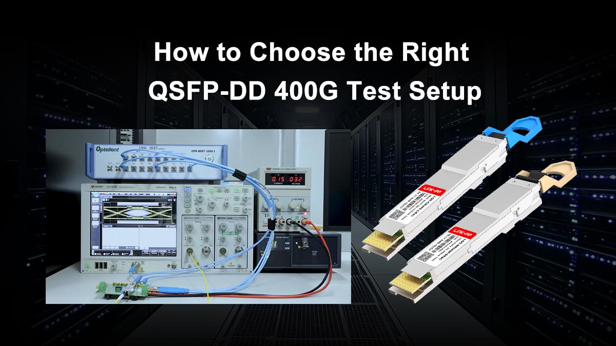
Selecting the right QSFP-DD 400G test setup depends on one simple goal: the test environment must be able to reveal hidden signal weakness before the module is placed into a live 400G network.
A practical validation system should not only confirm that the port links up, but also provide clear visibility into:
-
BER performance,
-
pre-FEC and post-FEC error behavior,
-
lane consistency,
-
optical power balance,
-
long-duration traffic stability,
-
and breakout interoperability.
In other words, the best test setup is one that can evaluate both immediate connectivity and long-term link margin.
Key Factors to Consider When Building a 400G Test Setup
Before choosing instruments or modules, engineers should focus on three critical questions:
1. Does the setup support accurate BER and FEC monitoring?
Without these two metrics, silent PAM4 degradation can easily go undetected.
2. Can it simulate real deployment scenarios?
A useful test solution should cover native 400G transmission, breakout testing, and sustained line-rate traffic.
3. Is the optical module itself built for stable validation?
Even the best tester cannot produce reliable results if the transceiver under test has weak thermal control, inconsistent lane calibration, or poor interoperability.
This is why both the testing platform and the quality of the QSFP-DD 400G optical module matter equally.
Why Reliable Module Selection Matters as Much as the Tester
Many 400G validation issues are not caused by the BER instrument itself, but by marginal transceiver performance:
-
unstable PAM4 eye quality,
-
excessive FEC dependence,
-
inconsistent EEPROM compatibility,
-
poor breakout behavior,
-
or thermal drift under continuous load.
Choosing enterprise-grade, standards-compliant modules makes the entire testing process more meaningful because engineers can evaluate the network—not compensate for unreliable optics.
For data centers, telecom backbones, AI clusters, and high-density switch fabrics, using verified 400G QSFP-DD transceivers with strong interoperability support greatly reduces deployment risk.
Final Thoughts
As 400G Ethernet adoption continues to expand, BER monitoring and link quality testing are no longer optional laboratory procedures—they are essential reliability checkpoints.
A well-designed QSFP-DD 400G test solution helps engineers detect silent signal degradation, control FEC-related risk, validate breakout performance, and ensure that every 400G channel can support long-term production traffic with confidence.
If you are planning to deploy, qualify, or troubleshoot 400G QSFP-DD optical modules, selecting high-quality transceivers is the first step toward obtaining meaningful and repeatable test results.
For professionally engineered QSFP-DD 400G modules, breakout solutions, and data-center-grade optical connectivity products, you can explore the LINK-PP Official Store for verified options designed for stable interoperability and high-speed network validation.