
As data centers and enterprise networks push for faster speeds, network engineers face a critical bottleneck: multimode distance limitations. When upgrading from 10G to 40G or 100G, standard fiber cables quickly hit their physical limits, leading to dropped packets and signal degradation if the cable runs are too long. Choosing the wrong infrastructure at this stage can stall an entire network migration.
This is where the debate between OM3 and OM4 fiber optics becomes vital. While both support high-speed data transmission, their maximum multimode distance capabilities differ significantly due to differences in modal bandwidth and signal attenuation. Understanding these limits is essential for optimizing your cable runs, managing your optical loss budget, and preventing costly connectivity failures.
📜 Core Technical Differences Influencing OM3 vs. OM4 Multimode Distance
The variations in maximum reach between OM3 and OM4 fiber are rooted deeply in their internal manufacturing standards and optical specifications. While both cables share the same 50-micron core size, their internal construction dictates how efficiently they carry high-speed data. Examining these core physical traits reveals exactly why one standard outperforms the other over longer spans.
Effective Modal Bandwidth (EMB) Ratings at 850nm
Effective Modal Bandwidth (EMB) is the primary metric that determines how much data a fiber can carry over a specific distance. Measured at the standard 850nm wavelength, EMB quantifies the fiber's ability to minimize signal distortion.
OM3 fiber delivers an EMB rating of 2000MHz·km, which is sufficient for many standard enterprise layouts. In contrast, OM4 fiber raises this benchmark to 4700MHz·km, offering more than double the bandwidth capacity. This massive increase in EMB is the main reason OM4 can sustain strong signals over much longer distances.
Modal Dispersion and Its Direct Impact on Light Propagation
Modal dispersion occurs when different light rays, or modes, travel down the fiber core at slightly different speeds and arrive at the receiver at different times. When these light pulses overlap, the data becomes blurry and unreadable for the network equipment.
To understand how this phenomenon directly degrades network performance, consider the following key impacts:
- Light pulses spread out as they travel further down the cable.
- Overlapping pulses cause severe intersymbol interference (ISI).
- Excessive pulse spreading forces a reduction in maximum allowable cable length.
- Higher data rates make the system much more sensitive to these timing delays.
Why OM4 Achieves Extended Reach Over Legacy OM3 Fibers
OM4 fiber features a highly refined, precision-engineered refractive index profile within its glass core compared to legacy OM3. This superior manufacturing control ensures that all light modes travel at nearly identical speeds, drastically reducing signal distortion.
Because the light paths remain perfectly synchronized, OM4 can maintain signal integrity across much longer physical distances. This allows network architects to deploy longer cable runs without worrying about immediate signal degradation or data loss.
VCSEL Transceiver Compatibility Across Both Standards
Both OM3 and OM4 fibers are fully optimized for use with Vertical-Cavity Surface-Emitting Laser (VCSEL) transceivers operating at 850nm. These low-cost, high-speed lasers are the standard choice for short-reach applications in modern data centers.
Fortunately, because both fiber types share identical physical geometry, they offer seamless backward and forward compatibility with standard VCSEL hardware. This means you can plug the same transceiver into either an OM3 or OM4 link without facing any hardware mismatch issues.
📜 10G Ethernet Standards and Maximum OM3 vs. OM4 Multimode Distance
Deploying 10G Ethernet requires a clear understanding of the reach limits defined by IEEE networking standards. While 10G is a mature technology, choosing between OM3 and OM4 fiber directly impacts how far signals can travel without data corruption. Mapping these standards ensures enterprise networks remain stable and cost-effective over long operational lifespans.
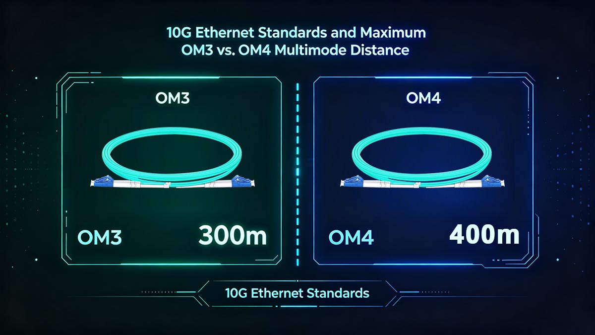
The 300-Meter Limit: 10GBASE-SR Specifications for OM3
The 10GBASE-SR standard is the baseline specification for 10-Gigabit Ethernet over multimode fiber using short-wavelength transceivers. Under this standard, OM3 fiber is officially rated to support a maximum multimode distance of 300m. This distance satisfies the layout requirements for most standard corporate server rooms and commercial building floors.
Pushing an OM3 cable beyond this 300-meter threshold risks high bit error rates due to the fiber's modal bandwidth limits. If your network design requires longer runs, relying on OM3 may result in intermittent connectivity issues or total link failure.
The 400-Meter Limit: Pushing 10G Links Further with OM4
OM4 fiber extends the capabilities of the 10GBASE-SR standard by pushing the maximum multimode distance to 400m. This extra 100 meters provides crucial flexibility for larger facilities and distributed network architectures. The extended reach is made possible by OM4's superior glass engineering, which keeps the light pulses tightly focused over longer spans.
This 400-meter reach allows engineers to deploy multimode fiber in scenarios that would otherwise require expensive single-mode optics. By utilizing OM4, organizations can maintain the lower cost-per-port benefits of multimode electronics while covering more physical ground.
Signal Attenuation and Link Power Budgets at 10Gbps
As light travels through a fiber optic cable, it naturally loses strength, a process known as signal attenuation. To ensure a successful 10G connection, the total power loss from the cable, connectors, and splices must stay within the transceiver's allowed link power budget. If the loss exceeds this budget, the receiving optic will not be able to decode the data clearly.
The following data compares the key attenuation values and power budget metrics that govern 10G links over both fiber types:
| Metric / Parameter |
OM3 Fiber (10GBASE-SR) |
OM4 Fiber (10GBASE-SR) |
| Maximum Standard Distance |
300m |
400m |
| Fiber Attenuation (at 850nm) |
≤ 3.0dB/km |
≤ 3.0dB/km |
| Total Channel Power Budget |
2.6dB |
2.9dB |
Choosing Between OM3 and OM4 for Campus Backbone Deployments
When designing a campus backbone network, choosing the right fiber standard is a balance between current costs and future migration paths. OM3 is often chosen for tighter budgets where link distances strictly fall under 300m. However, it leaves very little room for future upgrades if the campus expands or moves to higher data speeds.
Opting for OM4 in a campus backbone provides a safety margin for distance and ensures the physical cabling is ready for future upgrades. It safeguards your investment by allowing a smooth transition to 40G and 100G speeds down the road without forcing a complete cable re-pull.
📜 40G Network Migration: Mapping OM3 vs. OM4 Multimode Distance Capabilities
Upgrading data center speeds to 40G Ethernet introduces brand-new cabling methodologies and stricter transmission constraints. As data rates climb, the maximum achievable multimode distance drops significantly compared to older 10G networks. Mapping these capabilities ensures your migration path avoids unexpected signal loss and remains fully compliant with industry standards.
Parallel Optics and the Function of MPO/MTP Interfaces
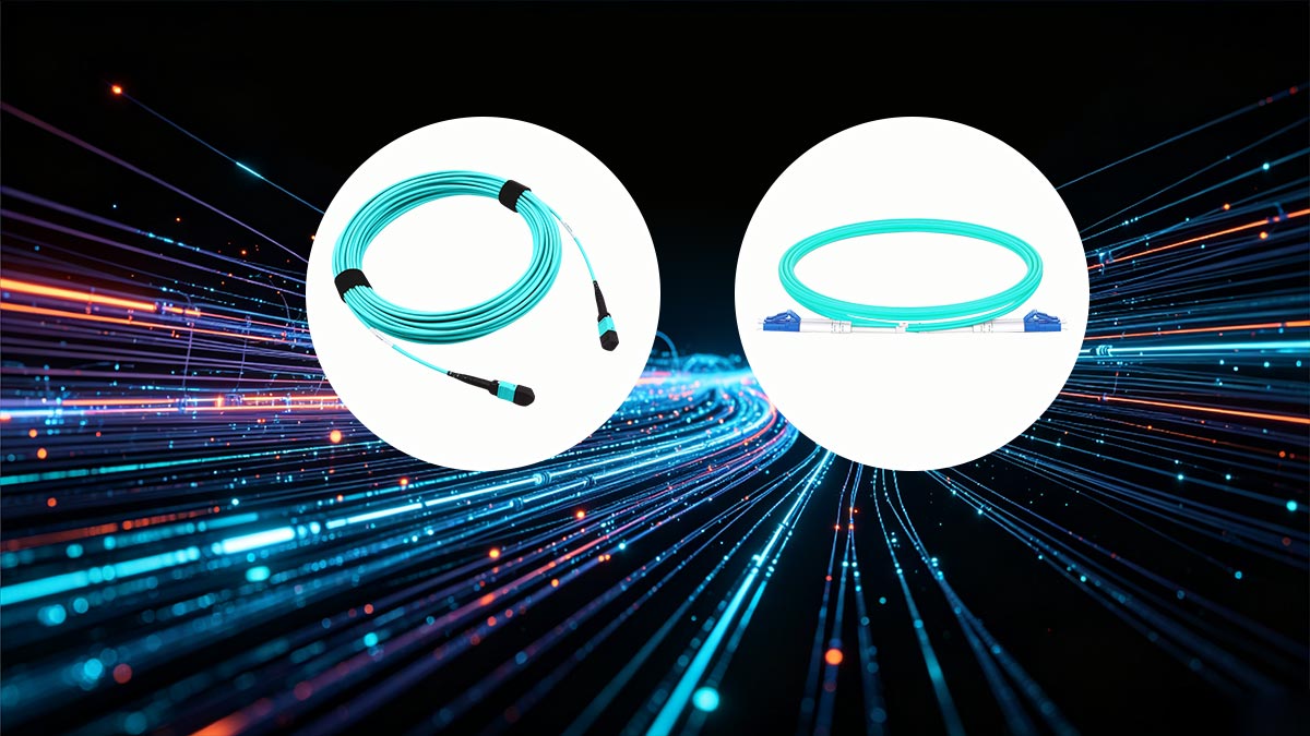
Unlike traditional 10G networks that rely on two-fiber LC connectors, standard 40G transmissions utilize parallel optics technology. This approach splits a single 40G data stream across multiple fiber strands simultaneously, utilizing multi-fiber MPO or MTP connectors. An MPO interface typically uses 8 or 12 fibers, with 4 strands dedicated to transmitting data and 4 strands dedicated to receiving data.
While this configuration vastly multiplies network throughput, it also requires tight synchronization between the strands. Precise cable alignment becomes vital to maintaining an acceptable multimode distance without data skew. If the fiber strands vary slightly in length or quality, the arriving signals become misaligned, limiting the effective reach of the setup.
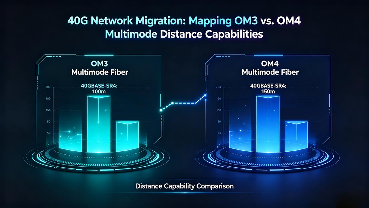
40GBASE-SR4 Distance Breakdown: 100 Meters vs. 150 Meters
The 40GBASE-SR4 standard defines the core requirements for running 40G traffic over multi-fiber parallel optics. Because of its lower modal bandwidth, OM3 fiber hits a strict maximum multimode distance limit of 100m under this specification. This 100-meter reach is often sufficient for standard, single-row server cabinet setups.
Upgrading to premium OM4 fiber expands this allowable boundary to 150m, giving network architects an extra 50-meter safety margin. This extended multimode distance is highly critical when designing structured cabling runs between different data center rows. By choosing OM4, you minimize the fiber dispersion penalty and ensure the transceiver can decode data accurately across a longer distance.
BiDi (Bi-Directional) Transceiver Performance on OM3 and OM4
For facilities hoping to keep their existing 10G LC patch cords, 40G BiDi (Bi-Directional) transceivers offer a clever alternative. Instead of using separate fibers, these optics aggregate four independent 10Gbps channels onto a single pair of strands. They transmit and receive simultaneously over two distinct wavelengths, specifically 850nm and 910nm, to prevent signal collision.
When it comes to multimode distance performance, BiDi optics are still heavily bound by the underlying glass quality. On OM3 fiber, a 40G BiDi link can reliably travel up to a maximum distance of 100m. Upgrading the underlying infrastructure to OM4 extends that identical BiDi link up to 150m, matching standard parallel optics limits.
Managing Insertion Loss in High-Density 40G Leaf-Spine Topologies
Modern high-density leaf-spine topologies require multiple patch panels and cross-connects to route data efficiently across the data center. Every single connection point introduces insertion loss, which drains power from the optical signal. If these losses pile up, they will prematurely shorten your maximum multimode distance.
To protect your 40G links, designers must use premium, low-loss MPO connectors throughout the leaf-spine layout. Carefully calculating the collective loss budget prevents your high-speed signals from degrading before they reach the destination switches. Managing this budget strictly is the only way to achieve the maximum specified multimode distance without errors.
📜 100G Data Center Deployment: OM3 vs. OM4 Multimode Distance Constraints
Deploying 100G Ethernet within modern data centers demands strict adherence to optical reach limitations. At such ultra-high data rates, the window for signal distortion shrinks significantly, making the choice of fiber infrastructure more critical than ever. Managing the maximum multimode distance at 100G becomes a primary factor in preventing packet loss and ensuring stable network performance.
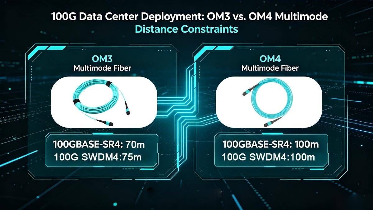
100GBASE-SR4 Standard: Comparing the 70m and 100m Reach Limits
The 100GBASE-SR4 standard utilizes parallel optics, transmitting data across four independent 25Gbps channels simultaneously via an MPO/MTP connector. Under this strict specification, OM3 fiber delivers a maximum multimode distance of only 70m. This compressed reach means that even slight variations in routing can push a cable run past its operational limit.
Upgrading to OM4 fiber extends this maximum multimode distance threshold to 100m. While an extra 30m might seem modest, it provides the vital headroom needed to span across multiple rows of server racks. This difference often determines whether a data center can use cost-effective multimode electronics or is forced to buy expensive single-mode alternatives.
100G SWDM4 Reach Advantages: Distances on OM3 vs. OM4
Short-wavelength Duplex Multiplexing (SWDM) technology offers an innovative way to achieve 100G speeds without necessarily moving to multi-fiber MPO assemblies. It multiplexes four 25Gbps wavelengths onto a single pair of standard duplex LC fibers, operating across a spectrum from 850nm to 940nm. This approach greatly simplifies high-density patch panel routing.
When utilizing 100G SWDM4 optics, the available multimode distance receives a notable boost over traditional parallel standards. On OM3 fiber, a 100G SWDM4 link can reliably stretch up to 75m. Moving to OM4 fiber pushes this multimode distance capability up to 100m, allowing organizations to maintain clean, two-fiber duplex cabling across longer spans.
Cable Run Planning for Top-of-Rack (ToR) vs. End-of-Row (EoR) Layouts
Choosing between OM3 and OM4 fiber heavily influences the underlying physical architecture of a data center floor. In a Top-of-Rack (ToR) layout, switches sit directly inside the same cabinet as the servers, keeping the required cable lengths very short. For these localized connections, the tight multimode distance limit of OM3 fiber rarely presents a problem.
However, End-of-Row (EoR) or Centralized Row architectures consolidate switches at the end of a long cabinet aisle. In these configurations, the overhead tray paths and vertical drops easily consume dozens of meters of cable. Because of these long paths, OM4 fiber is typically required to maintain an adequate multimode distance margin across the entire structured cabling run.
Assessing Signal Integrity at Ultra-High Bit Rates
Operating at 100Gbps leaves almost no room for timing errors or light scattering inside the fiber core. At these ultra-high bit rates, the receiver components are incredibly sensitive to any degradation in the incoming light pulses. If a cable run exceeds its rated multimode distance, the pulses distort rapidly, leading to immediate data corruption.
To maintain perfect signal integrity, network designs must account for both chromatic dispersion and modal noise. Using OM4 fiber helps stabilize the signal because its superior glass structure minimizes the distortion that naturally builds up over longer runs. This ensures that the high-frequency light pulses arrive cleanly, keeping the network error-free at maximum multimode distance.
📜 Managing the Optical Insertion Loss Budget to Protect Multimode Distance
Calculating and managing optical insertion loss is just as vital as tracking the physical length of your fiber runs. Every connector, splice, and patch panel interface absorbs and scatters a small amount of light energy, fading the signal. If these combined losses breach your strict engineering limits, your network will fail to reach its maximum specified multimode distance.
Maximum Allowed dB Loss Limits for OM3 and OM4 Channels
Industry standards establish a hard ceiling for the amount of decibel (dB) loss a fiber channel can tolerate before data stops flowing. This loss budget is highly dependent on your target data rate, shrinking significantly as network speeds increase. Keeping your total link loss below these limits is the only way to ensure reliable data delivery across the target multimode distance.
To secure proper channel performance, you must adhere to these maximum standard loss limits:
- 10G networks allow a maximum channel loss of 2.9dB.
- 40G parallel networks require a total channel loss to stay under 1.5dB.
- 100G networks compress the allowed channel budget down to 1.5dB or less.
- Exceeding these values causes immediate packet dropping at maximum multimode distance.
How Connector Penalties (MPO vs. LC) Degrade Maximum Reach
The physical style of your fiber connectors introduces unique loss penalties that directly steal power from the optical transmitter. Traditional duplex LC connectors are easy to align perfectly, but high-density MPO or MTP connectors feature multiple fiber pins that are much harder to match precisely. These slight mechanical variations create instant light reflections and attenuation.
The specific connector types you deploy impact your link performance through the following factors:
- Standard LC connectors typically introduce a 0.5dB loss per pair.
- Low-loss premium LC components drop that penalty down to 0.15dB.
- Standard MPO multi-fiber connectors often suffer a higher 0.75dB loss.
- High connector penalties shorten your achievable multimode distance by draining the power budget early.
The Hidden Impact of Splices and Patch Panels on Total Distance
Structured cabling designs in modern data centers frequently route light through multiple patch panels and fusion splices to keep layouts organized. While these routing points make day-to-day management easy, they act as hidden blockades for light propagation. Each mid-span connection point adds a cumulative loss penalty that steadily eats away at your signal strength.
Every extra patch or splice in the line harms your network through these distinct avenues:
- Fusion splices add a typical attenuation penalty of 0.1dB to 0.3dB.
- Mechanical splices create a higher loss, usually around 0.3dB per point.
- Multi-stage patch panels create a compound loss effect across the facility.
- Too many intermediate connections will drastically decrease your maximum stable multimode distance.
Step-by-Step Channel Loss Calculation for Fiber Budgeting
Before pulling any fiber through your building, you must perform a formal channel loss calculation to guarantee the link will work. This mathematical calculation sums up the worst-case losses of your cable attenuation, connectors, and splices. Comparing this total number against the transceiver specification ensures your design supports the desired multimode distance.
The essential calculation process involves tracking these specific components in order:
- Multiply the total cable length by the fiber's attenuation rate per kilometer.
- Count the total number of mating connector pairs and multiply by their rated loss.
- Add the individual loss values of all planned splices along the run.
- Include a small safety margin, typically 0.3dB, to account for component aging.
- Verify the grand total stays below the transceiver's maximum allowed budget.
📜 Troubleshooting Signal Degradation and Multimode Distance Failures
When high-speed fiber links experience intermittent drops or poor performance, pinpointing the root cause requires a systematic diagnostic approach. Networks running near their physical limits are highly vulnerable to slight drops in optical power and timing errors. Isolating these issues quickly ensures your fiber runs stay operational and completely stable across the required multimode distance.
Identifying Bit Error Rate (BER) Spikes Caused by Over-Length Links
A Bit Error Rate (BER) spike is the primary symptom of a fiber link that has been pushed past its maximum length limits. As light pulses spread out over a long run, the receiver struggles to distinguish between data bits, resulting in corrupted packets. Monitoring these error trends helps engineers identify physical infrastructure bottlenecks before a total link failure occurs.
Excessive cable lengths reveal themselves through the following network performance indicators:
- Frame Check Sequence (FCS) errors rise sharply on switch ports.
- Packet retransmissions increase and cause visible network latency.
- Link flapping occurs as the switches struggle to maintain a steady handshake.
- Network throughput drops significantly below the rated bandwidth limit.
- Signal degradation worsens during periods of high data traffic.
Using OTDR (Optical Time-Domain Reflectometer) to Verify Fiber Length
An Optical Time-Domain Reflectometer (OTDR) is an essential diagnostic tool used to map the physical characteristics of a fiber run. By sending high-power light pulses down the core and measuring the reflections, it creates a visual trace of the entire channel. This tool allows technicians to verify if a cable path accidentally violates the recommended multimode distance.
Using an OTDR provides critical visibility into your fiber plant by exposing these key details:
- The exact physical length of the entire fiber run is measured accurately.
- High-loss connection points are mapped out with pinpoint precision.
- Micro-bends and macro-bends are easily located inside cable trays.
- Severe reflection points from bad connectors are identified immediately.
- Real-time distance measurements can be compared directly to standard specifications.
Distinguishing Between Distance Limitations and Dirty Optical Faces
Technicians often confuse the symptoms of an over-length cable run with the signal loss caused by contaminated connector end-faces. A single speck of dust or oil on a fiber ferrule can block the light path and mimic the attenuation of an over-length link. Distinguishing between these two issues prevents engineers from replacing perfectly good cables.
To accurately separate a contamination issue from a physical length limitation, use the following troubleshooting steps:
- Inspect all connector end-faces using a specialized fiber microscope.
- Look for dry dust, oil smudges, or scratches on the glass core.
- Clean dirty connectors using click-cleaners or lint-free wipes.
- Re-test the link power levels immediately after performing the cleaning.
- Identify a permanent distance issue if the signal remains weak after thorough cleaning.
Monitoring Transceiver Power Levels via Digital Diagnostic Monitoring (DDM)
Digital Diagnostic Monitoring (DDM) is a built-in technology found in modern SFP and QSFP transceivers. It provides real-time access to critical operating parameters, including laser transmit power, received optical power, and temperature. Checking these metrics allows operators to instantly see if an optical signal is strong enough to survive the multimode distance.
Regularly checking DDM values keeps your high-speed links safe by highlighting these vital metrics:
- Transmit (Tx) power levels show if the laser is degrading over time.
- Receive (Rx) power levels indicate if too much light is lost in transit.
- Low Rx power warnings flag links that are dangerously close to failing.
- Real-time voltage readouts help identify unstable power supplies.
- Sudden drops in Rx power alert teams to recent physical cable damage.
📜 Sourcing Standards-Compliant Hardware for Optimized Multimode Distance
Achieving the maximum performance from your fiber infrastructure depends heavily on the quality of the physical components you purchase. Substandard patch cords or uncertified optical transceivers can introduce severe signal attenuation and timing delays right out of the box. Investing in verified, standards-compliant hardware is an important step to help safeguard your network stability across the entire specified multimode distance.
Selecting Certified Premium OM3 and OM4 Fiber Patch Cords
When purchasing patch cords, look for products that explicitly state compliance with TIA/EIA and ISO/IEC international standards. Lower-grade bargain cables sometimes cut corners on glass purity, leading to localized imperfections that distort the light pulses. These subtle defects can cause sudden drop-offs in signal strength before the connection can span its full multimode distance.
It is worth noting that while some premium patch cords utilize specialized bend-insensitive multimode fiber (BIMMF) to maintain low loss around tight corners, this is not a default feature of all standard-compliant cables. Standard OM3 and OM4 fibers remain sensitive to tight macro-bends, meaning careful routing remains necessary unless bend-insensitive variants are explicitly selected. Choosing components certified by trusted testing bodies ensures that your runs match their rated bandwidth values under proper installation conditions.
The Importance of Low-Loss Connectors for Maximum Reach Stability
Connectors are vulnerable points in any fiber optic link because they introduce physical gaps where light can scatter. Standard-grade connectors often bring a higher insertion loss penalty that rapidly drains your overall channel power allowance. Opting for factory-terminated, low-loss connectors can be crucial to keeping the link stable over its maximum multimode distance.
Low-loss MPO and LC connectors feature ultra-precise ceramic ferrules designed to align the delicate glass cores with microscopic accuracy. By reducing reflection and light scatter at every junction, these premium components preserve valuable optical energy. This extra power margin provides a helpful safety net that allows your signals to travel the maximum multimode distance with a lower risk of error.
Ensuring Transceiver-to-Fiber Interoperability for Maximum Reach Stability
A high-speed optical link relies on a complex interaction between the laser transceiver and the underlying glass infrastructure. If the optical launch characteristics of the transceiver do not align well with the core properties of your OM3 or OM4 cabling, signal quality will degrade prematurely. Ensuring proper interoperability across all active and passive components helps prevent unexpected dropouts as you approach the maximum limits of your multimode distance.
To achieve a stable link, engineers should focus on sourcing transceivers that strictly adhere to IEEE and multi-source agreement (MSA) standards. Mismatches in laser specifications can lead to erratic light propagation, increased bit error rates, and unstable link operation over longer runs. Choosing fully compatible, high-quality optics ensures clean light delivery, allowing the system to maintain optimal performance along every meter of the designated multimode distance.
Ensuring Quality Assurance with Vendor Test Reports
Reliable hardware manufacturers typically provide serialized, individual test reports for every fiber assembly they ship. These documents show verified laboratory measurements for insertion loss and return loss taken directly on the factory floor. Reviewing these reports gives deployment teams solid proof that the cables are capable of supporting the intended multimode distance.
Relying solely on generic bulk guarantees that claim a batch of cables is simply "good enough" for enterprise use can introduce unnecessary risks. If a vendor cannot supply specific test data for a multi-fiber bundle or patch cord, the potential for deployment issues increases. Demanding transparent factory test reports is an excellent practice to help prevent hidden infrastructure flaws from limiting your network's multimode distance.
📜 Key Takeaways on OM3 vs. OM4 Multimode Distance Limits and Performance
Navigating the choices between OM3 and OM4 cabling comes down to balancing your current reach requirements with future network upgrade paths. While OM3 fiber remains a highly cost-effective option for shorter spans, upgrading to OM4 provides a significant boost in multimode distance capabilities at higher data rates like 40G and 100G. Keeping a strict eye on your insertion loss budgets and choosing standards-compliant hardware are the best ways to keep your high-speed links reliable and completely error-free.
Ready to optimize your fiber infrastructure and secure maximum reach stability across your entire data center floor? Visit the LINK-PP Official Store to browse a premium selection of high-performance optical transceivers engineered to deliver flawless interoperability and maximize your multimode distance.


