
As data center networks evolve toward higher bandwidth density, the 400G-SR8 transceiver has become one of the most important short-reach optical solutions for high-performance interconnects. Built on a 16-fiber parallel architecture, SR8 represents a key step in scaling 400G connectivity within multimode fiber environments, especially where low latency and high port density are required.
Unlike serial or wavelength-multiplexed optics, the 400G-SR8 design uses eight electrical lanes converted into parallel optical transmission paths, typically delivered through an MPO/MTP-16 connector system. This enables simultaneous data transmission across multiple fiber pairs, making it highly suitable for intra-data center links such as leaf-to-spine switches, AI clusters, and high-density computing fabrics.
However, SR8 is not just about speed—it is about architectural tradeoffs. Its performance is tightly coupled with multimode fiber infrastructure (typically OM4/OM5), short-reach distance constraints, and precise cabling polarity requirements. These factors make it a highly efficient yet specialized solution in modern Ethernet evolution.
In this knowledge center guide, we will break down the 16-fiber parallel architecture behind 400G-SR8, explain how it works at a system level, compare it with other 400G optical modules, and clarify where it fits in next-generation network design. The goal is to give engineers and network architects a clear, technically accurate foundation for understanding SR8 in real-world deployments.
🔄 What Is a 400G-SR8 Transceiver?
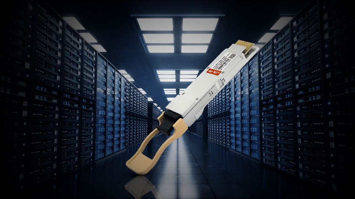
A 400G-SR8 transceiver is a short-reach optical module designed to transmit 400 Gigabit Ethernet over multimode fiber using a 16-fiber parallel interface (MPO/MTP-16). In simple terms, it is a high-speed data center optic that moves large volumes of data across very short distances—typically within the same rack or between nearby switches.
The “SR8” stands for Short Reach with 8 optical lanes, where each lane carries a portion of the total 400G bandwidth in parallel. This architecture enables extremely high throughput while keeping latency low, making it ideal for modern high-density computing environments.
This type of transceiver is primarily used in hyperscale data centers, cloud infrastructure, and AI/ML computing clusters, where large-scale switch-to-switch connectivity is required. It is especially common in leaf-spine network architectures, where hundreds or thousands of short optical links must operate efficiently and reliably.
Unlike long-reach or single-mode solutions, the 400G-SR8 is optimized for cost-effective, short-distance connectivity over multimode fiber (typically OM4 or OM5). Its design focuses on maximizing port density and bandwidth inside controlled data center environments rather than spanning long geographic distances.
🔄 How 400G-SR8 Works (Architecture Overview)
The 400G-SR8 transceiver operates using a parallel optical architecture, where high-speed electrical signals are converted into multiple synchronized optical lanes. Instead of transmitting data on a single high-speed channel, SR8 distributes traffic across 8 parallel optical paths, enabling efficient 400G transmission over short-reach multimode fiber links.
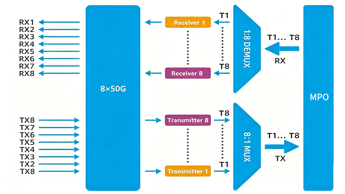
8×50G Electrical Lanes → Optical Conversion
At the host interface, the transceiver receives 8 electrical lanes running at approximately 50Gbps each. These electrical signals are processed by the module’s DSP/driver circuitry and then converted into optical signals.
- 8 lanes × 50G = 400G total bandwidth
- Each lane operates independently but is tightly synchronized
- This structure reduces signal complexity compared to higher-speed serial lanes
Key idea: SR8 achieves 400G not by increasing single-lane speed, but by scaling lanes in parallel.
Parallel Multimode Transmission
Once converted, the optical signals are transmitted simultaneously across eight parallel fiber pairs.
- Each lane travels over its own dedicated fiber path
- All lanes are transmitted at the same time (parallel transmission)
- This ensures low latency and high aggregate bandwidth
This is the defining feature of SR8: true parallel optics instead of serial aggregation.
MPO/MTP-16 Fiber Interface
The physical interface of 400G-SR8 uses a MPO/MTP-16 connector system, which supports:
- 16 fiber strands (8 transmit + 8 receive paths in a full-duplex configuration)
- Precise fiber alignment for parallel transmission
- High-density cabling in data center environments
This connector is essential for maintaining lane synchronization and minimizing optical skew between channels.
OM4 Fiber Dependency
400G-SR8 is designed specifically for multimode fiber infrastructure, typically:
- OM4 (standard deployment)
- OM5 (optimized wavelength flexibility in some cases)
Key characteristics:
- Reach is typically up to ~100 meters on OM4
- Performance depends heavily on fiber quality and polarity accuracy
- Used mainly in intra-data center environments
Diagram-Friendly Architecture Summary
You can visualize the SR8 architecture in four layers:
[Host Side]
8 × 50G Electrical Lanes
⬇
[Module DSP Layer]
Electrical → Optical Conversion
⬇
[Optical Layer]
8 Parallel Optical Channels
⬇
[Fiber Interface]
MPO/MTP-16 → OM4 Multimode Fiber
⬇
[Network Side]
Switch-to-switch / Leaf-spine short-reach links
Key Takeaway: The 400G-SR8 architecture is fundamentally a parallelized system, designed to maximize short-distance bandwidth efficiency. By combining 8×50G lanes, MPO/MTP-16 connectivity, and OM4 multimode fiber, it delivers high-density 400G connectivity optimized for modern data center fabrics.
🔄 Key Technical Specifications of 400G-SR8 Transceiver
The 400G-SR8 transceiver is defined by a set of standardized short-reach multimode optical parameters designed for high-density data center interconnects. These specifications reflect its role as a parallel 16-fiber architecture solution optimized for intra-data center networking, rather than long-haul transmission.
Core Technical Specifications
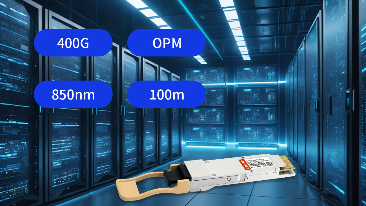
- Transmission Rate: 400G (8 × 50G electrical/optical lanes)
- Reach: ~70–100 meters (on OM4 multimode fiber, typical deployment)
- Wavelength: 850 nm (VCSEL-based transmission)
- Connector Type: MPO/MTP-16 parallel fiber interface
- Fiber Type: Multimode fiber (OM3 / OM4 / OM5 supported depending on design)
These parameters make SR8 particularly suitable for short-reach, high-bandwidth environments, where density and parallel throughput are prioritized over distance.
400G-SR8 Technical Specifications Table
| Parameter |
Specification |
| Transmission Rate |
400G Ethernet |
| Electrical Lanes |
8 × 50G |
| Optical Lanes |
8 parallel lanes |
| Wavelength |
850 nm VCSEL |
| Reach (Typical) |
70–100 m (OM4 fiber) |
| Fiber Type |
Multimode (OM3 / OM4 / OM5) |
| Connector |
MPO/MTP-16 |
| Transmission Mode |
Parallel optics |
| Application Scope |
Short-reach intra-data center links |
Key Insight: From a system design perspective, the 400G-SR8 specification set is optimized for bandwidth density rather than distance scaling. Its reliance on 850nm VCSEL technology and MPO/MTP-16 parallel fiber architecture reflects a deliberate engineering tradeoff: maximizing throughput per rack unit while operating within controlled multimode fiber environments.
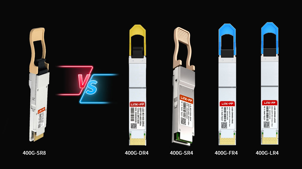
🔄 400G-SR8 vs. 400G DR4, SR4, and Other 400G Optics
When evaluating 400G optical transceivers, the key decision is not only speed, but also fiber type, reach, cabling complexity, and total deployment cost. The 400G-SR8 sits in the multimode short-reach segment, but it competes directly with several other 400G standards—especially DR4 and SR4.
This section breaks down how these optics differ in real data center design scenarios.
400G-SR8 vs. 400G DR4 (Multimode vs. Single-Mode Tradeoff)
400G DR4 uses single-mode fiber (SMF) and typically provides longer reach (up to ~500m or more depending on implementation), while 400G-SR8 is limited to short-reach multimode links (~100m).
Key differences:
- Fiber Type
- SR8: Multimode (OM4/OM5)
- DR4: Single-mode (OS2)
- Architecture
- SR8: 8× parallel lanes (MPO-16)
- DR4: 4×100G lanes (often MPO-12)
- Use Case
- SR8: Short intra-rack / row-to-row links
- DR4: Cross-row, campus-scale, or longer intra-DC links
Insight: DR4 is preferred when fiber scalability matters; SR8 is preferred when existing multimode infrastructure is already deployed.
400G-SR8 vs. 400G SR4 (Parallel Density vs Simplicity)
400G SR4 is another multimode solution but uses fewer fiber lanes (4×100G instead of 8×50G).
- SR8
- Higher lane count (8 lanes)
- More complex MPO-16 cabling
- Better alignment with some legacy breakout designs
- SR4
- Lower lane count (4 lanes)
- Simpler MPO-12 cabling
- Often more cost-efficient in newer deployments
Insight: SR8 favors parallel density; SR4 favors simplified fiber management.
400G-SR8 vs. Other 400G Optics (FR4 / LR4 Overview)
- FR4: Uses wavelength multiplexing over single-mode fiber, optimized for medium reach (~2 km range in many implementations)
- LR4: Designed for long-reach transmission (data center interconnect or metro links)
Compared to these:
- SR8 = shortest reach, highest multimode density
- FR4 = balanced reach + SMF efficiency
- LR4 = long-haul capability
Cost vs. Infrastructure Tradeoff
| Factor |
SR8 |
DR4 |
SR4 |
| Fiber Type |
Multimode |
Single-mode |
Multimode |
| Reach |
~100m |
~500m+ |
~70–100m |
| Cabling Complexity |
High (MPO-16) |
Medium |
Lower |
| Fiber Infrastructure Cost |
Lower (if MMF exists) |
Higher (SMF buildout) |
Lower–Medium |
| Port Density Efficiency |
High |
High |
High |
| Best Fit Scenario |
Existing MMF data centers |
Scalable new builds |
Simplified MMF designs |
Deployment Scenario Summary
- Use 400G-SR8 when:
- Multimode fiber infrastructure already exists
- Links are short-range (same row / adjacent racks)
- High parallel density is required
- Use 400G DR4 when:
- Long-term scalability is required
- Single-mode fiber is standard in the facility
- Distance flexibility is important
- Use 400G SR4 when:
- Simpler fiber management is preferred
- MPO-12 infrastructure is standardized
Key Takeaway: The decision between SR8, DR4, and SR4 is fundamentally an infrastructure strategy decision, not just a speed comparison. SR8 excels in high-density multimode environments, while DR4 dominates in future-proof single-mode architectures.
🔄 400G-SR8 in Data Center Network Design
The 400G-SR8 transceiver plays a critical role in modern high-density data center architectures, especially where short-reach, high-bandwidth connectivity is required. Its 16-fiber parallel design makes it particularly suitable for environments that prioritize port density, low latency, and scalable switching fabrics.
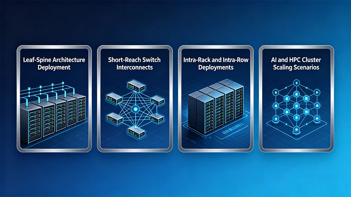
1. Leaf-Spine Architecture Deployment
In a typical leaf-spine topology, 400G-SR8 is widely used for high-speed inter-switch connections between leaf and spine layers.
- Leaf switches aggregate server traffic
- Spine switches provide non-blocking fabric interconnect
- SR8 enables multiple 400G links across short distances
Because these links are usually within the same data hall, SR8’s ~100m multimode reach is sufficient while offering high throughput per connection.
Key benefit: Efficient scaling of east-west traffic inside hyperscale fabrics.
2. Short-Reach Switch Interconnects
400G-SR8 is optimized for switch-to-switch connections within close proximity, such as:
- Top-of-rack (ToR) to aggregation switches
- Spine-to-spine interlinks in compact clusters
- Modular switch chassis interconnections
Its parallel optical lanes allow consistent low-latency transmission across multiple fiber pairs, making it ideal for bandwidth-intensive switching environments.
3. Intra-Rack and Intra-Row Deployments
One of the most common SR8 use cases is intra-rack or intra-row connectivity, where devices are physically close together.
Typical scenarios include:
- Server-to-switch connections within the same rack row
- High-speed GPU cluster interconnects
- Storage array connectivity inside adjacent racks
In these environments, SR8 provides a high-bandwidth, short-distance optical fabric without requiring single-mode fiber infrastructure.
4. AI and HPC Cluster Scaling Scenarios
The rapid growth of AI training workloads and HPC (High-Performance Computing) clusters has significantly increased demand for high-density 400G links.
400G-SR8 is commonly used in:
- GPU-to-GPU switching fabrics
- AI training cluster interconnects
- Distributed computing nodes requiring massive parallel throughput
Why SR8 fits AI/HPC workloads:
- High port density for scale-out GPU clusters
- Parallel architecture aligns with distributed compute patterns
- Low latency for synchronized workloads
- Efficient short-reach bandwidth aggregation
Key insight: SR8 is not just a networking component—it becomes part of the compute fabric architecture in AI-driven data centers.
Key Takeaway: In modern data center design, the 400G-SR8 transceiver is primarily a short-reach fabric enabler, optimized for leaf-spine scalability, intra-rack interconnects, and AI/HPC cluster expansion. Its parallel multimode architecture makes it a natural fit for environments where bandwidth density and physical proximity matter more than transmission distance.
🔄 400G-SR8 Module Compatibility and Deployment Requirements
Although the 400G-SR8 transceiver offers high bandwidth and efficient parallel transmission, its deployment is tightly dependent on hardware compatibility and physical layer conditions. Unlike simpler serial optics, SR8 requires careful planning across ports, fiber infrastructure, and vendor ecosystems.
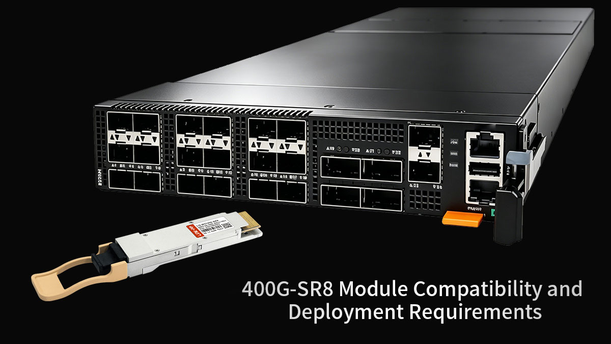
QSFP-DD Port Support Requirements
Most 400G-SR8 modules are built on the QSFP-DD (Quad Small Form-factor Pluggable Double Density) interface.
Key requirements include:
- Host switch must support QSFP-DD 400G SR8 optics
- Electrical interface must support 8×50G PAM4 lanes
- Backward compatibility is generally not guaranteed with QSFP28/QSFP56 cages
Important: Even if the form factor fits, electrical lane mapping must match SR8 architecture.
MPO Polarity and Fiber Mapping Considerations
Because SR8 uses a 16-fiber MPO/MTP-16 interface, polarity design is critical.
Key points:
- Correct Tx/Rx lane mapping is required for all 8 parallel channels
- MPO polarity type (A, B, or C) must match switch design
- Misalignment can cause partial or full link failure
- Cleaning and connector inspection are essential due to high fiber density
Insight: SR8 deployments are more sensitive to physical fiber handling than single-mode optics.
OM4 / OM5 Cabling Conditions
400G-SR8 is designed for multimode fiber environments, typically:
- OM4 fiber: standard for up to ~100m reach
- OM5 fiber: optional support for improved wavelength flexibility
Deployment constraints include:
- Distance is highly dependent on fiber quality and loss budget
- Bends, connectors, and patch panels significantly affect signal integrity
- Mixed OM3/OM4 environments may reduce effective reach
Key point: SR8 performance is infrastructure-dependent, not just module-dependent.
Switch Firmware and Vendor Coding Constraints
400G-SR8 modules often require strict vendor and firmware compatibility validation.
Common constraints:
- Vendor-coded optics may be required for full functionality
- Switch OS firmware must support 400G SR8 lane mapping
- Some platforms enforce transceiver authentication or EEPROM validation
- Firmware mismatches may lead to link down or reduced lane utilization
Insight: SR8 is not purely plug-and-play in heterogeneous environments.
Port Density and Network Planning Considerations
Because SR8 uses 8 lanes per port and MPO-16 cabling, it introduces planning challenges:
- High fiber density increases cable management complexity
- Patch panel space must accommodate MPO trunking systems
- Breakout designs can quickly consume physical port resources
- Airflow and cable routing become critical in high-density racks
At scale, network architects must balance:
- Port density vs fiber manageability
- Parallel architecture vs operational simplicity
- Expansion flexibility vs cabling overhead
Key Takeaway: The 400G-SR8 transceiver is highly efficient but infrastructure-sensitive. Successful deployment depends on:
- Proper QSFP-DD host support
- Accurate MPO polarity design
- Stable OM4/OM5 multimode fiber infrastructure
- Vendor-compatible firmware ecosystems
- Careful port density and cabling planning
In practice, SR8 delivers maximum value when optical, electrical, and physical layers are designed as a unified system rather than independently configured components.
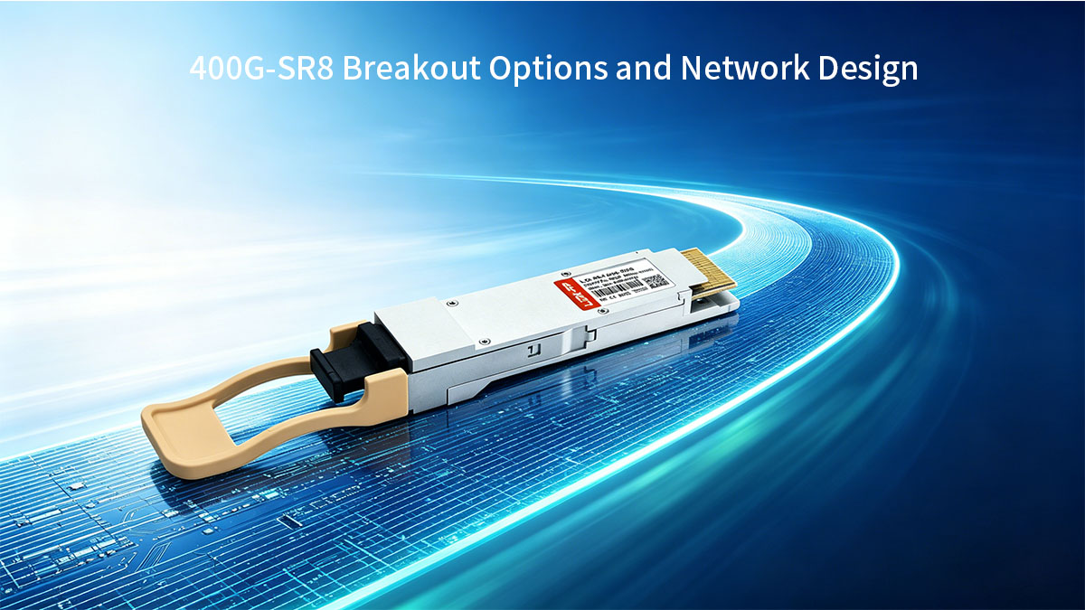
🔄 400G-SR8 Breakout Options and Network Design
One of the most important architectural advantages of the 400G-SR8 transceiver is its ability to support flexible breakout configurations, allowing a single 400G port to be divided into multiple lower-speed links. This capability is widely used in data center scaling strategies where gradual migration from 100G or 200G to 400G is required.
However, breakout design is not just a feature—it is a network planning decision that directly affects fiber usage, switch port efficiency, and operational complexity.
2×200G Breakout Scenario
In a 2×200G breakout configuration, the 400G-SR8 link is split into two independent 200G channels.
- Each 200G channel uses multiple SR8 lanes grouped together
- Typically applied in high-performance leaf-spine fabrics
- Enables smooth migration from 200G to 400G infrastructure
Where it is used:
- GPU clusters requiring large but not full 400G bandwidth per node
- Spine-to-leaf aggregation where 200G endpoints still exist
- Transitional network upgrades in staged deployments
Key benefit: Reduces disruption when upgrading partially from 200G to 400G.
8×50G Breakout Scenario
The most granular breakout mode is 8×50G, where the full 400G port is divided into eight independent 50G links.
- Each lane from the SR8 architecture maps to a separate 50G connection
- Requires precise MPO/MTP-16 lane breakout mapping
- Highly dependent on switch and cable infrastructure support
Where it is used:
- High-density server connectivity
- Top-of-rack switching environments
- Aggregation of multiple low-speed endpoints into a single 400G uplink
Key benefit: Maximizes port utilization in environments with mixed-speed devices.
When Breakout Design Is Practical
Breakout configurations are most effective when:
- Mixed-speed environments still exist (50G / 100G / 200G)
- Network migration is happening in phases
- High port utilization efficiency is required
- Switch platforms natively support SR8 lane splitting
Typical environments:
- Hyperscale data centers
- AI training clusters with heterogeneous nodes
- Gradual infrastructure upgrades
When Breakout Is NOT Ideal
Despite its flexibility, breakout is not always the optimal design choice.
Avoid or limit breakout when:
- Fully standardized 400G infrastructure is already deployed
- Fiber management complexity must be minimized
- MPO cabling overhead becomes operationally expensive
- Switch firmware does not fully support lane-level mapping
In these cases, native 400G point-to-point links are simpler and more stable.
Key Design Insight
The 400G-SR8 breakout model is fundamentally a migration and optimization tool, not just a connectivity feature. It allows network architects to:
- Extend the lifecycle of existing 50G/100G infrastructure
- Increase utilization efficiency of high-density switches
- Gradually transition toward full 400G fabrics
However, as network maturity increases, breakout usage typically decreases in favor of simpler, native high-speed 400G interconnects.
🔄 Common Questions About 400G-SR8 Transceivers
1. What is the reach of 400G-SR8?
The 400G-SR8 transceiver typically supports a reach of around 70 to 100 meters, depending on the quality of multimode fiber used.
- OM4 fiber: up to ~100 meters (most common case)
- OM3 fiber: shorter reach due to higher loss
- Performance depends heavily on cable quality and connector cleanliness
In practice, SR8 is designed strictly for intra-data center, short-reach links, not campus or metro distances.
2. Is 400G-SR8 multimode or single-mode?
The 400G-SR8 is a multimode optical transceiver.
- Uses 850nm VCSEL laser technology
- Designed for OM3/OM4/OM5 multimode fiber
- Not compatible with single-mode fiber (SMF) systems
This makes SR8 ideal for high-density short-reach data center environments, but unsuitable for long-distance transmission.
3. Can 400G-SR8 break out to lower speeds?
Yes, the 400G-SR8 supports breakout configurations, depending on switch and platform support.
Common breakout modes include:
- 2×200G breakout for partial aggregation use cases
- 8×50G breakout for high-density server connectivity
Breakout functionality requires:
- Proper lane mapping support in the switch
- Compatible MPO/MTP-16 cabling infrastructure
- Firmware support for SR8 lane division
4. Is 400G-SR8 compatible with QSFP-DD ports?
Yes, 400G-SR8 modules are designed for QSFP-DD form factor ports.
However, compatibility depends on multiple factors:
- Host switch must support QSFP-DD 400G SR8 optics
- Electrical interface must support 8×50G PAM4 lanes
- Vendor coding or firmware validation may be required
Important: Physical fit does not guarantee electrical or protocol compatibility.
5. When should I choose SR8 instead of DR4?
The choice between SR8 and DR4 depends mainly on fiber infrastructure and distance requirements.
Choose 400G-SR8 when:
- You already have multimode fiber (OM4/OM5) installed
- Links are short-range (typically ≤100m)
- You need high port density inside a data center
Choose 400G-DR4 when:
- You are building or migrating to single-mode fiber infrastructure
- Longer reach is required (hundreds of meters to kilometers)
- Future scalability and fiber efficiency are priorities
In summary:
- SR8 = multimode, short-reach, high-density environments
- DR4 = single-mode, scalable, longer-reach architecture
🔄 How to Choose the Right 400G-SR8 Transceiver
Selecting a 400G-SR8 transceiver is not only a specification check—it is a system-level decision that involves network architecture, switch compatibility, fiber infrastructure, and long-term operational planning. Since SR8 operates within a tightly defined multimode, short-reach ecosystem, small mismatches in design can lead to deployment inefficiencies or interoperability issues.
Below are the key criteria used by network engineers and data center architects when evaluating SR8 modules.
1. Reach and Physical Deployment Distance
The first factor is the actual link distance requirement.
- SR8 is optimized for ~70–100 meters over OM4 fiber
- Best suited for:
- Intra-rack connections
- Row-to-row switch interconnects
- Leaf-spine short-reach links
If your design exceeds short-reach constraints, SR8 may not be suitable compared to single-mode alternatives like DR4.
2. Switch Platform Compatibility
Not all 400G ports support SR8 optics.
Key considerations:
- QSFP-DD port support is required
- Host must support 8×50G PAM4 lane architecture
- Some platforms enforce vendor-specific coding or validation
- Firmware version may determine whether SR8 is fully recognized
Always verify compatibility at both hardware and OS level, not just form factor.
3. Interoperability Across Vendors
In multi-vendor environments, interoperability becomes critical.
- Some SR8 modules are vendor-coded and may restrict cross-brand use
- Mixed optics environments can cause link negotiation issues
- Testing in lab environments is recommended before production rollout
For large-scale deployments, consistency in optics sourcing reduces operational risk.
4. Fiber Infrastructure Readiness
SR8 requires a specific physical layer environment:
- Multimode fiber (OM3/OM4/OM5) must already exist
- MPO/MTP-16 cabling system is required
- Proper polarity and cleaning procedures are critical
- Patch panel density must support parallel fiber management
Infrastructure readiness often determines whether SR8 is cost-efficient or not.
5. Budget vs Lifecycle Considerations
While SR8 can be cost-effective in existing multimode environments, total cost should include:
- Optical module cost
- MPO cabling system cost
- Maintenance and cleaning overhead
- Future scalability limitations
In many cases, SR8 reduces initial fiber investment but may increase long-term complexity in very large-scale expansions.
6. Inventory Risk and Supply Chain Stability
For enterprise and hyperscale deployments:
- Ensure consistent supply of SR8-compatible modules
- Avoid fragmentation across multiple incompatible vendor SKUs
- Standardize optical modules across data center zones
Inventory consistency is often more important than marginal price differences.
7. Technical Support and Lifecycle Assurance
Finally, evaluate:
- Vendor technical support responsiveness
- Firmware upgrade policy
- Product lifecycle stability (long-term availability)
- Compatibility testing documentation
Stable lifecycle support is essential for large-scale data center operations.
Key Takeaway:
Choosing a 400G-SR8 transceiver is ultimately a balance between short-reach performance, multimode infrastructure utilization, and operational simplicity. It performs best when deployed within a standardized, well-managed OM4-based data center fabric with consistent QSFP-DD platform support.
For reliable and production-grade optical solutions, you can explore validated 400G SR8-compatible modules and interconnect products at the LINK-PP Official Store, where enterprise data center optics are designed for compatibility, stability, and high-density deployment scenarios.


