As data center traffic continues to grow—driven by cloud services, AI workloads, and high-density applications—network designers are under pressure to deliver higher bandwidth without adding unnecessary complexity or cost. In this context, 200GBASE-FR4 has become an important option for building efficient mid-reach optical links.
200GBASE-FR4 is a 200 Gigabit Ethernet optical standard designed for transmission over single-mode fiber (SMF), typically supporting distances of up to 2 kilometers. It uses four optical lanes, each carrying 50 Gbps, combined through CWDM (coarse wavelength division multiplexing) to achieve high-speed data transfer over a duplex LC interface.
In real-world deployments, the interest in 200GBASE-FR4 goes beyond basic definitions. Engineers and buyers are often focused on practical questions such as compatibility with QSFP56 ports, suitability for specific link distances, and how it compares with other 200G options like DR4 or LR4. These considerations directly affect network reliability, scalability, and overall cost.
One of the key advantages of 200GBASE-FR4 is its balance between reach and simplicity. Compared to short-reach multimode solutions, it enables longer-distance connections over single-mode fiber. At the same time, it avoids the higher complexity associated with longer-reach technologies, making it well-suited for data center interconnects, campus networks, and metro-edge environments.
What You’ll Learn in This Article
In the following sections, you will gain a clear understanding of:
- How 200GBASE-FR4 works and its core technical characteristics
- When it is the right choice compared to other 200G optical standards
- Key compatibility considerations to avoid deployment issues
- Practical factors to consider when selecting a 200GBASE-FR4 transceiver
This guide is designed to help you make informed decisions when planning or upgrading high-speed optical networks using 200GBASE-FR4.
🔶 What Is 200GBASE-FR4?
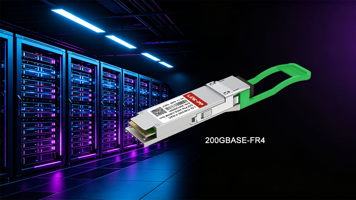
200GBASE-FR4 is a 200 Gigabit Ethernet optical standard designed for mid-reach transmission over single-mode fiber (SMF). In simple terms, it allows network devices—such as switches, routers, and servers—to send data at 200 Gbps over distances of up to 2 kilometers using a compact pluggable transceiver.
The “FR4” naming helps explain how it works:
- F = Fiber (single-mode fiber)
- R = Reach (mid-range, typically up to 2 km)
- 4 = Four optical lanes
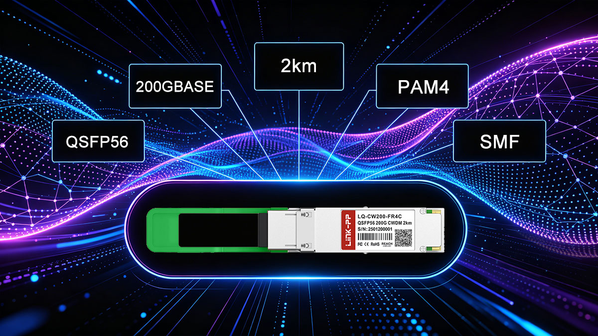
Instead of sending all data through a single channel, 200GBASE-FR4 splits the signal into four separate lanes, each running at 50 Gbps. These lanes are transmitted simultaneously using four different wavelengths (CWDM) and then combined onto a duplex LC fiber pair. This approach increases bandwidth while keeping the physical cabling simple and efficient.
In terms of hardware, 200GBASE-FR4 is most commonly implemented in the QSFP56 form factor, making it suitable for high-density environments where space, power consumption, and scalability are critical.
Where 200GBASE-FR4 Fits in Optical Networking
In modern optical networks, different standards are optimized for different distances and use cases:
- Short-reach (SR): Typically uses multimode fiber for very short distances (tens to hundreds of meters)
- Mid-reach (FR): Uses single-mode fiber for distances up to a few kilometers
- Long-reach (LR/ER): Designed for longer distances, often with higher cost and complexity
200GBASE-FR4 sits in the middle of this spectrum, making it ideal for:
- Data center interconnects (DCI) within a campus
- Leaf-to-spine connections across larger facilities
- Metro-edge links that require moderate distance without long-haul optics
Its value comes from offering a balanced combination of reach, performance, and cost-efficiency. It extends beyond the limits of multimode solutions while avoiding the added complexity of longer-reach technologies.
For many network designs, 200GBASE-FR4 is the practical choice when distances exceed short-reach limits but do not justify long-reach optics, making it a key building block in modern high-speed infrastructure.
🔶 200GBASE-FR4 Specification: Reach, Fiber, and Wavelengths
To understand where 200GBASE-FR4 fits in real deployments, it’s important to look at its core technical characteristics. This standard is designed to deliver 200G Ethernet over single-mode fiber (SMF) with a balance of reach, efficiency, and manageable complexity.
Single-Mode Fiber (SMF) for Stable Transmission
Unlike short-reach optics that rely on multimode fiber, 200GBASE-FR4 operates over single-mode fiber (OS2). This allows for:
- Lower signal attenuation over distance
- Better performance consistency
- Support for longer links without signal distortion
Because of this, FR4 is commonly used in environments where multimode fiber is no longer sufficient, but long-haul solutions are unnecessary.
2 km Reach: The Mid-Reach Sweet Spot
200GBASE-FR4 supports transmission distances of up to 2 kilometers, making it ideal for:
- Data center interconnects within a campus
- Large-scale enterprise networks
- Metro-edge deployments
This “mid-reach” capability fills the gap between short-range SR optics and longer-range LR/ER solutions.
CWDM Wavelengths: Efficient Use of Fiber
One of the defining features of 200GBASE-FR4 is its use of CWDM (Coarse Wavelength Division Multiplexing). Instead of requiring multiple fiber pairs, it transmits multiple signals over different wavelengths on the same fiber pair.
- Four distinct wavelengths are used in the 1310 nm range
- Each wavelength carries an independent data stream
- Signals are multiplexed onto a duplex LC interface
This design reduces cabling complexity while maintaining high throughput.
4 × 50G Optical Lane Structure
At the physical layer, 200GBASE-FR4 uses four parallel lanes, each operating at 50 Gbps (PAM4 modulation):
- Total bandwidth: 4 × 50 Gbps = 200 Gbps
- Each lane is assigned a separate CWDM wavelength
- Data is transmitted simultaneously and recombined at the receiver
This multi-lane architecture is key to achieving high speeds without requiring more fibers.
200GBASE-FR4 Specification Table
| Parameter |
Specification |
| Standard |
200GBASE-FR4 |
| Data Rate |
200 Gbps |
| Modulation |
PAM4 |
| Number of Lanes |
4 lanes |
| Per-Lane Data Rate |
50 Gbps |
| Fiber Type |
Single-Mode Fiber (OS2) |
| Maximum Reach |
Up to 2 km |
| Connector Type |
Duplex LC |
| Wavelengths |
CWDM (4 wavelengths around 1310 nm) |
| Typical Wavelength Range |
~1271 nm, 1291 nm, 1311 nm, 1331 nm |
| Form Factor |
QSFP56 |
| FEC Requirement |
Required (host-side forward error correction) |
| Application |
Data center interconnect, campus, metro-edge |
By combining single-mode fiber, CWDM technology, and a 4-lane architecture, 200GBASE-FR4 achieves a practical balance between performance and deployment simplicity. This is why it has become a preferred choice for mid-range, high-speed optical links in modern network infrastructures.
🔶 200GBASE-FR4 vs. LR4, DR4, and SR4
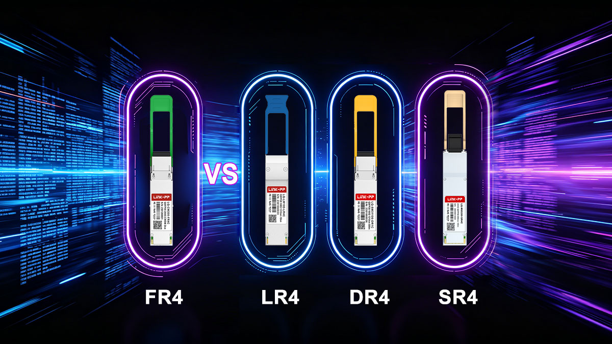
When selecting a 200G optical solution, choosing between FR4, LR4, DR4, and SR4 is not just about speed—they all deliver 200 Gbps. The real differences lie in reach, fiber type, cabling complexity, port density, and deployment scenarios. Understanding these trade-offs helps avoid overdesigning (and overspending) or choosing a solution that cannot meet distance or infrastructure requirements.
Key Differences at a Glance
| Standard |
Reach |
Fiber Type |
Connector Type |
Lane Design |
Cabling Complexity |
Typical Use Case |
| 200GBASE-SR4 |
~100 m |
Multimode (MMF) |
MPO-12 |
4 × 50G parallel |
High |
Short intra-rack / row links |
| 200GBASE-DR4 |
~500 m |
Single-mode (SMF) |
MPO-12 |
4 × 50G parallel |
High |
Data center spine-leaf (longer reach) |
| 200GBASE-FR4 |
~2 km |
Single-mode (SMF) |
Duplex LC |
4 × 50G CWDM |
Low |
Campus / DCI / metro-edge |
| 200GBASE-LR4 |
~10 km |
Single-mode (SMF) |
Duplex LC |
4 × 50G CWDM |
Low |
Metro / longer enterprise links |
Reach: Matching Distance to Design
- SR4 is limited to very short distances (typically ≤100 m), making it suitable for inside-the-rack or row-level connections.
- DR4 extends reach to around 500 m using SMF, but still relies on parallel fibers.
- FR4 covers up to 2 km, making it ideal for campus-scale and inter-building links.
- LR4 pushes further to 10 km, typically used for metro or longer enterprise connections.
Takeaway: If your link distance falls between 500 m and 2 km, 200GBASE-FR4 is usually the most balanced choice.
Fiber Type and Cabling Strategy
- SR4 uses multimode fiber (MMF), which is cost-effective but limited in reach.
- DR4 and SR4 both rely on parallel fiber (MPO) connections, requiring multiple fiber strands.
- FR4 and LR4 use single-mode fiber (SMF) with duplex LC connectors, simplifying cabling.
Why this matters: Parallel fiber (MPO) solutions increase cabling complexity and require more precise infrastructure planning, while duplex LC (used by FR4/LR4) is easier to deploy and scale.
Port Density and Scalability
- MPO-based optics (SR4, DR4) consume more fiber resources per link, which can limit scalability in high-density environments.
- FR4 and LR4, using duplex LC, allow for higher effective port density because fewer fibers are needed per connection.
In practice: Data centers aiming for cleaner cable management and long-term scalability often prefer FR4 over DR4 when reach allows.
Deployment Scenarios
Each standard is optimized for a specific environment:
- 200GBASE-SR4
Best for short, high-density connections within racks or rows using existing MMF infrastructure
- 200GBASE-DR4
Ideal for spine-leaf links within a data center where SMF is used but distances remain under 500 m
- 200GBASE-FR4
Designed for mid-range links (up to 2 km) such as:
- Data center interconnects (DCI) within a campus
- Building-to-building connections
- Metro-edge aggregation
- 200GBASE-LR4
Used for longer-distance links (up to 10 km) where extended reach is required
Choosing the Right Standard
In real-world design, the decision often comes down to this:
- Choose SR4 if you already have MMF and distances are very short
- Choose DR4 if you need SMF but are staying within 500 m
- Choose FR4 if you need up to 2 km with simpler cabling and better scalability
- Choose LR4 only when distances exceed FR4 limits
For many modern networks, 200GBASE-FR4 represents the most practical middle ground, offering enough reach for campus and inter-building links while maintaining manageable cabling and strong scalability.
🔶 QSFP56 Compatibility and Host Requirements
Understanding QSFP56 compatibility is one of the most critical aspects of deploying 200GBASE-FR4. Many real-world issues don’t come from the optical standard itself, but from mismatches between the transceiver, host port, and system firmware.
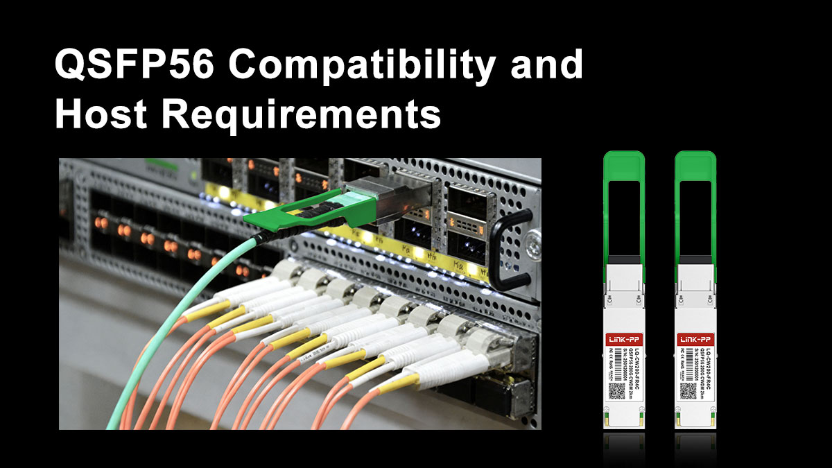
QSFP56 Form Factor: What to Expect
200GBASE-FR4 is typically implemented in the QSFP56 form factor, which is designed for 200G Ethernet applications using 4 electrical lanes.
Key characteristics of QSFP56:
- Supports 4 × 50G electrical lanes (PAM4)
- Backward mechanical compatibility with QSFP+/QSFP28 (but not performance compatibility)
- Designed for high-density switch and router ports
This means that to use a 200GBASE-FR4 module, your device must have a native QSFP56 port that supports 200G signaling—not just a physically similar slot.
Electrical Interface: 4 × 50G PAM4
At the electrical level, QSFP56 ports operate using:
- 4 lanes at 50 Gbps each
- PAM4 modulation (Pulse Amplitude Modulation with 4 levels)
This is fundamentally different from older QSFP28 ports, which use:
- 4 × 25 Gbps
- NRZ signaling
Why this matters: A QSFP28 port cannot drive a QSFP56 (200G) optical module, even if the connector looks identical. The signaling and bandwidth requirements are completely different.
Host-Side Requirements: More Than Just the Port
To successfully deploy 200GBASE-FR4, the host system (switch, NIC, or router) must support several key features:
1. Forward Error Correction (FEC)
- FEC is required for 200GBASE-FR4 operation
- Typically implemented as RS-FEC (Reed-Solomon FEC) on the host side
- Ensures signal integrity when using PAM4 modulation over distance
If the host does not support the correct FEC mode, the link may fail to initialize or experience high error rates.
2. Firmware and Vendor Compatibility
Many network vendors enforce transceiver compatibility checks:
- Some systems only accept vendor-coded or approved modules
- Third-party optics may require coding or unlocking
- Firmware mismatches can prevent link establishment
Best practice: Always verify compatibility with your switch or NIC vendor before purchasing.
3. Port Configuration and Breakout Limitations
Unlike some parallel optics:
- 200GBASE-FR4 is not designed for breakout into multiple lower-speed links
- It operates as a single 200G logical interface
Attempting unsupported configurations (e.g., mixing FR4 with breakout expectations) can lead to confusion during deployment.
Why Compatibility Issues Are So Common
In practice, most deployment problems with 200GBASE-FR4 come from assumptions such as:
- “If it fits, it should work” (physical compatibility ≠ electrical compatibility)
- Mixing QSFP56 and QSFP-DD expectations
- Ignoring FEC requirements
- Overlooking vendor restrictions
These issues are especially common when upgrading from 100G to 200G environments, where legacy infrastructure may not fully support newer signaling standards.
Practical Takeaway
Before deploying 200GBASE-FR4, always confirm:
- Your device has true QSFP56 200G-capable ports
- The system supports PAM4 signaling and required FEC modes
- The transceiver is compatible with your vendor platform
Getting these factors right upfront helps avoid costly troubleshooting and ensures a stable, high-performance optical link.
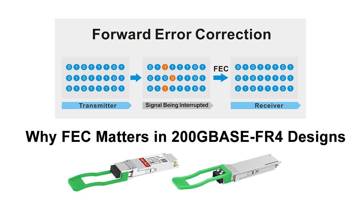
🔶 Why FEC Matters in 200GBASE-FR4 Designs
In 200GBASE-FR4 links, Forward Error Correction (FEC) is not optional—it is a fundamental requirement for achieving stable, error-free transmission at 200 Gbps. Without it, the link would be highly susceptible to noise, signal distortion, and bit errors.
Why FEC Is Required in 200GBASE-FR4
The need for FEC comes from how 200GBASE-FR4 transmits data:
- It uses PAM4 modulation, which encodes 2 bits per symbol
- Each lane runs at 50 Gbps, pushing the limits of signal integrity
- Signals travel over up to 2 km of single-mode fiber
Compared to traditional NRZ signaling, PAM4 is more bandwidth-efficient but less tolerant to noise. The signal levels are closer together, making it easier for the receiver to misinterpret data.
FEC solves this problem by adding redundancy to the transmitted data, allowing the receiver to detect and correct errors in real time.
How FEC Works (Simplified)
At a high level, FEC operates as follows:
- The transmitter adds extra error-correction bits to the data stream
- The signal is sent over the optical link
- The receiver uses these extra bits to identify and correct errors
In 200GBASE-FR4, the most commonly used method is:
- RS-FEC (Reed-Solomon Forward Error Correction)
This type of FEC is specifically designed for high-speed Ethernet and is highly effective at correcting burst errors typical in optical links.
Impact on Real-World Link Reliability
FEC directly improves the reliability and usability of 200GBASE-FR4 links in several ways:
1. Lower Bit Error Rate (BER)
- Without FEC: Higher raw error rates due to PAM4 limitations
- With FEC: Errors are corrected before affecting higher-layer protocols
This ensures stable communication even near the edge of the link budget.
2. Extended Effective Reach
FEC allows signals to travel closer to the 2 km limit without degradation:
- Compensates for attenuation and dispersion
- Makes mid-reach transmission practical and predictable
3. Greater Tolerance to Real-World Conditions
In actual deployments, links are affected by:
- Connector losses
- Fiber imperfections
- Temperature variations
- Aging components
FEC provides a buffer against these factors, reducing the risk of intermittent failures.
Trade-Offs: What FEC Costs You
While FEC is essential, it does introduce small trade-offs:
- Latency: Slight increase due to encoding and decoding (typically negligible in most applications)
- Processing overhead: Requires support from the host system (switch/NIC)
In most data center and enterprise environments, these trade-offs are minimal compared to the reliability benefits.
Why Host Support Is Critical
FEC is typically implemented on the host side, not inside the optical module itself. This means:
- The switch or NIC must support the correct FEC mode (e.g., RS-FEC)
- Mismatched FEC settings between two ends can cause link failure
- Some platforms require manual configuration of FEC settings
Common issue: A link may not come up even when optics and fiber are correct—simply because FEC is disabled or misconfigured.
Practical Takeaway
For 200GBASE-FR4, FEC is what makes high-speed transmission over 2 km of single-mode fiber reliable and deployable in real environments.
To ensure a stable link:
- Verify that your equipment supports RS-FEC for 200G
- Ensure both ends of the link use matching FEC settings
- Treat FEC as a core part of the system design, not an optional feature
By properly accounting for FEC, you significantly reduce the risk of errors, improve link stability, and ensure that your 200GBASE-FR4 deployment performs as expected.
🔶 Common 200GBASE-FR4 Deployment Mistakes to Avoid
Even when the specification is well understood, 200GBASE-FR4 deployments can fail due to a handful of predictable mistakes. Most of these issues are not caused by the optic itself, but by mismatched assumptions about fiber, ports, or system compatibility. Avoiding the following pitfalls can save significant time and cost during rollout.
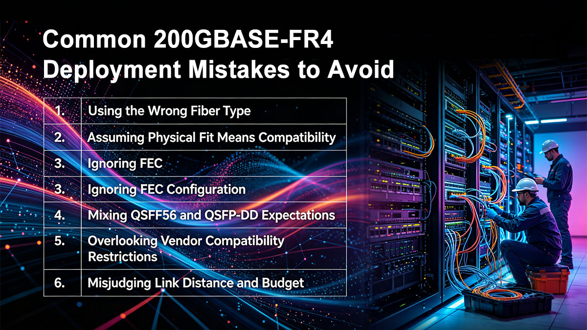
1. Using the Wrong Fiber Type
Mistake: Attempting to use multimode fiber (MMF) instead of single-mode fiber (SMF)
- 200GBASE-FR4 is designed exclusively for single-mode fiber (OS2)
- It operates at wavelengths around 1310 nm, which are not compatible with MMF transmission characteristics
What happens: The link will either fail to establish or suffer severe signal loss.
Best practice: Always verify that your infrastructure uses OS2 single-mode fiber with duplex LC connectors before deploying FR4 optics.
2. Assuming Physical Fit Means Compatibility
Mistake: Plugging a QSFP56 FR4 module into any QSFP port and expecting it to work
- QSFP+, QSFP28, and QSFP56 may look identical
- But electrical signaling is different (NRZ vs PAM4)
What happens: The module may be recognized physically, but the link will not come up due to incompatible signaling.
Best practice: Confirm that your switch or NIC supports native 200G QSFP56 ports with PAM4 signaling.
3. Ignoring FEC Configuration
Mistake: Overlooking Forward Error Correction (FEC) settings
- 200GBASE-FR4 requires RS-FEC for stable operation
- FEC must be supported and properly configured on both ends
What happens:
- Link instability
- High error rates
- Or complete link failure
Best practice: Ensure both devices have matching FEC settings enabled before troubleshooting other issues.
4. Mixing QSFP56 and QSFP-DD Expectations
Mistake: Assuming QSFP-DD modules or ports are interchangeable with QSFP56
- QSFP-DD supports 8 electrical lanes, while QSFP56 supports 4 lanes
- They are not directly interchangeable
What happens:
- Mechanical incompatibility in some cases
- Electrical mismatch in others
Best practice: Match the module strictly to the correct port type (QSFP56 for FR4) unless your platform explicitly supports cross-compatibility.
5. Overlooking Vendor Compatibility Restrictions
Mistake: Using third-party optics without checking platform support
- Many vendors implement transceiver validation or locking mechanisms
- Unsupported modules may be rejected or limited in functionality
What happens:
- Ports may shut down
- Warning messages or degraded performance
Best practice: Use vendor-approved or properly coded compatible transceivers for your specific switch or NIC.
6. Misjudging Link Distance and Budget
Mistake: Assuming all FR4 links will reliably reach 2 km without considering real conditions
- Connector loss, patch panels, and fiber quality all impact performance
What happens:
- Marginal links that work intermittently
- Unexpected signal degradation
Best practice: Plan with margin by considering:
- Total link loss (connectors, splices)
- Fiber quality and age
- Environmental factors
7. Expecting Breakout Functionality
Mistake: Trying to split a 200GBASE-FR4 link into multiple lower-speed links
- FR4 uses wavelength multiplexing over duplex fiber, not parallel lanes for breakout
What happens:
- Unsupported configuration
- No link establishment
Best practice: Use FR4 as a single 200G link, and choose DR4 or SR4 if breakout is required.
Practical Takeaway
Most 200GBASE-FR4 deployment issues are preventable with proper planning. Before installation, always confirm:
- Correct fiber type (SMF, OS2)
- True QSFP56 port compatibility
- Proper FEC configuration
- Verified vendor support
By addressing these common mistakes early, you can ensure a smoother deployment and a more reliable high-speed optical network.
🔶 Common Questions about 200GBASE-FR4
Q1: What is 200GBASE-FR4 used for?
200GBASE-FR4 is used for 200G Ethernet transmission over single-mode fiber at distances up to 2 km. Typical applications include:
- Data center interconnects (DCI) within a campus
- Spine-to-leaf connections across large facilities
- Enterprise and metro-edge network links
Q2: Is 200GBASE-FR4 single-mode or multimode?
200GBASE-FR4 uses single-mode fiber (SMF) only. It operates around the 1310 nm wavelength range and is not compatible with multimode fiber.
Q3: What is the maximum distance of 200GBASE-FR4?
The standard supports up to 2 kilometers over single-mode fiber under typical conditions. Actual performance depends on link quality, connector loss, and overall optical budget.
Q4: What connector does 200GBASE-FR4 use?
It uses a duplex LC connector, which simplifies cabling compared to MPO-based solutions.
Q5: What form factor is used for 200GBASE-FR4?
Most 200GBASE-FR4 transceivers are available in the QSFP56 form factor, designed for 200G Ethernet applications.
Q6: Does 200GBASE-FR4 require FEC?
Yes, Forward Error Correction (FEC) is required. Typically, RS-FEC is used to ensure reliable transmission with PAM4 signaling.
Q7: Can 200GBASE-FR4 work in QSFP28 ports?
No. QSFP28 ports support 100G (NRZ), while 200GBASE-FR4 requires QSFP56 ports with PAM4 signaling.
Q8: What is the difference between FR4 and DR4?
- FR4: Uses CWDM wavelengths over duplex LC fiber, up to 2 km
- DR4: Uses parallel fibers (MPO), up to ~500 m
FR4 is better for longer distances with simpler cabling, while DR4 is used for shorter SMF links with parallel optics.
Q9: Can 200GBASE-FR4 be used for breakout connections?
No. 200GBASE-FR4 is designed as a single 200G link and does not support breakout into multiple lower-speed interfaces.
Q10: When should I choose 200GBASE-FR4?
Choose 200GBASE-FR4 when:
- Your link distance is between 500 m and 2 km
- You prefer duplex LC over MPO cabling
- You need a balance of reach, simplicity, and scalability
🔶 How to Choose a 200GBASE-FR4 Transceiver for Data Centers
Selecting the right 200GBASE-FR4 transceiver is not just about matching a specification—it’s about ensuring reliable operation, long-term scalability, and predictable performance in your actual network environment. The following criteria reflect what engineers and buyers should evaluate before making a purchase.
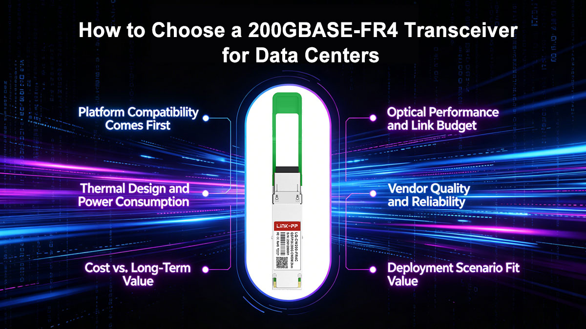
♦ Platform Compatibility Comes First
Before anything else, confirm that the transceiver will work with your hardware:
- Ensure your switch or NIC supports QSFP56 200G ports (PAM4 signaling)
- Verify FEC requirements (typically RS-FEC) are supported and enabled
- Check whether your vendor enforces transceiver compatibility or coding restrictions
A mismatch here is the most common reason for deployment failure—even when everything else is correct.
♦ Optical Performance and Link Budget
Not all modules perform equally under real conditions. Pay attention to:
- Transmit power and receiver sensitivity
- Link budget margin for connectors, patch panels, and aging fiber
- Stability across the full 2 km reach range
If your link is close to the maximum distance, choosing a higher-quality module with better tolerance can prevent intermittent issues.
♦ Thermal Design and Power Consumption
200G optics generate more heat than lower-speed modules, especially in high-density environments.
- Check the power consumption (typically ~4–6W for FR4)
- Ensure your equipment supports proper airflow and cooling
- Consider thermal performance in fully populated switch scenarios
Poor thermal planning can lead to throttling, reduced lifespan, or unexpected link instability.
♦ Vendor Quality and Reliability
In production networks, consistency matters more than theoretical specs:
- Look for suppliers with proven manufacturing quality and testing standards
- Check for interoperability validation across major switch vendors
- Ensure availability of technical support and documentation
A reliable vendor reduces the risk of compatibility issues and simplifies troubleshooting.
♦ Cost vs. Long-Term Value
While price is always a factor, the cheapest option is not always the best:
- Low-cost modules may have limited compatibility or weaker performance margins
- Higher-quality options often provide better stability and lower failure rates
- Consider the total cost of ownership, including downtime and replacement risk
For many data centers, investing slightly more upfront avoids costly operational issues later.
♦ Deployment Scenario Fit
Match the module to your actual use case:
- 500 m – 2 km links: 200GBASE-FR4 is ideal
- Shorter links with MPO infrastructure: DR4 may be more suitable
- Longer distances (>2 km): Consider LR4 instead
Choosing the right standard ensures both performance and cost efficiency.
♦ Practical Deployment Checklist
Before purchasing a 200GBASE-FR4 transceiver, confirm:
- QSFP56 port compatibility ✔
- FEC support and configuration ✔
- Single-mode fiber (OS2) infrastructure ✔
- Vendor compatibility and coding ✔
- Adequate thermal environment ✔
If you are looking for cost-effective, fully tested, and vendor-compatible 200GBASE-FR4 modules, you can explore the LINK-PP Official Store. It offers a range of optical transceivers designed for real-world deployment, with compatibility across major networking platforms and consistent quality control.
Choosing a trusted supplier hel


