
The GLC-MMD stands as a cornerstone in enterprise networking, serving as the industry-standard 1000BASE-SX SFP transceiver for short-reach Gigabit Ethernet applications. Utilizing an 850nm VCSEL laser and a dual-LC connector, this module is specifically engineered to deliver reliable data transmission over multimode fiber. As modern data centers transition toward more cost-effective hardware strategies, high-quality GLC-MMD Cisco compatible alternatives have become essential components, offering the same technical precision and digital diagnostics monitoring capabilities as original equipment.
Understanding the technical framework of the GLC-MMD alternative is vital for maintaining network integrity and optimizing fiber spans. This article provides a deep dive into the physical layer specifications, from transmission distance limits on multimode fiber to seamless EEPROM integration with Cisco Catalyst and Nexus platforms. By exploring the critical parameters of launch power, receiver sensitivity, and interoperability testing, we aim to provide the technical data necessary for a robust, high-performance optical link.
📋 Understanding the Physical Layer of GLC-MMD Cisco Alternative
The physical layer of a GLC-MMD alternative defines the hardware characteristics and optical mechanisms that ensure reliable high-speed data transmission. By adhering to rigorous engineering standards, GLC-MMD compatible modules like the LINK-PP LS-MM851G-S5C 850nm 1G SFP provide a seamless physical interface between the electrical circuitry of the switch and the optical fiber network.
850nm Vertical-Cavity Surface-Emitting Laser (VCSEL) Technology
The core of the GLC-MMD alternative is the 850nm VCSEL, a specialized semiconductor laser that emits light perpendicular to its top surface. This technology is preferred for short-range 1000BASE-SX applications because it combines high-speed modulation capabilities with low power consumption and high reliability.
The LINK-PP LS-MM851G-S5C utilizes this VCSEL technology to ensure a stable optical output that meets the stringent requirements of the IEEE 802.3z standard. Unlike edge-emitting lasers, the VCSEL’s circular beam profile allows for highly efficient coupling into multimode fibers, reducing signal loss at the launch point.
Dual-LC Duplex Connector Architecture
To facilitate high-density networking, the GLC-MMD alternative features a Dual-LC duplex connector interface. This small-form-factor design uses a 1.25mm ceramic ferrule, effectively doubling the port density on switch line cards compared to older SC-style connectors.
The architecture ensures a secure "push-pull" latching mechanism that maintains precise physical alignment between the transceiver's internal optics and the fiber patch cable. In modules like the LINK-PP LS-MM851G-S5C, the connector housing is built to withstand repeated insertions while maintaining a low insertion loss, which is critical for maintaining a healthy link budget.
Photodiode Sensitivity and Optical Receiver Parameters
On the receiving end, the module employs a high-sensitivity PIN photodiode designed to convert incoming 850nm light pulses back into electrical signals. Receiver sensitivity is a pivotal parameter, as it determines the minimum optical power required for the transceiver to maintain a Bit Error Rate (BER) of less than 10⁻¹². For a high-performance compatible alternative like the LINK-PP LS-MM851G-S5C, the receiver sensitivity typically reaches as low as -18dBm, ensuring reliable performance even over maximum-length fiber runs where signal attenuation is more pronounced.
Beyond sensitivity, the receiver is defined by its saturation or "optical overload" point, which is generally rated at 0dBm. This wide dynamic range allows the module to handle high-intensity signals from very short patch cables without damaging the photodetector or causing signal clipping. By maintaining an operating wavelength range of 830nm to 870nm, the LS-MM851G-S5C ensures that it captures the full spectral width of the incoming signal, providing a stable and error-free connection across diverse multimode environments.
Form Factor Compliance: SFP Multi-Source Agreement (MSA)
The GLC-MMD alternative is built strictly according to the SFP Multi-Source Agreement (MSA), which dictates the physical dimensions, electrical interface, and signaling protocols. This compliance ensures that the module is physically hot-swappable and electrically compatible with any host slot designed for standard SFPs.
By following the SFF-8472 standard within the MSA, the LINK-PP LS-MM851G-S5C provides a standardized I2C serial interface. This allows the host Cisco switch to identify the module's capabilities and access real-time operating data, ensuring that the third-party hardware operates identically to its OEM counterpart.
📋 Transmission Distance Limits for GLC-MMD Alternative on Multimode Fiber
The transmission range of a GLC-MMD alternative is primarily dictated by the grade of the multimode fiber infrastructure and the inherent modal bandwidth of the cable. While the GLC-MMD compatible module is designed for short-reach applications, its effective distance varies significantly depending on whether it is deployed over legacy 62.5-micron or modern laser-optimized 50-micron fiber.
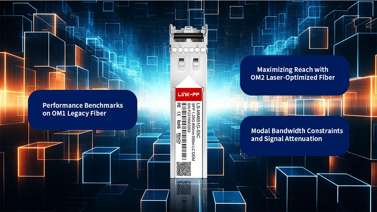
Performance Benchmarks on OM1 Legacy Fiber
OM1 fiber, characterized by its 62.5/125µm core diameter, represents the "legacy" tier of multimode cabling. Due to its large core size and lower modal bandwidth, the GLC-MMD alternative faces significant challenges with differential mode delay (DMD) when pushed beyond its rated limits.
When using the GLC-MMD compatible alternative over OM1 fiber, the maximum transmission distance is capped at 275m (902 feet) for Gigabit Ethernet. Exceeding this distance often results in excessive bit errors and link instability, as the light pulses begin to overlap and become indistinguishable to the receiver.
Maximizing Reach with OM2 Laser-Optimized Fiber
OM2 fiber transitions to a 50/125µm core, providing a higher modal bandwidth that allows the GLC-MMD alternative to extend its reach further than OM1. This "standard" 50-micron fiber was the first step toward optimizing cables for the higher speeds required by vertical-cavity surface-emitting lasers (VCSELs).
Deploying the GLC-MMD compatible module on OM2 cabling extends the reliable transmission distance to 550m (1,804 feet). This makes it an ideal solution for backbone links within a single building or across smaller campus environments where a 550-meter threshold is sufficient to cover most horizontal and vertical cabling runs.
Modal Bandwidth Constraints and Signal Attenuation
The primary bottleneck for 850nm optical links is modal dispersion, a phenomenon where different modes of light travel at different speeds through the fiber, causing the signal pulses to spread out over distance. As these pulses overlap, the receiver's ability to distinguish between "0s" and "1s" diminishes, leading to high bit-error rates. Additionally, signal attenuation at the 850nm wavelength is relatively high — typically around 3.5dB/km — which further limits the power budget available for the link.
For a GLC-MMD alternative like the LINK-PP LS-MM851G-S5C, the interplay between bandwidth and attenuation determines the maximum effective reach. The following table highlights the standardized performance constraints for the two most common legacy multimode fiber grades:
| Fiber Type |
Core Diameter |
Modal Bandwidth |
Max Distance (1.25Gbps) |
| OM1 |
62.5/125μm |
200MHz·km |
275m |
| OM2 |
50/125μm |
500MHz·km |
550m |
When deploying these modules, it is essential to account for the total "insertion loss" of the link, which includes the attenuation of the fiber itself plus the losses incurred at every patch panel and connector interface. Even if the cable length is within the 550-meter limit for OM2, excessive bends or dirty connectors can increase attenuation beyond the module's receiver sensitivity threshold, causing link instability.
📋 Core Technical Specifications of the GLC-MMD Alternative Module
The performance of a GLC-MMD alternative is governed by a strict set of electrical and optical parameters that ensure high-speed data integrity. These specifications define the operational boundaries of the transceiver, ensuring it meets the rigorous demands of enterprise-grade switching and storage area networks.
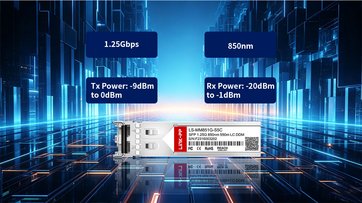
Data Rate Support: 1.25Gbps Ethernet and 1.063Gbps Fibre Channel
The GLC-MMD compatible alternative is a versatile multi-rate transceiver designed primarily for 1000BASE-SX Gigabit Ethernet applications, operating at a line rate of 1.25Gbps. This allows it to handle standard IP traffic across local area networks with high efficiency and minimal latency.
In addition to Ethernet, these modules typically support 1G Fibre Channel (1.063Gbps), making them suitable for legacy storage area network (SAN) environments. This dual-protocol support ensures that the module can be deployed across various hardware platforms, from standard network switches to dedicated storage controllers.
Launch Power (Tx) and Receive Power (Rx) Ranges
The optical power budget is a critical factor for link reliability, defined by the difference between the transmitter's output and the receiver's threshold. A GLC-MMD compatible alternative like the LINK-PP LS-MM851G-S5C SFP module features a transmit (Tx) launch power ranging from -9dBm to 0dBm. This range ensures the signal is strong enough to traverse the fiber without being so powerful that it overwhelms the receiver.
On the receiving end, the module is designed to operate within an optical receive (Rx) power range of -20dBm to -1dBm. Maintaining the signal within these specific decibel parameters is essential for preventing bit errors; signals falling below -20dBm are too weak to be "read," while those above -1dBm risk saturating or damaging the sensitive photodiode.
Center Wavelength Tolerance and Spectral Width
Precision in light emission is vital for minimizing chromatic dispersion. A high-quality GLC-MMD compatible alternative operates at a nominal center wavelength of 850nm, but it must maintain a tight tolerance — typically between 830nm and 870nm. This consistency ensures that the light travels predictably through the multimode fiber's graded-index core.
Spectral width is another key metric, usually limited to a maximum of 0.85nm. A narrow spectral width reduces the amount of "color" spreading as the pulse travels, which is critical for maintaining signal clarity over the full rated distance of 550m on OM2 fiber.
Power Consumption and Thermal Dissipation Standards
Efficiency and heat management are paramount in high-density switch environments. A standard GLC-MMD alternative is engineered for low power consumption, typically drawing less than 1W of total power. This low energy footprint reduces the electrical strain on the host switch's backplane and contributes to lower operational costs.
Thermal dissipation is managed through the module's metal housing, which acts as a heat sink. These transceivers are usually rated for a commercial operating temperature range of 0°C to 70°C (32°F to 158°F). Proper thermal regulation prevents "wavelength drift" and extends the lifespan of the internal VCSEL laser, ensuring long-term stability in climate-controlled data centers.
📋 Digital Diagnostics Monitoring (DDM) Features in GLC-MMD Cisco Alternative
Digital diagnostics monitoring, also known as digital optical monitoring (DOM), is a critical feature that allows network administrators to view the real-time operating parameters of the SFP. By providing a window into the "health" of the optical link, DDM-enabled GLC-MMD compatible alternatives ensure that potential hardware failures or fiber degradations are identified before they cause significant downtime.
Real-time Monitoring of Optical Transmit and Receive Power
One of the most valuable aspects of DDM is the ability to monitor the strength of the light being sent and received by the module. This data is essential for verifying that the link is operating within the specified optical budget and for identifying issues related to cable attenuation or connector contamination.
- Transmit (Tx) Power Monitoring: This tracks the output of the 850nm VCSEL laser. A sudden drop in Tx power often indicates laser aging or internal component failure.
- Receive (Rx) Power Monitoring: This measures the intensity of the light arriving from the remote end. By comparing the Rx power against the sensitivity threshold (e.g., -18dBm), technicians can quickly determine if a link failure is due to a faulty transmitter at the far end or a break in the fiber path.
Operating Temperature and Voltage Tracking
The GLC-MMD alternative operates within a specific "Safe Zone" for both heat and power. DDM continuously tracks these environmental variables, providing the switch with the data necessary to trigger alarms if the module begins to operate outside of its designed tolerances.
Monitoring the internal temperature is particularly important in high-density rack environments where airflow may be restricted. If the module exceeds its 70°C rating, the frequency of the laser can shift, leading to packet loss. Similarly, tracking the supply voltage ensures that the host switch is providing stable power, protecting the delicate internal circuitry from voltage spikes or sags that could lead to intermittent reboots.
Laser Bias Current Supervision
Laser bias current is the "drive" current applied to the VCSEL to initiate light emission. By supervising this specific metric through DDM, the system can monitor the efficiency of the laser diode over its entire lifecycle.
As a laser ages, it naturally requires more current to produce the same amount of optical output power. A DDM alert indicating an unusually high bias current serves as an "early warning system," signaling that the laser is reaching the end of its functional life. This allows for scheduled replacements during maintenance windows rather than responding to an emergency "link down" event.
Utilizing DDM Data for Predictive Network Maintenance
Integrating DDM data into a centralized network management system transforms reactive troubleshooting into a predictive maintenance strategy. By analyzing historical trends in the diagnostics data, administrators can spot patterns of gradual degradation that would otherwise go unnoticed.
- Trend Analysis: Monitoring a slow, steady decline in Rx power over several months can help identify an accumulation of dust on a fiber bulkhead or a patch cord that is being slowly pinched or bent.
- Threshold Alerting: Administrators can set custom SNMP traps based on DDM values. For instance, an alert can be triggered if the temperature rises by 10% above the baseline, allowing for a check of the data center's cooling system before the hardware enters a critical state.
📋 GLC-MMD Alternative Module Compatibility and Interoperability Testing
Compatibility is the most critical factor when integrating third-party transceivers into a branded network environment. Ensuring that a GLC-MMD alternative module is recognized and accepted by the host switch requires precise internal programming and rigorous cross-platform verification.
EEPROM Coding for Cisco Catalyst and Nexus Switch Recognition
For a Cisco switch to accept an SFP module, the transceiver’s internal EEPROM must contain specific coded information. This data includes the vendor name, part number, serial number, and a unique security check code that identifies the module as a "GLC-MMD" type.
High-quality third-party compatible alternatives are pre-programmed with these standardized data structures to ensure they are immediately recognized by the Cisco IOS or NX-OS operating systems. This allows the switch to automatically configure the port with the correct parameters for 1000BASE-SX transmission without requiring manual intervention
Multi-Vendor Hardware Interfacing Strategies
While the primary focus is often on Cisco systems, many modern data centers operate in a multi-vendor environment. A robust GLC-MMD alternative is designed to be interoperable across various hardware brands, such as Arista, Juniper, or Dell, by adhering to the SFP Multi-Source Agreement (MSA).
Interoperability testing involves verifying that the electrical signals and data protocols remain consistent when connecting a Cisco-coded alternative to a different brand's switch. This strategy ensures that the module can maintain a stable link even when bridging connections between disparate hardware platforms.
Resolving "Unknown Transceiver" Software Errors
A common challenge with third-party modules is the "Unknown Transceiver" or "Unsupported Transceiver" error message triggered by the switch software. This usually occurs when the switch's security algorithm does not recognize the signature in the module's EEPROM.
To resolve this, reputable compatible alternatives use sophisticated coding that mimics the original manufacturer's ID. Furthermore, administrators can use specific software commands, such as “service unsupported-transceiver”, to allow the switch to utilize the module while maintaining full monitoring capabilities.
Firmware Versioning for Third-Party GLC-MMD Alternatives
As networking equipment manufacturers release software updates and new firmware versions, the requirements for module recognition can change. Third-party manufacturers must keep their transceiver firmware updated to ensure ongoing compatibility with the latest switch operating systems.
The firmware inside the GLC-MMD alternative manages how the module communicates with the host system's I2C bus. Proper version control ensures that even as switches are patched for security or performance, the transceiver remains fully functional and continues to report accurate DDM data to the management console.
📋 Installation and Cabling Best Practices for GLC-MMD Compatible Alternative
The longevity and performance of a GLC-MMD optical link depend heavily on proper handling and installation techniques. Even the most robust compatible transceiver can suffer from signal degradation if the physical connection is compromised by poor cabling habits or environmental contaminants.
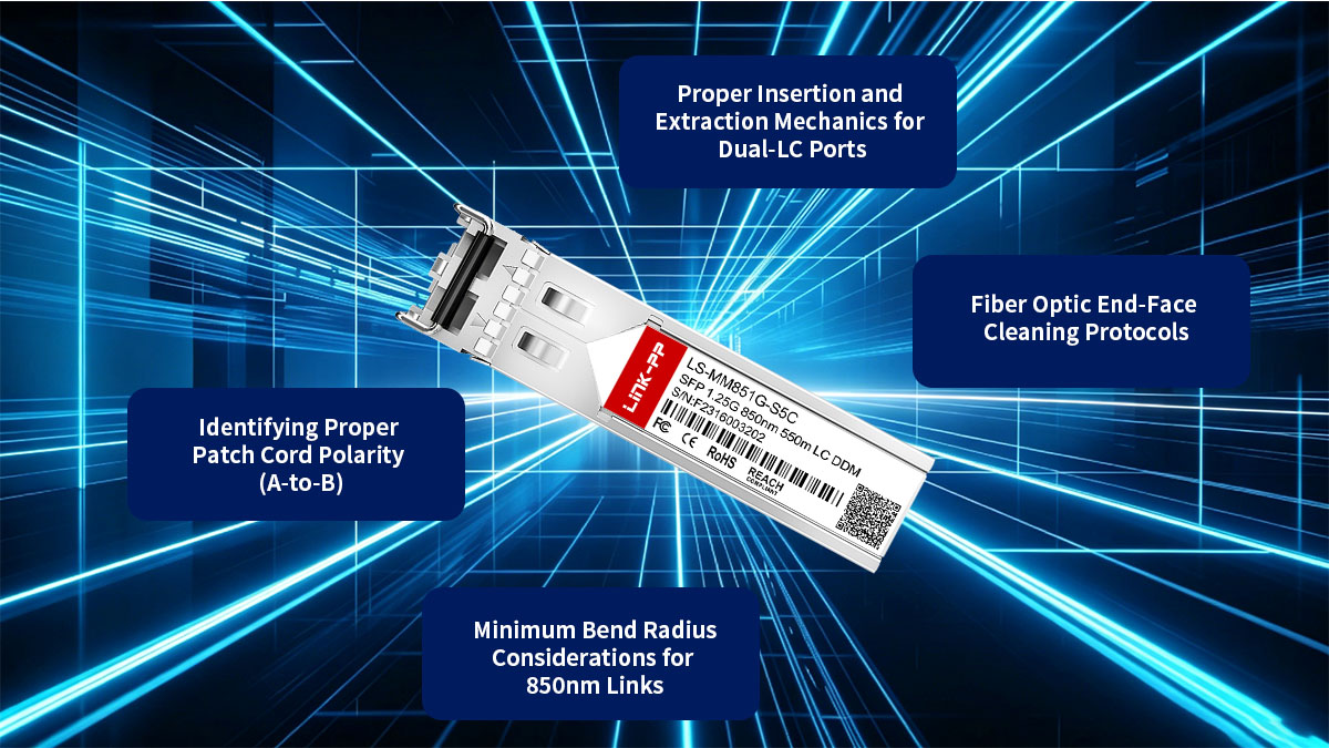
Proper Insertion and Extraction Mechanics for Dual-LC Ports
Installing a GLC-MMD alternative requires a delicate touch to avoid damaging the switch's backplane or the transceiver’s internal pins. The SFP is designed for hot-swapping, but the mechanical alignment must be precise to ensure a successful electrical connection.
- Insertion: Align the module with the SFP slot and slide it in until you hear a distinct "click," which indicates the locking bale has engaged. Never force a module; if there is resistance, check for debris or ensure the module is oriented correctly.
- Extraction: Always flip the bale cladding or lever downward before pulling the module out. This mechanism retracts the locking tab, allowing the transceiver to slide out smoothly without putting undue stress on the port's internal housing.
Fiber Optic End-Face Cleaning Protocols
Contamination is the leading cause of failure in 850nm optical links. Even a microscopic dust particle on the LC connector end-face can block the light path or cause reflections that interfere with the VCSEL laser.
To ensure peak performance, always follow a "Inspect, Clean, Inspect" workflow. Use dedicated fiber cleaning tools, such as lint-free wipes with isopropyl alcohol or specialized "one-click" cleaners, before inserting the fiber into the GLC-MMD alternative transceiver. Never touch the end-face with your fingers, as skin oils are extremely difficult to remove and will permanently degrade the optical signal.
Identifying Proper Patch Cord Polarity (A-to-B)
Establishing a successful link between two GLC-MMD compatible alternatives requires correct fiber polarity, ensuring that the transmit (Tx) side of one module connects to the receive (Rx) side of the other.
- Duplex LC Configuration: Standard multimode patch cords use a "crossed" or A-to-B polarity. This means the fiber originating at the Tx port on Switch A arrives at the Rx port on Switch B.
- Troubleshooting Polarity: If you have a "link down" status despite having light at both ends, the most likely culprit is a "straight-through" (A-to-A) cable. Swapping the LC connectors at one end of the patch cord usually resolves this issue.
Minimum Bend Radius Considerations for 850nm Links
Fiber optic cables are sensitive to physical deformation. Bending a cable too sharply causes "macro-bending" loss, where the light escapes the fiber core, leading to a significant drop in Rx power as reported by the DDM.
For standard 50/125µm or 62.5/125µm multimode fiber, the minimum bend radius is typically 10 to 20 times the outer diameter of the cable. Maintaining gentle curves in your cable management trays prevents micro-fractures in the glass and ensures that the GLC-MMD alternative module operates within its intended optical budget, avoiding intermittent "flapping" or total link failure.
📋 Troubleshooting Common GLC-MMD Cisco Alternative Connection Issues
Even with high-quality components, optical links can occasionally encounter connectivity hurdles due to environmental factors or configuration mismatches. Effective troubleshooting requires a systematic approach, moving from physical layer inspections to software-based diagnostic analysis to restore link stability quickly.
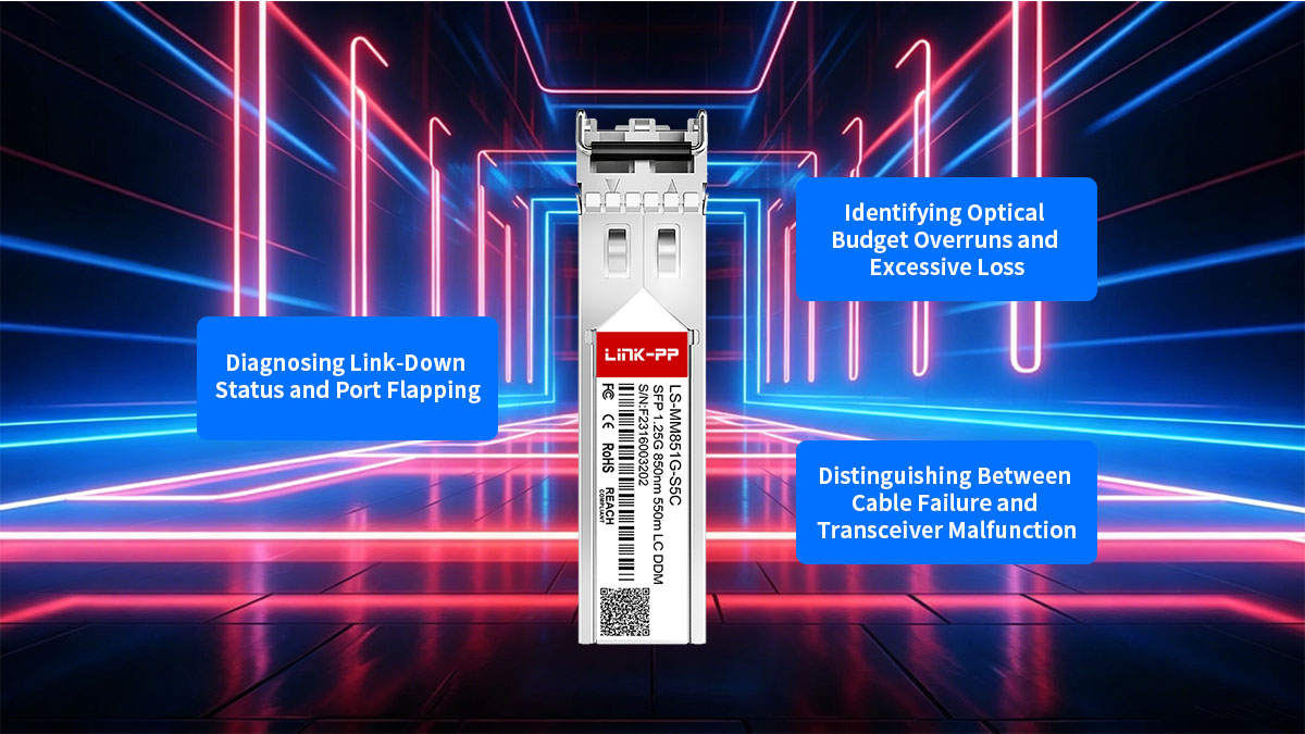
Diagnosing Link-Down Status and Port Flapping
A "Link-Down" status indicates a total loss of signal, while "port flapping" refers to a link that repeatedly goes up and down. To diagnose these issues, first check the physical seating of the GLC-MMD alternative and ensure the port is not administratively disabled in the switch configuration.
Port flapping is often caused by marginal signal levels or mismatched auto-negotiation settings. If the DDM readings show the optical power is oscillating near the receiver's threshold, the link may struggle to remain synchronized. In such cases, forcing the speed to 1000Mbps and disabling auto-negotiation can sometimes stabilize the connection.
Identifying Optical Budget Overruns and Excessive Loss
Optical budget overruns occur when the total decibel loss along the fiber path exceeds the module’s designed capability. This is frequently caused by using excessive lengths of legacy OM1 fiber or having too many intermediate patch panels and splices, each adding its own increment of insertion loss.
To identify this, use the DDM feature to compare the Tx power at one end with the Rx power at the other. If the difference is significantly greater than the expected loss (roughly 3.5dB/km for 850nm MMF plus 0.75dB per connector), you are likely facing excessive loss. Cleaning the fiber end-faces or replacing a high-loss patch cable is usually the required fix.
Distinguishing Between Cable Failure and Transceiver Malfunction
When a link fails, it is essential to determine whether the fault lies within the GLC-MMD alternative module itself or the external cabling. A "loopback test" is the most effective method: connect the module's Tx port directly to its own Rx port using a known-good patch cable.
If the port comes "up" during the loopback test and DDM shows healthy power levels, the transceiver is functional, pointing to a fault in the long-haul fiber run or the remote module. Conversely, if the loopback fails or the laser bias current is reported as out of range, the transceiver has likely suffered a hardware failure and requires replacement.
📋 Key Takeaways on GLC-MMD 850nm SFP Technical Data and Seamless Integration
Successfully integrating a GLC-MMD alternative requires a comprehensive understanding of its physical layer, technical limits, and software compatibility. By adhering to the 850nm VCSEL standard and leveraging Digital Diagnostics Monitoring (DDM), network administrators can achieve the same level of performance and reliability as original equipment. Key factors for a stable link include:
- Precision Specs: Maintaining a transmit power between -9dBm and 0dBm with a receiver sensitivity of -18dBm.
- Infrastructure Matching: Adhering to distance limits — 275m on OM1 and 550m on OM2 — to avoid modal bandwidth penalties.
- Proactive Maintenance: Utilizing real-time DDM data monitoring to preempt hardware failures and link degradation.
- Verified Compatibility: Ensuring proper EEPROM coding for seamless recognition by Cisco Catalyst, Nexus, and multi-vendor platforms.
Optimizing your fiber network doesn't require a compromise on quality. For high-performance, fully compatible transceivers that meet these rigorous technical standards, visit the LINK-PP Official Store to explore our range of optical modules designed for seamless enterprise integration.


