
Fiber optic transceivers are essential components that enable modern high-speed networks to transmit data over optical fiber. By converting electrical signals from networking equipment into optical signals and vice versa, these modules make long-distance, high-bandwidth communication possible across data centers, enterprise networks, and telecommunications infrastructure. As network speeds continue to evolve from legacy 100M connections to high-capacity 400G architectures, selecting the appropriate fiber optic transceiver has become increasingly important for ensuring reliable connectivity and efficient network performance.
The variety of optical transceiver types available today can make the selection process complex. Different modules support different data rates, transmission distances, fiber types, wavelengths, and form factors such as SFP, SFP+, QSFP+, QSFP28, and QSFP-DD. Each option is designed to address specific deployment scenarios, ranging from short-range data center interconnects to long-distance metropolitan links.
This comprehensive selection manual explains how fiber optic transceivers work and outlines the key factors to consider when choosing the right module for a network environment. It also provides an overview of optical transceiver options across major speed categories, including 100M, 1G, 10G, 25G, 40G, 100G, 200G, and 400G technologies. By understanding these differences, network planners and engineers can better align transceiver specifications with performance requirements, infrastructure design, and future scalability.
? What Is a Fiber Optic Transceiver?
A fiber optic transceiver is a modular networking device that converts electrical signals from switches, routers, or servers into optical signals for transmission through fiber optic cables, and then converts incoming optical signals back into electrical form. This bidirectional conversion enables high-speed data communication over distances that are far beyond the limits of traditional copper networking. Fiber optic transceivers are widely used in Ethernet networks ranging from legacy 100M links to modern 400G data center fabrics.
Unlike fixed optical interfaces, transceivers are designed as pluggable transceivers. Network equipment can support different transmission speeds, fiber types, and distances simply by installing the appropriate module. This modular approach provides flexibility for network upgrades and simplifies infrastructure planning as bandwidth requirements grow.
Core Function of Optical Transceivers in Networks
The primary role of a fiber optic transceiver is to enable reliable optical communication between network devices by performing electrical-to-optical signal conversion. This allows data to travel across fiber infrastructure with minimal signal loss and high bandwidth efficiency.
A simplified comparison shows how fiber optic transceivers differ from traditional copper interfaces.
| Interface Type |
Transmission Medium |
Typical Distance |
| Copper Ethernet |
Twisted pair cable |
Up to 100m |
| Fiber optic transceiver |
Optical fiber |
Hundreds of meters to hundreds of kilometers |
| Direct attach cable (DAC) |
Twinax copper |
Usually under 7m |
Fiber optic communication significantly extends transmission distance while maintaining high data integrity. As network speeds increase from 10G to 100G and beyond, optical transmission becomes the preferred solution for both enterprise and data center environments.
In modern network architecture, transceivers commonly appear in the following equipment:
These modules allow network ports to support different fiber connections without requiring changes to the underlying hardware.
Main Components of a Fiber Optic Transceiver
Every fiber optic transceiver integrates several optical and electronic components that work together to transmit and receive data signals over fiber.
| Component |
Function |
Typical Technology |
| Optical transmitter |
Converts electrical signals into light |
Laser diode or LED |
| Optical receiver |
Detects incoming optical signals |
Photodiode |
| Controller circuitry |
Manages signal processing and diagnostics |
Integrated control chip |
| Optical interface |
Connects the module to fiber cables |
LC or MPO connector |
The transmitter generates a modulated light signal at a specific optical wavelength, commonly 850nm, 1310nm, or 1550nm depending on the module type. The receiver detects incoming light pulses and converts them back into electrical signals that networking equipment can process.
Many modern transceivers also support digital diagnostics monitoring. This function allows network administrators to monitor parameters such as temperature, voltage, transmit power, and receive power in real time, which helps maintain link stability and simplifies troubleshooting.
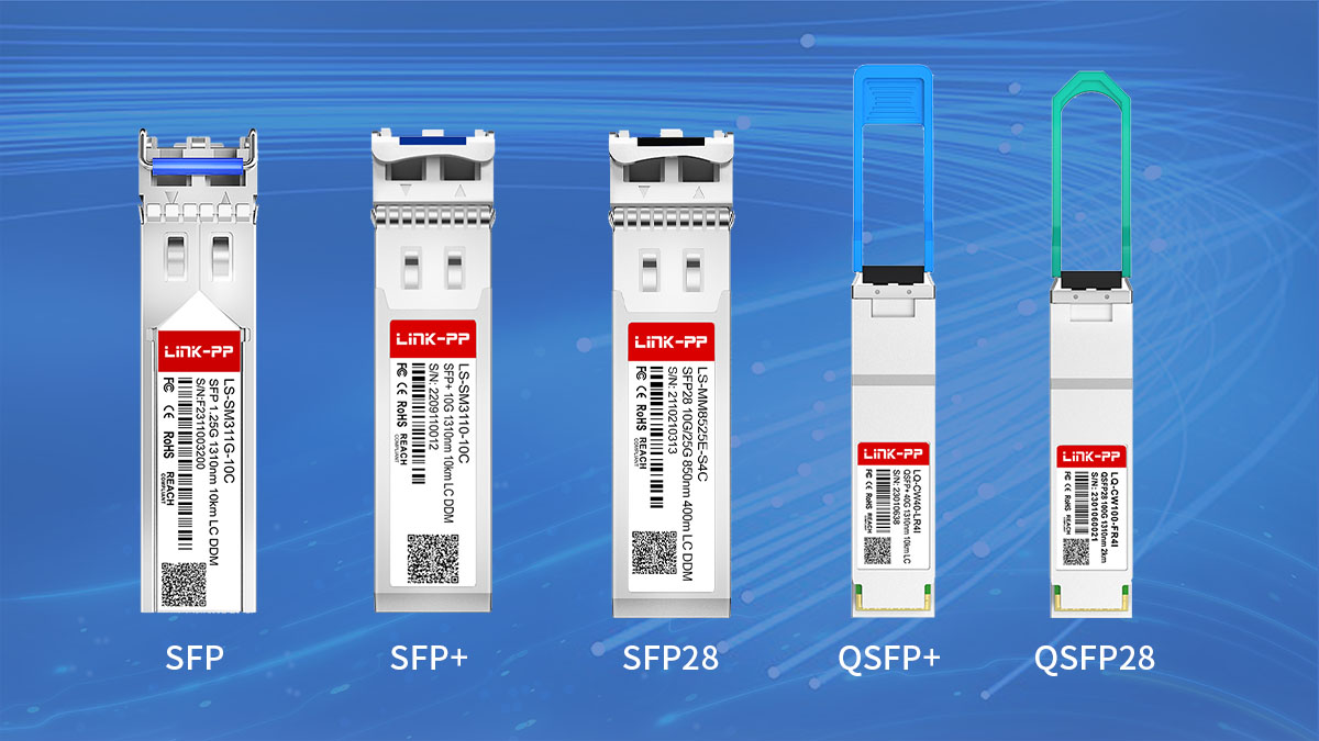
Common Transceiver Form Factors
Fiber optic transceivers are available in several standardized form factors that support different speeds and port densities. Each form factor is designed to match specific networking requirements.
| Form Factor |
Typical Data Rates |
Common Applications |
| SFP |
100M, 1G |
Access and legacy networks |
| SFP+ |
10G |
Enterprise and data center aggregation |
| SFP28 |
25G |
Server connectivity |
| QSFP+ |
40G |
Data center uplinks |
| QSFP28 |
100G |
Spine-leaf architectures |
| QSFP56 / QSFP-DD |
200G, 400G |
Hyperscale data centers |
Smaller form factors enable higher port density on switches, which is especially important in large-scale cloud infrastructure. For example, a single switch may support dozens of QSFP28 ports to provide high-bandwidth connectivity across a data center fabric.
Understanding the role, internal components, and physical formats of fiber optic transceivers provides the foundation for selecting the correct module for a given network environment. The next section explores the key technical factors that should guide the selection process.
? Key Factors to Consider When Selecting a Fiber Optic Transceiver
Selecting the correct fiber optical transceiver requires evaluating several technical parameters that directly affect network compatibility, link stability, and long-term scalability. The most important factors include data rate, transmission distance, fiber type, operating wavelength, and vendor compatibility. Understanding how these elements interact helps ensure that the chosen module aligns with both current infrastructure and future bandwidth requirements.
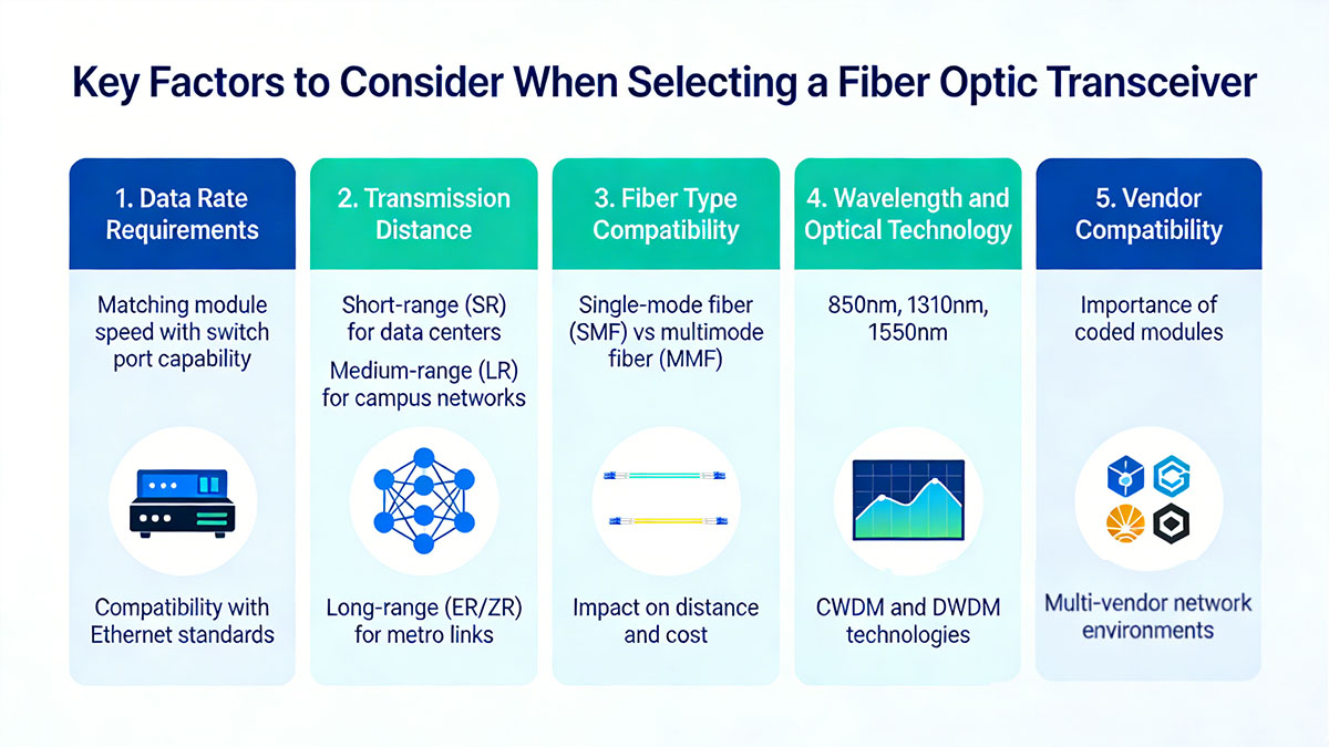
Data Rate Requirements
The first step in choosing a fiber optic transceiver is matching the module data rate with the supported port speed of the networking equipment. Optical modules are designed for specific Ethernet standards, and using an incorrect speed category may prevent the link from establishing properly.
The following table summarizes common fiber transceivers speeds and their typical form factors.
| Data Rate |
Common Form Factor |
Typical Network Layer |
| 100M |
SFP |
Legacy access networks |
| 1G |
SFP |
Enterprise access layer |
| 10G |
SFP+ |
Aggregation and server connectivity |
| 25G |
SFP28 |
Modern data center servers |
| 40G |
QSFP+ |
Data center uplinks |
| 100G |
QSFP28 |
Spine-leaf architectures |
| 200G / 400G |
QSFP56 / QSFP-DD |
Hyperscale data centers |
Higher speeds generally provide greater bandwidth efficiency, but they may also require newer switching platforms and different cabling infrastructure. When designing networks, many organizations consider both current traffic demand and expected growth before selecting a transceiver speed.
Transmission Distance
Transmission distance determines which optical standard should be used. Different fiber optic transceivers are designed for short-range, medium-range, or long-distance communication.
The following categories illustrate how distance typically influences module selection.
| Distance Category |
Typical Standards |
Common Applications |
| Short range |
SR optics |
Data center rack-to-rack connections |
| Medium range |
LR optics |
Campus network links |
| Long range |
ER / ZR optics |
Metropolitan or regional networks |
Short-range transceivers usually operate with multimode fiber and are optimized for data center environments where devices are located within the same facility. Long-range optics operate over single-mode fiber and support distances that can extend tens or even hundreds of kilometers.
Accurately estimating link distance before selecting a module helps prevent signal degradation and ensures stable network operation.
Fiber Type Compatibility
Fiber optic transceivers are designed to operate with either single-mode fiber or multimode fiber, and choosing the correct combination is essential for link functionality.
| Fiber Type |
Core Diameter |
Typical Distance Capability |
| Multimode fiber (MMF) |
50 or 62.5 microns |
Up to several hundred meters |
| Single-mode fiber (SMF) |
Approximately 9 microns |
Several kilometers to hundreds of kilometers |
Multimode fiber is commonly used in data centers due to its lower cost for short distances. Single-mode fiber supports longer transmission distances and is widely deployed in campus backbones, metropolitan networks, and telecommunications infrastructure.
Using the wrong fiber type for a transceiver can result in significant signal loss or a nonfunctional link.
Wavelength and Optical Technology
Optical transceivers operate at specific wavelengths that determine how signals propagate through fiber. The most common wavelengths are 850nm, 1310nm, and 1550nm.
| Wavelength |
Typical Module Types |
Typical Use Case |
| 850nm |
SR transceiver |
Short-range multimode links |
| 1310nm |
LR transceiver |
Medium-distance single-mode links |
| 1550nm |
ER / ZR transceiver |
Long-distance optical transport |
In addition to single-wavelength transmission, some modules use wavelength multiplexing technologies to increase bandwidth.
Examples include:
-
CWDM (Coarse Wavelength Division Multiplexing), which combines multiple wavelengths on a single fiber for moderate-distance links.
-
DWDM (Dense Wavelength Division Multiplexing), which supports a large number of closely spaced wavelengths for high-capacity optical transport systems.
These technologies are particularly important in metropolitan and carrier networks where fiber resources must be used efficiently.
Vendor Compatibility
Network equipment vendors often implement software checks that validate whether an optical module is supported by the platform. As a result, compatibility between transceivers and switches or routers is an important consideration.
| Compatibility Aspect |
Description |
| Vendor coding |
Modules are programmed to match specific equipment vendors |
| EEPROM identification |
Allows switches to recognize supported optics |
| Diagnostic monitoring |
Ensures accurate reporting of module parameters |
In multi-vendor environments, compatible optical modules can simplify deployment while maintaining interoperability. Ensuring that a module meets the electrical and optical requirements of the host equipment helps avoid link failures or unsupported hardware warnings.
Carefully evaluating these factors before deployment allows network designers to select fiber optic transceivers that deliver stable performance, appropriate transmission reach, and long-term scalability. The next section examines the different types of optical transceivers available across data rates ranging from 100M to 400G.
? Fiber Optic Transceiver Types by Data Rate
Fiber optical transceiver module is available in multiple speed categories to support different layers of modern networks. Each data rate corresponds to specific Ethernet standards, form factors, and deployment scenarios. Lower-speed modules are still widely used in legacy infrastructure, while higher-speed optics such as 100G, 200G, and 400G are designed for large-scale data center and cloud environments.
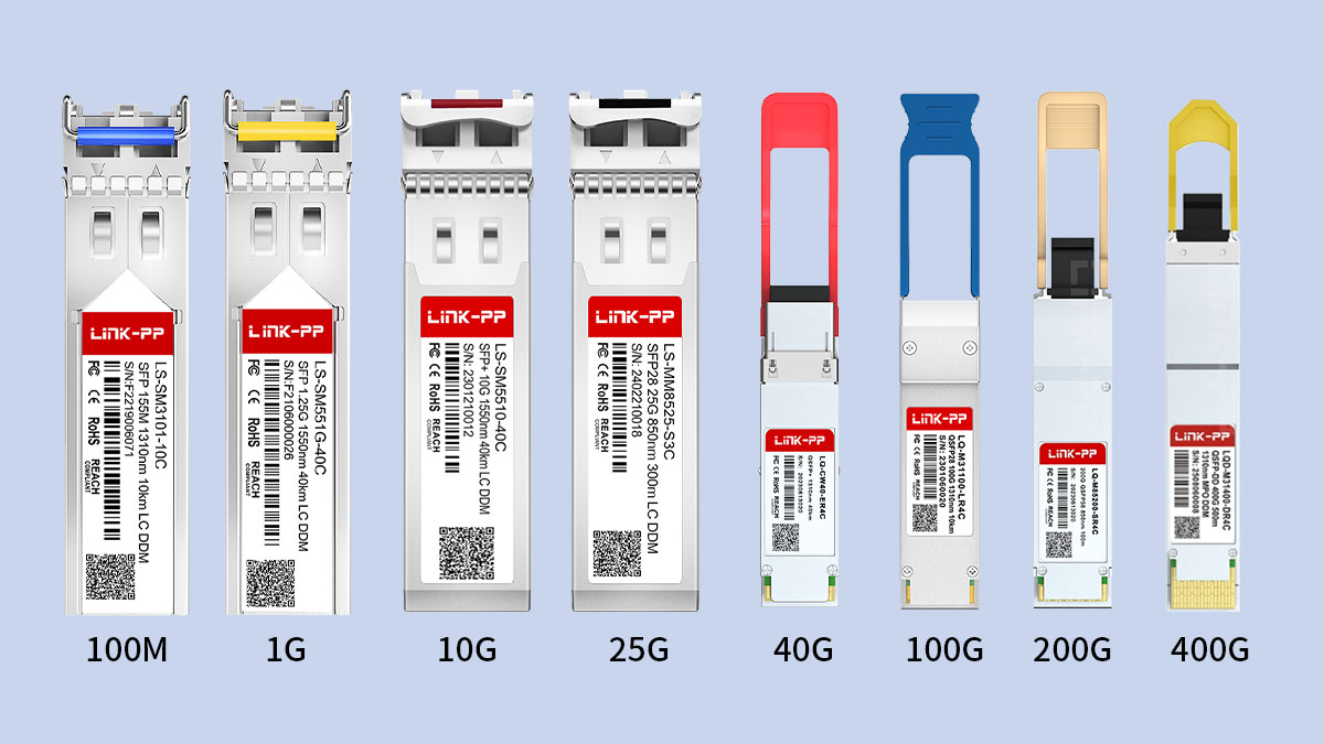
The following sections outline the characteristics and typical applications of fiber optic transceivers from 100M to 400G.
100M Fiber Optic Transceivers
100M SFP is commonly used in legacy networks where Fast Ethernet connectivity is still required. These modules typically follow the 100BASE-FX standard and are designed for simple, stable optical links over short to medium distances.
| Standard |
Form Factor |
Typical Distance |
| 100BASE-FX |
SFP |
Up to 2km |
| 100BASE-BX |
SFP |
Up to 20km |
| 100BASE-LX10 |
SFP |
Up to 10km |
These fast ethernet sfp is often deployed in industrial environments, campus networks, and legacy infrastructure where upgrading to higher speeds is not immediately necessary. Although newer technologies have largely replaced 100M links in modern data centers, they remain relevant for compatibility with older equipment.
1G Fiber Optic Transceivers
1G sfp module support Gigabit Ethernet and are widely deployed in enterprise networks and access-layer switching. They typically use the SFP form factor and support both multimode and single-mode fiber connections.
Gigabit sfp modules are commonly used for switch uplinks, campus backbone links, and network edge connectivity. Their broad compatibility and relatively low power consumption make them one of the most widely deployed optical module categories.
10G Fiber Optic Transceivers
10G sfp+ transceivers represent a major step forward in bandwidth and are widely used in both enterprise and data center environments. These modules typically use the SFP+ form factor and support several optical standards designed for different transmission distances.
10G optics are commonly deployed for server connectivity, aggregation layers, and inter-switch connections. The SFP+ form factor allows high port density while maintaining manageable power consumption in switching equipment.
25G Fiber Optic Transceivers
25G transceiver is designed to support higher server bandwidth requirements in modern data centers. They typically use the SFP28 form factor, which maintains the same physical size as SFP+ while supporting higher data throughput.
Because 25G provides 2.5 times the bandwidth of 10G while using similar cabling infrastructure, it has become a common choice for server-to-switch connectivity in high-performance data center networks.
40G Fiber Optic Transceivers
40G transceiver are typically used for data center aggregation and backbone connections. Most 40G modules use the QSFP+ form factor and transmit data across multiple parallel optical channels.
Parallel optical transmission allows multiple lanes to operate simultaneously, enabling higher throughput without significantly increasing individual lane speeds. These modules are often used for switch uplinks or high-capacity network segments.
100G Fiber Optic Transceivers
100G module have become a standard choice for high-performance data center networks and large enterprise infrastructures. Most 100G modules use the QSFP28 form factor and support multiple optical transmission technologies.
These modules are frequently deployed in spine-leaf architectures where high bandwidth and low latency are required for east-west traffic within data centers.
200G Fiber Optic Transceivers
200G optical transceiver is designed to increase bandwidth capacity while maintaining efficient power usage and port density. They commonly use the QSFP56 form factor and support several high-speed optical standards.
| Standard |
Connector Type |
Typical Distance |
| 200GBASE-SR4 |
MPO |
Up to 100m |
| 200GBASE-DR4 |
MPO |
Up to 500m |
| 200GBASE-FR4 |
LC |
Up to 2km |
These modules are commonly deployed in next-generation data center switching platforms that require higher throughput between aggregation and core layers.
400G Fiber Optic Transceivers
400G optical transceiver represent the current generation of high-speed optical connectivity used in hyperscale cloud infrastructure and large data center fabrics. These modules typically use QSFP-DD or OSFP form factors.
| Standard |
Connector Type |
Typical Distance |
| 400GBASE-SR8 |
MPO |
Up to 100m |
| 400GBASE-DR4 |
MPO |
Up to 500m |
| 400GBASE-FR4 |
LC |
Up to 2km |
By combining multiple high-speed optical lanes and advanced modulation techniques, 400G transceiver significantly increase network capacity while maintaining manageable power and thermal characteristics.
Understanding the different data rate categories helps network planners determine which fiber optic transceiver types best match the performance requirements of a specific network architecture. The next section explores how fiber types and optical connectors further influence transceiver selection.
? Fiber Type and Connector Selection
Selecting the correct fiber type and optical connector is essential for ensuring that a fiber optic transceiver operates reliably within a network link. The choice typically depends on transmission distance, module type, and the physical interface used by the optical transceiver. In most deployments, the decision comes down to two key aspects: whether the network uses multimode or single-mode fiber, and whether the connection requires duplex or parallel optical interfaces.
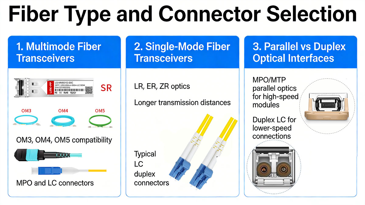
Multimode Fiber Transceivers
Multimode fiber transceivers are designed for short-distance communication and are commonly used inside data centers where network devices are located within the same facility. These modules typically operate at an 850nm wavelength and are optimized for high-speed transmission over multimode fiber types such as OM3, OM4, or OM5.
The typical characteristics of multimode fiber deployments are summarized below.
| Fiber Standard |
Core Diameter |
Typical Distance (10G SR) |
| OM2 |
50µm |
Up to 82m |
| OM3 |
50µm |
Up to 300m |
| OM4 |
50µm |
Up to 400m |
| OM5 |
50µm |
Up to 400m+ |
Multimode fiber is often preferred for short-range links because the transceivers and cabling infrastructure are generally more cost-efficient. It is widely used for rack-to-rack connections, server access layers, and high-density switching environments.
However, multimode fiber is limited in transmission distance compared to single-mode fiber, which is why it is primarily deployed in controlled environments such as data centers.
Single-Mode Fiber Transceivers
Single-mode fiber transceivers are designed for longer transmission distances and are commonly used in campus, metropolitan, and carrier networks. These modules typically operate at wavelengths such as 1310nm or 1550nm and can support transmission ranges from several kilometers to over 80km depending on the optical standard.
The following table outlines typical single-mode optical standards and their transmission ranges.
| Optical Standard |
Typical Wavelength |
Typical Distance |
| LR |
1310nm |
Up to 10km |
| ER |
1550nm |
Up to 40km |
| ZR |
1550nm |
Up to 80km |
Single-mode fiber has a much smaller core diameter than multimode fiber, allowing light signals to travel longer distances with less modal dispersion. This characteristic makes it suitable for backbone networks, inter-building connections, and long-distance data transmission.
Many organizations deploy single-mode fiber even for shorter links when future scalability and network expansion are important considerations.
Parallel vs Duplex Optical Interfaces
In addition to fiber type, the optical connector interface also plays a major role in fiber optic transceiver selection. Different connector types support different optical transmission architectures.
| Interface Type |
Connector Type |
Typical Module Types |
| Duplex optical |
LC duplex |
SFP, SFP+, SFP28 |
| Parallel optical |
MPO/MTP |
QSFP+, QSFP28, QSFP-DD |
| Bi-directional |
LC simplex |
BiDi modules |
Duplex optical connections use two fiber strands—one for transmitting and one for receiving signals. This design is common in lower-speed modules such as 1G, 10G, and many 25G or 100G LR optics.
Parallel optical connections use multi-fiber connectors such as MPO or MTP. These connectors allow multiple optical lanes to operate simultaneously, which is required for higher-speed modules such as 40G SR4 or 100G SR4.
Bidirectional sfp use wavelength division technology to transmit and receive signals on a single fiber strand, which can reduce the amount of fiber infrastructure required in certain deployments.
Understanding how fiber types and connector interfaces interact with optical modules helps ensure that network links are correctly designed and capable of supporting the required data rates and transmission distances. The next section examines how different transceiver speeds are deployed across various network environments.
? Deployment Scenarios for Different Transceiver Speeds
Different fiber optic transceiver speeds are typically deployed at specific layers of network architecture. The selection depends on factors such as bandwidth demand, traffic patterns, and infrastructure scale. Lower-speed modules often appear at access layers or in legacy systems, while higher-speed optics support aggregation, core networking, and large-scale data center fabrics.
Understanding where each speed category is commonly used helps network planners align optical module selection with real deployment requirements.
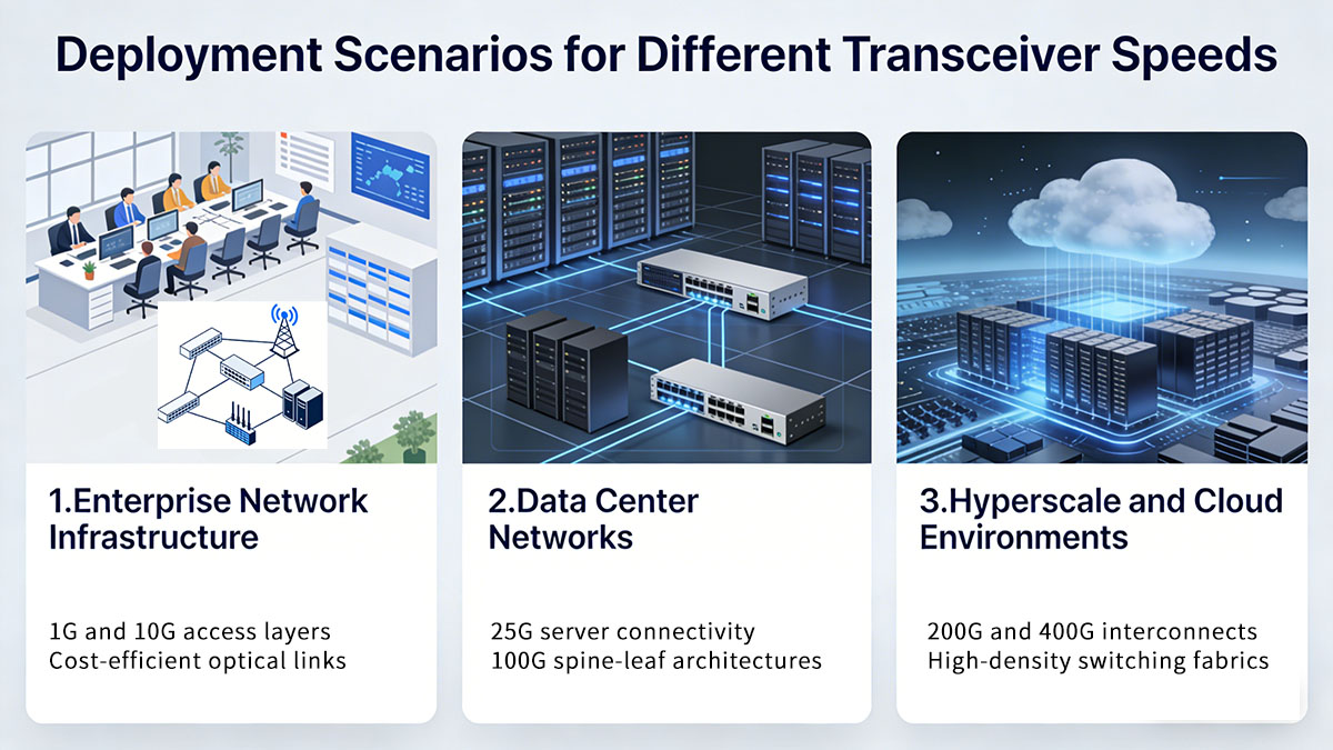
Enterprise Network Infrastructure
In enterprise environments, fiber optic transceivers are commonly used to connect access switches, aggregation layers, and campus backbone links. These networks usually prioritize stability, compatibility with existing infrastructure, and moderate bandwidth requirements.
The following table summarizes typical transceiver speeds used in enterprise networks.
| Network Layer |
Common Speeds |
Typical Use Case |
| Access layer |
1G, 10G |
User access switches and edge connectivity |
| Aggregation layer |
10G, 25G |
Inter-switch links within buildings |
| Campus backbone |
10G, 40G |
Building-to-building connections |
1G and 10G transceivers remain widely deployed in enterprise access networks because they provide sufficient bandwidth for typical office workloads such as file sharing, collaboration platforms, and internal applications. For larger campuses, 40G uplinks may be used to increase backbone capacity between distribution switches.
Enterprise networks often deploy single-mode transceivers for campus backbones, as they provide greater flexibility for longer-distance connections across multiple buildings.
Data Center Networks
Modern data centers rely heavily on fiber optic transceivers to support large volumes of east–west traffic between servers, storage systems, and network switches. High-speed optical transceiver is commonly used to maximize bandwidth efficiency and port density.
Typical data center deployments are structured around leaf-spine architectures.
| Network Segment |
Common Speeds |
Typical Connection |
| Server access |
10G, 25G |
Server NIC to leaf switch |
| Leaf to spine |
40G, 100G |
Aggregation within the data center fabric |
| Storage networks |
25G, 100G |
High-throughput storage traffic |
25G transceivers have become particularly common for server connectivity because they provide higher throughput than 10G while maintaining similar cabling infrastructure. Meanwhile, 100G transceivers are widely used for spine connections where multiple leaf switches must exchange large amounts of traffic.
Multimode SR transceivers are frequently used inside data centers due to their suitability for short-range connections between racks.
Hyperscale and Cloud Environments
Hyperscale cloud providers operate extremely large data center infrastructures where network capacity must scale rapidly. In these environments, high-speed fiber optic transceivers such as 100G, 200G, and 400G are used extensively to support massive east–west traffic and distributed computing workloads.
The table below illustrates typical deployment speeds in hyperscale environments.
| Network Layer |
Common Speeds |
Typical Role |
| Server access |
25G, 50G |
High-bandwidth compute nodes |
| Aggregation layer |
100G |
Interconnection between leaf switches |
| Core fabric |
200G, 400G |
Large-scale data center backbone |
400G optical module is increasingly deployed in core switching fabrics to support extremely high throughput between large clusters of servers. These high-speed links help reduce network congestion and enable scalable architectures for cloud computing, artificial intelligence workloads, and distributed storage systems.
In hyperscale deployments, high-density form factors such as QSFP-DD transceiver allow switches to support dozens of high-speed ports, significantly increasing overall switching capacity while maintaining manageable power consumption.
Understanding these deployment patterns helps clarify how different fiber optic transceiver speeds align with real-world network architectures. The next section examines compatibility and interoperability considerations when deploying optical modules across different networking platforms.
? Compatibility and Interoperability Considerations
Ensuring compatibility and interoperability is an essential step when deploying fiber optic transceivers in a network. Even when modules share the same form factor and optical specifications, differences in vendor implementation, firmware checks, or hardware requirements can affect whether a link operates correctly. Careful attention to compatibility helps avoid unsupported hardware warnings, unstable links, or failed connections.
In most environments, compatibility considerations fall into three areas: vendor-specific coding, compliance with technical standards, and interoperability validation across different devices.
Vendor-Specific Coding
Many networking equipment manufacturers implement identification checks that verify whether an inserted optical module is supported by the device. These checks rely on information stored in the transceiver’s EEPROM, which contains details such as vendor name, model number, and operational parameters.
The following table summarizes common aspects of vendor-specific coding.
| Coding Aspect |
Description |
Purpose |
| EEPROM identification |
Stores vendor and module information |
Allows devices to recognize supported modules |
| Vendor ID field |
Identifies the original manufacturer |
Ensures compatibility with host equipment |
| Firmware validation |
Performed by switches or routers |
Prevents unsupported modules from operating |
If the module information does not match the expected vendor profile, some devices may display compatibility warnings or disable the interface. For this reason, modules used in enterprise or data center equipment are often coded to match specific vendor platforms.
In multi-vendor networks, using properly coded compatible modules helps maintain flexibility while ensuring that switches and routers correctly recognize the installed optics.
Standards Compliance
Beyond vendor coding, optical transceivers must comply with widely recognized industry standards to ensure reliable operation across networking equipment. These standards define the electrical interfaces, optical characteristics, and physical dimensions of the modules.
The table below outlines the main standards that govern fiber optic transceivers.
| Standard Organization |
Scope |
Example Standards |
| IEEE |
Ethernet transmission standards |
1000BASE-LX, 10GBASE-SR |
| MSA (Multi-Source Agreement) |
Form factor specifications |
SFP+, QSFP28 |
| ITU-T |
Optical transport standards |
DWDM systems |
Compliance with these standards ensures that modules meet the required optical power levels, wavelengths, and signal integrity specifications. This makes it possible for equipment from different manufacturers to communicate over standardized optical links.
For example, a SFP+ LR transceiver that meets IEEE specifications should function correctly with any compatible 10G LR interface that follows the same standard.
Interoperability Testing
Even when modules meet the same standards, practical interoperability testing is still important to confirm stable operation in real-world deployments. Differences in firmware versions, switch configurations, or environmental conditions can sometimes affect link behavior.
Typical interoperability validation includes the following checks:
-
Verifying that the switch correctly recognizes the transceiver
-
Confirming that the optical link establishes successfully
-
Checking transmit and receive optical power levels
-
Monitoring error counters and link stability
Network administrators often use diagnostic tools or built-in monitoring features to verify these parameters after installation. Many modern optical modules support digital diagnostics monitoring, which provides real-time information about temperature, voltage, and optical power levels.
By ensuring compatibility at both the hardware and standards levels, organizations can deploy fiber optic transceivers across complex networks with greater confidence. The next section explores how optical transceiver technologies are evolving to support future network bandwidth demands.
? Future Trends in Fiber Optic Transceiver Technology
Fiber optic transceiver technology continues to evolve as global network traffic grows and data center architectures demand higher bandwidth, lower latency, and greater efficiency. The industry is moving toward higher transmission speeds, increased port density, and improved energy efficiency to support modern cloud computing, artificial intelligence workloads, and large-scale digital services.
Understanding these trends helps network planners anticipate how optical infrastructure may evolve in the coming years.
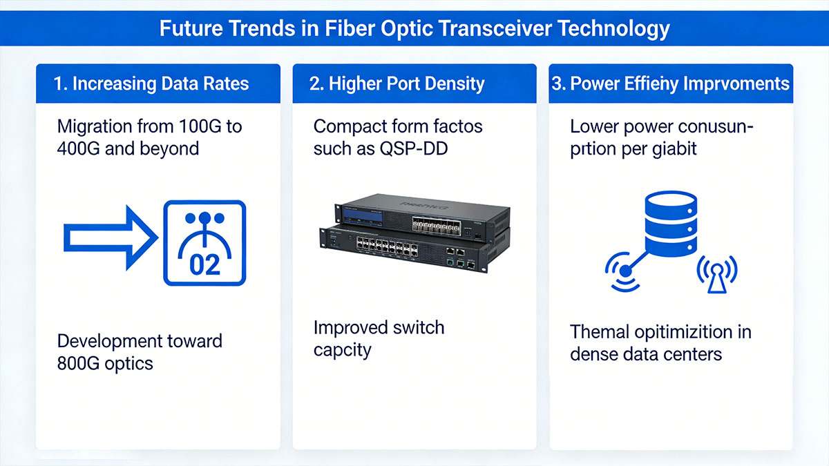
Increasing Data Rates
One of the most significant trends in optical networking is the continuous increase in transmission speeds. As applications generate more data and real-time processing requirements grow, network infrastructure must support higher throughput without significantly increasing physical footprint.
The following table outlines the general progression of optical transceiver speeds in modern networks.
| Generation |
Typical Data Rate |
Primary Deployment Period |
| Early data center optics |
10G |
2010s |
| High-density data center optics |
25G / 40G |
Mid–late 2010s |
| Cloud-scale networking |
100G |
Late 2010s–present |
| Next-generation infrastructure |
200G / 400G |
Current deployments |
Higher data rates allow fewer physical links to carry larger volumes of traffic. For example, upgrading from 100G to 400G reduces the number of optical connections needed to achieve the same aggregate bandwidth.
Research and development efforts are already moving toward 800G and beyond, which will further increase network capacity in large-scale computing environments.
Higher Port Density
As network bandwidth increases, switch manufacturers must support more high-speed ports within the same hardware footprint. This requirement has led to the development of compact optical transceiver form factors designed for high-density deployments.
| Form Factor |
Typical Speeds |
Key Advantage |
| SFP+ |
10G |
Compact design for access networks |
| QSFP28 |
100G |
High-density 100G switching |
| QSFP56 |
200G |
Increased bandwidth per port |
| QSFP-DD |
400G |
Double-density port architecture |
High-density modules enable network switches to support a larger number of high-speed links while maintaining manageable power and thermal characteristics. This is particularly important in hyperscale data centers where thousands of servers must communicate simultaneously.
By increasing the bandwidth available per switch port, these form factors allow network operators to scale infrastructure without dramatically expanding rack space or hardware complexity.
Power Efficiency Improvements
Power consumption has become a critical consideration as data centers grow in size and network speeds continue to rise. Optical transceiver manufacturers are increasingly focusing on improving energy efficiency while maintaining high performance.
Several technological developments are contributing to these improvements:
-
Advanced optical modulation techniques that transmit more data per wavelength
-
Improved semiconductor manufacturing processes for lower power consumption
-
Enhanced thermal management designs within high-speed modules
-
Integration of more efficient digital signal processing components
Lower power consumption per gigabit of bandwidth helps reduce operational costs and supports sustainability goals in large data center environments. As transmission speeds increase toward 800G and future terabit-scale optics, power efficiency will remain a central focus of optical transceiver innovation.
Together, these trends indicate that fiber optic transceivers will continue to play a fundamental role in enabling scalable, high-performance network infrastructure. The final section addresses common questions about optical transceivers and their deployment in modern networks.
? Conclusion
Fiber optic transceivers play a central role in enabling modern network connectivity, supporting data transmission across a wide range of speeds from 100M legacy infrastructure to high-capacity 400G data center networks. By converting electrical signals into optical signals, these modules allow network equipment to communicate efficiently over fiber while maintaining high bandwidth, long transmission distances, and low signal loss.
Selecting the appropriate fiber optic transceiver requires careful consideration of several factors, including data rate requirements, transmission distance, fiber type, optical wavelength, connector interface, and device compatibility. Understanding how these parameters interact helps ensure that network links operate reliably and remain scalable as bandwidth demands increase. Different speed categories—such as 1G and 10G for enterprise networks, 25G and 100G for data centers, and 200G or 400G for hyperscale environments—serve distinct roles within modern network architectures.
As optical networking technologies continue to evolve, higher transmission speeds, improved port density, and greater power efficiency will shape the next generation of fiber optic transceivers. Organizations planning network upgrades or new deployments can benefit from evaluating both current infrastructure needs and future scalability when selecting optical modules.
For organizations seeking reliable optical connectivity solutions across multiple speed categories, the LINK-PP Official Store provides a comprehensive range of fiber optic transceivers designed to support diverse network environments. Exploring available module options can help identify transceiver specifications that align with specific infrastructure requirements and long-term network development plans.


