
As enterprise and telecom networks continue to scale, balancing high performance with cost-effective infrastructure remains a top priority. The FCLF-8521-3 Finisar 1000BASE-T Copper SFP transceiver has emerged as a reliable data center workhorse, offering a seamless bridge between optical routing and traditional copper setups. By converting standard SFP slots into 1G copper interfaces, this module allows network operators to maximize their existing hardware investments without a complete fiber overhaul.
Designed for high-density environments, the FCLF-8521-3 delivers reliable 1000 Mbps data rates over standard Category 5/5e/6 cabling up to 100m. This makes it an ideal solution for critical applications ranging from enterprise switching fabrics to telecom edge networks. In this comprehensive guide, we will dive deep into its core technical specs, host compatibility, and best troubleshooting practices to help you optimize your network's physical layer.
📝 Introduction to the FCLF-8521-3 Finisar Copper SFP
The FCLF-8521-3 is a highly versatile SFP transceiver module engineered to deliver seamless Gigabit Ethernet connectivity over standard copper cabling. By plugging directly into existing SFP ports, it effortlessly bridges the gap between legacy hardware and modern, high-speed switch architectures. Ultimately, this reliable Finisar module serves as an essential, go-to solution for network operators looking to optimize their infrastructure worldwide.
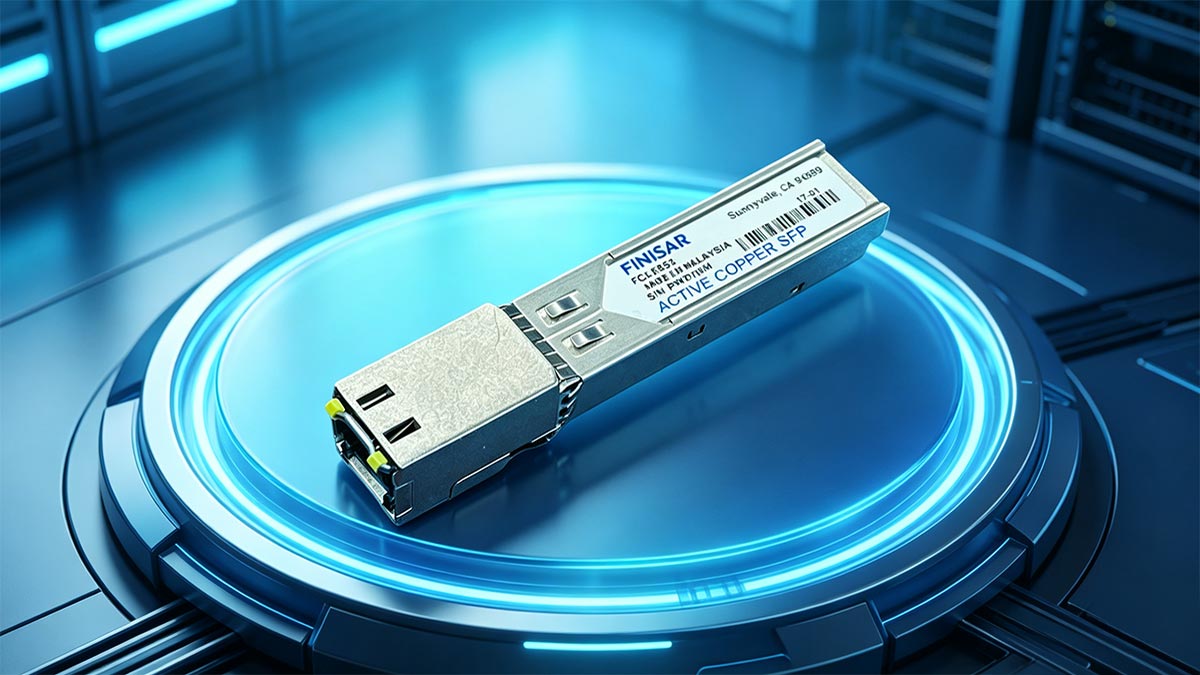
Overview of the Finisar FCLF-8521-3
The Finisar FCLF-8521-3 stands out as a highly adaptable 10/100/1000BASE-T copper SFP transceiver, meaning it can automatically sense and adjust to speeds of 10Mbps, 100Mbps, or 1Gbps. Unlike optical modules that depend on fiber optic cables, this module features a built-in RJ45 connector designed for standard copper patch cords. Because it is fully hot-pluggable, network administrators can insert or remove it from an active switch port on the fly without causing system downtime or needing to reboot the host hardware.
This triple-speed capability allows the transceiver to act as a universal bridge within any mixed-generation network environment. By converting a standard SFP slot into a flexible copper port, it seamlessly handles everything from legacy Fast Ethernet links to modern high-speed Gigabit connections. It provides the physical stability and plug-and-play simplicity required to run high-density network layouts smoothly and cost-effectively.
Key Target Applications in Enterprise and Telecom Networks
In enterprise environments, this module is frequently used to connect top-of-rack switches directly to servers and storage area networks (SANs) across short distances. It leverages the existing Cat5e or Cat6 copper infrastructure already installed in most corporate buildings, eliminating the need for expensive fiber upgrades.
For telecom operators, the transceiver serves as a rugged interface point at the network edge, linking broadband access platforms to central IP networks. Its built-in auto-negotiation feature ensures that older legacy devices and modern high-speed switches can communicate perfectly on the same network.
Why the FCLF-8521-3 is a Data Center Workhorse
Data centers require dependable, high-density hardware that keeps running costs low, which is exactly why the FCLF-8521-3 is widely considered an industry workhorse. It gives IT managers the flexibility to immediately convert an unused fiber SFP port into a copper connection whenever server demands change.
Furthermore, this transceiver is designed with low power consumption and efficient heat dissipation in mind. Its robust physical construction minimizes hardware failures, helping data centers maintain continuous uptime while reducing overall equipment maintenance costs.
Understanding the Shift from Optical to 1G Copper Interfaces
While fiber optic cables are necessary for long-distance data transmission, short connections within a local rack or server room often shift to copper to cut down on expensive fiber patch panels and optical modules. Choosing a copper interface provides a highly practical, cost-effective alternative for localized networking.
The following table highlights the operational and structural differences between a standard 1G Fiber SFP and the FCLF-8521-3 Copper SFP:
| Feature |
1G Fiber SFP |
1G Copper SFP (FCLF-8521-3) |
| Media Type |
Fiber Optic Cable |
Category 5 / 5e / 6 Copper Cable |
| Connector Type |
LC or SC |
RJ45 |
| Max Distance |
Up to 550m (MMF) or 10km+ (SMF) |
Up to 100m |
| Power Consumption |
Typically lower |
Slightly higher |
| Primary Use Case |
Long-haul or backbone links |
Short-range rack patching & edge access |
📝 Core Technical Specifications of the FCLF-8521-3 Module
Evaluating the core technical benchmarks of the FCLF-8521-3 is essential for ensuring stable, deterministic performance across a corporate network footprint. This module integrates high-speed digital physical layer (PHY) circuitry with low-power components to maintain optimal efficiency under heavy traffic loads. The engineering metrics detailed below outline the structural and operational parameters that define this transceiver.
Data Rate and Power Consumption Metrics
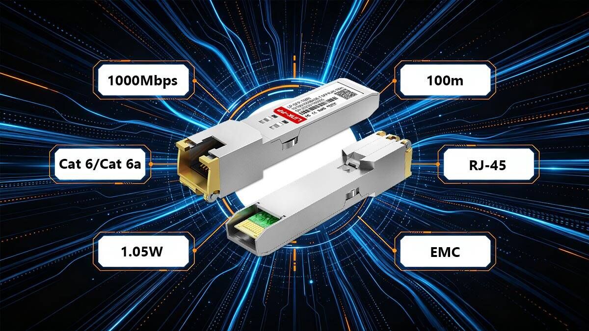
The FCLF-8521-3 delivers a robust line rate of 1Gbps, supporting full-duplex bi-directional data transfers with zero packet degradation. It manages this throughput while maintaining a highly efficient power profile, typically drawing around 1.05W of power under maximum load conditions. This low power consumption is crucial for minimizing the overall thermal footprint when multiple modules are packed into a single switch.
To protect the host switch from sudden electrical spikes, the module is engineered with a low-voltage power supply architecture operating at 3.3V. This optimized power usage helps prevent localized hot spots on the network line card, which extends the lifespan of both the transceiver and the host equipment. It ensures that deploying several copper ports simultaneously will not strain the switch's power supply budget.
IEEE 802.3ab 1000BASE-T Compliance Standards
Full compliance with the IEEE 802.3ab standard ensures that the FCLF-8521-3 operates seamlessly across any multi-vendor networking environment. This certification guarantees that the transceiver properly executes physical layer requirements, including mandatory 5-level Pulse Amplitude Modulation (PAM-5) encoding over copper lines. It allows the module to communicate flawlessly with any other IEEE-compliant network interface card (NIC) or router port.
Beyond basic encoding, this standard enforces advanced hardware auto-negotiation protocols directly through the twisted-pair medium. The module automatically syncs speed, duplex settings, and master/slave clock configurations without needing manual software overrides from network administrators. This strict adherence to global networking benchmarks guarantees immediate plug-and-play interoperability.
Form Factor and Mechanical Dimensions
Built to conform strictly to the international Small Form-factor Pluggable (SFP) Multi-Source Agreement (MSA), the module boasts a compact, uniform footprint. The housing is explicitly shaped to slide smoothly into standard SFP cages, maximizing port density along the front panel of enterprise switches. It features an integrated bale-clasp extraction mechanism that allows for easy locking and release during rapid installations.
The mechanical design also includes an exposed, integrated RJ45 female connector port that stands flush with the switch faceplate when fully inserted. The external metal spring fingers around the transceiver body provide robust grounding points against the host cage, which significantly cuts down on structural wobble. This precise fit protects the delicate internal physical connections from everyday operational vibrations.
📝 Electrical Interface and Pin Configuration of FCLF-8521-3
Understanding the electrical interface of the FCLF-8521-3 is essential for ensuring hardware stability and seamless communication with the host system. This module connects to the host board through a standardized physical interface that handles power delivery, high-speed data transfer, and low-speed control tracking. The following breakdown outlines how the transceiver manages its electrical layout to maintain steady, interference-free performance.

20-Pin MSA Connector Layout Breakdown
The FCLF-8521-3 utilizes a standard 20-pin electrical connector defined by the SFP Multi-Source Agreement (MSA) to interface with the host switch card. This layout includes dedicated pins for high-speed differential data lines, consisting of two transmit pins (TD+ and TD-) and two receive pins (RD+ and RD-). These pairs handle the high-bandwidth serialized data flowing between the host switch and the module's internal PHY chip.
The remaining pins on the 20-pin connector are dedicated to system grounding, low-speed controls, and a two-wire serial management interface. Proper alignment and contact pressure on these pins ensure that data signals remain clean and uninterrupted during continuous network operations. This uniform layout guarantees that the module fits into any MSA-compliant edge connector without compatibility worries.
Low-Speed Signaling and Control Pins
Beyond high-speed data paths, the FCLF-8521-3 relies on low-speed control pins to communicate its operational status to the host switch. Key pins like TX_Fault, TX_Disable, and MOD_DEF(0,1,2) allow the host system to monitor transceiver presence and manage port initialization dynamically. For example, pulling the TX_Disable pin high allows the switch to shut down the transceiver's transmitter remotely for security or power-saving purposes.
The module also uses the MOD_DEF serial clock and data pins to let the host switch read its internal EEPROM data. This two-wire serial interface allows the switch to instantly identify the transceiver model, manufacturer info, and basic configuration details. This background communication ensures the system automatically configures the correct interface parameters as soon as the module is inserted.
Power Supply Noise Filtering Requirements
Because copper SFP transceivers pack sensitive digital circuitry into a small space, they require an electrically quiet power environment to avoid performance issues. The host switch must provide a stable 3.3V power supply that is carefully conditioned using an external noise filtering network. This network typically uses a combination of inductors and capacitors placed right next to the SFP host connector slot.
Without adequate filtering, high-frequency voltage ripples from the switch's power supply can leak into the transceiver's internal circuits. This noise can degrade signal integrity on the copper cable lines, leading to intermittent packet drops or link flapping. Adhering to Finisar’s recommended power supply filtering layout keeps the internal components running smoothly and ensures maximum signal stability.
Surge Protection and ESD Defenses
Operating in dense enterprise networks exposes transceivers to potential hazards like electrostatic discharge (ESD) and sudden electrical surges. The FCLF-8521-3 is engineered with built-in ESD protection circuitry that safeguards its sensitive internal pins during hot-swapping or cable connection. This protective shielding actively diverts harmful static voltage spikes safely away from the delicate processing chips.
Additionally, the integrated RJ45 port features isolated magnetics that provide robust electrical isolation between the copper network cable and the host switch. This built-in barrier blocks common-mode voltage surges and ground loops that can occur across long cable runs. These combined defenses greatly reduce the risk of hardware damage, ensuring long-term operational reliability in unpredictable electrical environments.
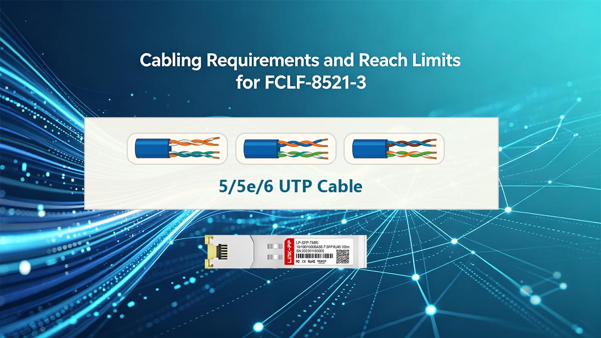
📝 Cabling Requirements and Reach Limits for FCLF-8521-3
Deploying the FCLF-8521-3 successfully depends heavily on adhering to proper copper cabling standards and distance limitations. While copper media offers unmatched flexibility and cost savings for localized connections, it is subject to physical constraints that fiber optics do not face. Understanding these cabling parameters ensures optimal signal integrity and prevents unexpected packet drops across your network links.
Category 5/5e/6 UTP Cable Compatibility
The FCLF-8521-3 is engineered to operate seamlessly over standard Unshielded Twisted Pair (UTP) copper infrastructure. It offers broad backward compatibility, working efficiently with older Category 5 cables, as well as modern Category 5e and Category 6 variants. For true Gigabit Ethernet performance, Category 5e or higher is highly recommended to satisfy the rigorous signaling requirements of the 1000BASE-T standard.
Using higher-grade cables like Cat6 or Cat6A provides better internal physical separation of the copper pairs, which naturally lowers signal degradation. This makes the transceiver incredibly versatile, allowing network operators to utilize existing patch panels without replacing massive amounts of legacy building wiring.
Maximum Link Distance and Performance at 100 Meters
In strict accordance with the IEEE 802.3ab standard, the maximum physical reach for the FCLF-8521-3 over copper cabling is exactly 100m. This distance limit represents the combined length of the permanent horizontal link and any patch cords used on either end. Exceeding this 100-meter threshold causes severe attenuation, preventing the transceiver from maintaining a stable gigabit connection.
When operating near the maximum distance limit, the quality of the cable installation becomes critical for performance. Any sharp bends, tight cable ties, or poor-quality patches can shorten the effective reliable distance of the link. Keeping cable runs well within the 100-meter limit ensures maximum data throughput and predictable baseline latency.
RJ45 Connector Termination Best Practices
The physical connection to the FCLF-8521-3 relies entirely on its integrated RJ45 female port, making precise cable termination vital. Installers should always use high-quality RJ45 plugs and ensure that the copper wire twists are maintained as close to the termination point as possible. Excessive untwisting of the wires during crimping is a leading cause of localized signal loss and performance degradation.
Additionally, checking for a secure, click-in lock when plugging the RJ45 connector into the copper transceiver ensures continuous physical contact. Loose connections can lead to intermittent link flapping, where the switch repeatedly loses and gains its physical layer link. Standardizing on the T568B wiring scheme across all patch cords helps maintain uniform pin mapping throughout the facility.
Mitigating Crosstalk and Electromagnetic Interference
Copper networking cables are inherently vulnerable to electromagnetic interference (EMI) and crosstalk from neighboring data or power lines. The FCLF-8521-3 mitigates this by using internal digital signal processing to cancel out echo and near-end crosstalk (NEXT) at the hardware level. However, installers must still maintain physical separation between high-voltage power conduits and network data bundles to avoid external signal disruptions.
To achieve clean transmission, specific deployment strategies must be used alongside the module's built-in defenses to shield data streams from environmental noise.
The table below outlines the primary types of interference and the best operational methods to control them:
| Interference Type |
Root Cause |
Mitigation Strategy |
| Near-End Crosstalk (NEXT) |
Signal bleeding between adjacent wire pairs inside the same RJ45 plug. |
Use Cat6 rated connectors and maintain wire twists up to the crimp. |
| Alien Crosstalk (ANEXT) |
Electromagnetic noise leaking from tightly bundled parallel cable runs. |
Avoid tight zip-ties; use loose hook-and-loop straps or utilize Cat6A cabling. |
| External EMI / RFI |
Proximity to fluorescent lights, electric motors, or power lines. |
Keep data paths at least 5 inches away from high-voltage electrical conduits. |
| Chassis Noise |
Electrical ground ripples from the host switch cage. |
Ensure the transceiver's metal grounding fingers fit snugly in the SFP slot. |
📝 Monitoring and Diagnostics Limitations of FCLF-8521-3
Managing a network requires clear visibility into system health, but copper transceivers operate differently from their optical counterparts. The FCLF-8521-3 does not feature traditional digital diagnostic tools, which means network engineers must adjust their monitoring workflows. Understanding these specific limitations helps administrators choose alternative methods to keep track of physical layer performance.

Why Copper SFPs Do Not Support Digital Optical Monitoring
Digital Optical Monitoring (DOM) — also known as Digital Diagnostic Monitoring (DDM) — relies on built-in laser sensors to measure internal optical metrics. Because the FCLF-8521-3 passes electrical signals over twisted-pair copper wire instead of light waves through glass, it completely lacks components like laser diodes or photo-receivers. Consequently, traditional real-time metrics such as optical transmit power, receive power, and laser bias current simply do not exist for this module.
Furthermore, standard SFP multi-source agreements do not map out a universal way to report copper-specific analog metrics through the standard DOM memory address space. Instead of searching for non-existent laser diagnostics, the host system reads basic configuration bytes from the module's EEPROM. This architectural difference requires network operators to look to the switch operating system for physical link troubleshooting data rather than relying on DOM software alerts.
Alternative Link Status and Loss of Signal Tracking
Even without DOM data, the FCLF-8521-3 communicates vital operational health metrics to the host switch via hardware pin signaling and register polling. It relies heavily on standard link pulses to confirm whether a physical partner is connected at the other end of the wire. The host switch uses this immediate hardware loop to update the interface status as "up" or "down" inside the Command Line Interface (CLI).
Loss of Signal (LOS) monitoring on this copper SFP is managed directly by the module's internal physical layer (PHY) chip. When the transceiver stops receiving valid electrical pulses from the connected cable, it updates its internal registers to alert the host system. This allows network management software to trigger immediate alerts and log localized port events just as quickly as it would with an optical network connection.
Host-Side Cable Diagnostics and PHY Register Access
To make up for the absence of DOM data, advanced network administrators can tap directly into the internal PHY registers of the FCLF-8521-3 via the switch operating system. This access uses the standard Management Data Input/Output (MDIO) serial interface to read real-time register states. These registers hold highly detailed data regarding local hardware operation, including negotiation status and line quality indicators.
Many modern enterprise switches can also run host-side Time Domain Reflectometry (TDR) cable diagnostics through this register interface. When activated, the system sends an electrical test pulse down the connected copper wire to map the physical state of the link. This allows the switch to detect severe wiring faults, pinpoint cable breaks, and estimate the exact distance to an electrical short-circuit without needing external testing tools.
Troubleshooting Layer 1 Link Failures Without DDM Data
When a port utilizing an FCLF-8521-3 fails to come online, troubleshooting must focus on physical layer elements rather than software telemetry. Administrators should first check for basic errors by inspecting the switch port LED behavior and reading interface packet counters. A rising cyclic redundancy check (CRC) error count usually points to poor cable termination, low-quality patch panels, or high external electromagnetic noise.
Because you cannot check laser power levels, isolating the issue requires methodical component swapping to verify the hardware path. Testing the port with a known good Cat6 patch cord or moving the transceiver to a different switch slot quickly reveals whether the root cause is a bad cable or a hardware failure. This practical, hands-on diagnostic approach ensures layer 1 link faults are resolved efficiently despite the lack of digital diagnostic data.
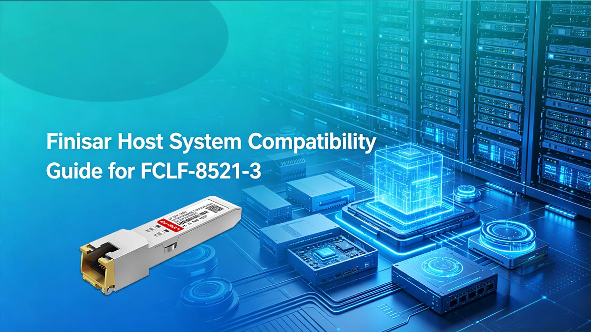
📝 Finisar Host System Compatibility Guide for FCLF-8521-3
Deploying the FCLF-8521-3 transceiver across enterprise switch fleets requires strict synchronization between the module's internal physical layer (PHY) microcode and the host network operating system (NOS). Properly aligning these low-level software and firmware parameters ensures immediate hardware recognition and port initialization, whether utilizing OEM original units or certified third-party compatible modules.
Native EEPROM Interoperability with Finisar Hardware
The internal EEPROM of the FCLF-8521-3 contains standardized multi-source agreement (MSA) memory maps that specify vital vendor data, serial numbers, and part codes. Fully compatible third-party modules duplicate these precise hexadecimal registers, allowing the host switch to natively read the transceiver signatures and initialize the interface without administrative override.
Firmware Validation Protocols for Seamless Switch Integration
Upon module insertion, the host switch executes automated cryptographic signature checks and validation protocols to verify hardware authenticity. The FCLF-8521-3 features optimized firmware designed to satisfy these system handshakes seamlessly, preventing port lockouts and ensuring immediate physical layer activation for both OEM and qualified third-party alternatives.
Configuring Finisar Operating Systems for 1000BASE-T Auto-Negotiation
To achieve line-rate throughput, the host NOS must be configured via the Command Line Interface (CLI) to allow the transceiver's hardware registers to handle full-duplex auto-negotiation. Both native and verified third-party FCLF-8521-3 modules utilize standard IEEE 802.3ab auto-negotiation channels, allowing seamless timing and master/slave clock alignment across multi-vendor switch environments.
Resolving Port Lockouts and Transceiver Recognition Errors in Finisar Switches
If the switch operating system flags a port as "unsupported" or triggers a software lockout, administrators can typically bypass the restriction by enabling specific CLI transceiver compliance commands. Deploying fully tested third-party compatible modules like the LINK-PP LP-SFP-TMRI SFP copper transceiver minimizes these layer 1 recognition errors from the outset, providing a highly reliable and mathematically predictable interface solution.
📝 Troubleshooting and Operational Procedures for FCLF-8521-3
Executing precise physical layer diagnostics and standardized handling protocols is essential for mitigating network downtime and preventing physical hardware degradation when deploying the FCLF-8521-3. Technicians must systematically isolate layer 1 signaling anomalies, enforce auto-negotiation standards, and implement proactive thermal management to maintain optimal operational efficiency inside high-density switch fabrics.
Proper Hot-Plugging and Safe Insertion/Removal Steps
While the FCLF-8521-3 is fully hot-pluggable, executing insertion and removal incorrectly can cause mechanical stress or port damage. Following a strict physical protocol ensures the internal gold pins mate perfectly with the host cage without creating electrical shorts.
- Align the transceiver housing horizontally with the SFP slot and slide it in until it clicks firmly into place.
- Always connect the RJ45 copper network patch cable only after the module is securely locked inside the port.
- Disconnect the RJ45 patch cable completely before attempting to pull the transceiver out of the switch.
- Flip the integrated metal bale-clasp downward to unlock the module from the chassis before pulling it straight out.
Diagnostic Logic Flow for Physical Link-Down Status
When an interface using the FCLF-8521-3 shows a stubborn physical link-down status, technicians should follow a structured diagnostic sequence. Isolating the failure points step-by-step prevents unnecessary hardware replacements and speeds up network recovery.
- Check the physical port LEDs and the switch command line interface to see if the port is administratively enabled.
- Inspect both ends of the RJ45 connector to confirm the cable is fully plugged in and clicked into place.
- Test the copper link with a verified patch cord to eliminate cable damage or termination faults.
- Move the transceiver to a known working switch port to verify if the original slot has an electrical issue.
Managing Auto-Negotiation vs. Forced Speed Mismatches
Duplex and speed mismatches occur when the FCLF-8521-3 and its downstream link partner are configured with conflicting port settings. Because this copper module relies heavily on hardware-based signaling, manual overrides can completely break the layer 1 connection.
- Configure both the host switch port and the far-end device interface to full auto-negotiation mode whenever possible.
- Avoid forcing a fixed speed of 1000Mbps on one end while leaving the other end set to auto-negotiate.
- Verify the duplex configuration matches exactly on both devices if you are forced to use manual settings.
- Check the switch error logs for duplex mismatch warnings if you notice slow data throughput or high collision rates.
Environmental Heat Dissipation Management in High-Density Line Cards
Copper SFP modules draw more power than optical modules, which causes them to generate significant heat when packed closely together. Managing this thermal output is essential to prevent internal chip overheating and premature component failure on the line card.
- Maintain a clean airflow path across the front panel of the switch by organizing external network cable bundles neatly.
- Space out copper transceivers across empty slots instead of packing them into adjacent ports when possible.
- Monitor system fan speeds and chassis temperature sensors regularly to ensure optimal cooling performance.
- Utilize blank slot panels on empty cages to maintain proper internal static pressure and uniform cooling airflow.
📝 Conclusion: Strategic Sourcing and Compatibility Solutions for the Finisar FCLF-8521-3

Successfully deploying the FCLF-8521-3 copper SFP across enterprise networks requires a careful balance of rigorous technical planning, proper physical layer maintenance, and smart hardware sourcing. By understanding its specific 1000BASE-T electrical properties, configuration protocols, and structural demands, network administrators can fully optimize their existing twisted-pair copper infrastructure while maintaining absolute line-rate stability.
When it comes to strategic procurement, utilizing verified third-party alternatives offers a highly dependable, budget-friendly option that completely avoids long factory lead times. If you are ready to expand your network capacity with fully tested, high-performance copper SFP transceivers, explore the selection available at the LINK-PP Official Store to find premium compatible solutions engineered for seamless host switch integration.


