
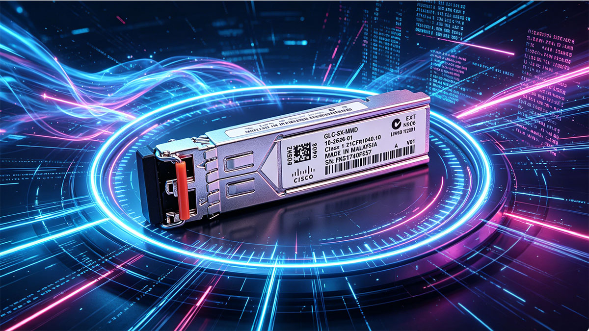
The Cisco 10-2626-01 is a 1000BASE-SX SFP optical transceiver designed for short-range Gigabit Ethernet transmission over multimode fiber. In most standard deployments, it operates reliably within defined IEEE specifications, but in real-world networks—especially those involving mixed vendors—compatibility and interoperability become critical factors that directly impact link stability and performance.
In practical scenarios, network engineers often encounter issues such as unsupported transceiver warnings, link failures between different brands of switches, or inconsistent diagnostic data. These challenges are not caused by the optical module alone, but by the interaction between hardware design, firmware policies, and industry standards such as IEEE 802.3z and SFP MSA. As a result, understanding how the Cisco 10-2626-01 behaves across different environments is essential for ensuring predictable network operation.
This guide focuses on the compatibility mechanisms and interoperability considerations of the Cisco 10-2626-01, providing a structured analysis of how it integrates with Cisco and third-party devices. It also explores the key factors that influence successful deployment and outlines practical methods to avoid common issues in multi-vendor Gigabit Ethernet networks.
♦️ Overview of Cisco 10-2626-01 Transceiver
The Cisco 10-2626-01 is a 1000BASE-SX SFP optical transceiver designed for Gigabit Ethernet transmission over multimode fiber. In practical use, it serves as a short-reach optical interface that enables high-speed connectivity within enterprise networks and data center environments. Its design is based on widely adopted industry standards, which makes it suitable for a broad range of compatible networking platforms, provided that optical and firmware requirements are properly aligned.
From a deployment perspective, this module is typically used in access and aggregation layers where distances are relatively short and fiber infrastructure is already based on multimode cabling. Because it operates at 850nm wavelength and supports standardized Gigabit Ethernet signaling, it is commonly integrated into switch-to-switch or switch-to-server links within structured cabling systems.
Key Specifications and Technical Characteristics
To understand how the Cisco 10-2626-01 performs in real environments, it is important to review its core technical attributes. These parameters define its physical limitations, compatibility boundaries, and deployment suitability.
The following table summarizes the main specifications of the module:
| Parameter |
Specification |
Relevance |
| Form Factor |
SFP (Small Form-factor Pluggable) |
Ensures modular hot-swappable design |
| Data Rate |
1Gbps (Gigabit Ethernet) |
Standard enterprise access speed |
| Wavelength |
850nm |
Optimized for multimode fiber transmission |
| Max Distance |
Up to 550m (OM2), 220m (OM1) |
Depends on fiber quality |
| Connector Type |
Duplex LC |
Industry-standard fiber interface |
These specifications indicate that the module is optimized for short-range, high-density networking environments. In particular, the 850nm wavelength choice aligns with multimode fiber characteristics, enabling cost-effective intra-building connectivity.
Beyond raw specifications, one important operational consideration is optical budget planning. While the module supports up to 550 meters on OM2 fiber, actual achievable distance depends on factors such as fiber aging, connector quality, and splice losses. Therefore, real-world deployment often requires conservative margin planning rather than relying solely on theoretical maximums.
Typical Deployment Scenarios
In real network architectures, the Cisco 10-2626-01 is not used in isolation but as part of structured Gigabit Ethernet topologies. Its deployment is generally driven by distance requirements, port availability, and existing fiber infrastructure.
Common usage scenarios include:
- Switch-to-switch uplinks within enterprise campus networks
- Aggregation layer connections in data center racks
- Server-to-switch connectivity in high-density environments
- Legacy network upgrades transitioning from copper-based Fast Ethernet to fiber-based Gigabit Ethernet
These scenarios typically share a common requirement: stable short-distance optical connectivity within controlled environments. Because of this, the module is rarely used for long-haul or single-mode applications, where different optical characteristics would be required.
In addition, its compatibility with existing multimode fiber infrastructure makes it particularly attractive in environments where fiber rewiring is not feasible. This allows organizations to upgrade bandwidth without significant physical layer changes, provided that compatibility across vendor equipment is properly validated.
♦️ Understanding Compatibility in Optical Transceivers
Compatibility in optical transceivers refers to whether a module can be correctly recognized, powered, and used by a networking device while maintaining stable optical communication. In the context of Cisco 10-2626-01, compatibility is not only about physical fit or matching speed, but also about firmware recognition, vendor coding rules, and adherence to IEEE optical standards. Even when two devices support 1000BASE-SX, interoperability is not always guaranteed without proper validation of these layers.
In real network environments, compatibility issues typically appear during initial deployment or when upgrading firmware on switches. A transceiver that worked previously may suddenly trigger warnings or fail to initialize due to changes in device-side validation policies. This is why understanding both standards-based compatibility and vendor-specific restrictions is essential for stable operation.
What Compatibility Means in Networking Context
In optical networking, compatibility operates on multiple technical layers rather than a single attribute. It involves hardware alignment, protocol compliance, and device recognition behavior working together.
To clarify how compatibility is evaluated, the key dimensions are summarized below:
| Dimension |
Description |
Impact on Operation |
| Physical Compatibility |
Matching form factor and connector type (SFP, LC duplex) |
Determines if module can be installed |
| Optical Compatibility |
Alignment of wavelength and fiber type |
Affects signal transmission quality |
| Protocol Compatibility |
IEEE 802.3z compliance for Gigabit Ethernet |
Ensures correct data encoding |
| Vendor Compatibility |
Device recognition via EEPROM coding |
Determines if module is accepted by switch |
These layers work together to determine whether a Cisco 10-2626-01 module will function seamlessly in a given environment. In practice, even if optical and protocol parameters match, vendor compatibility may still restrict usage depending on the switch’s firmware policy.
From an engineering perspective, standards compliance ensures that the module can technically transmit data correctly, but vendor compatibility determines whether the device will allow it to operate without warnings or administrative overrides.
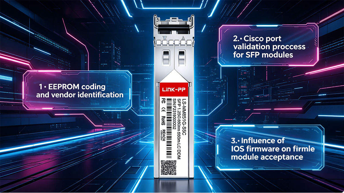
Cisco Compatibility Mechanism Explained
Cisco networking devices implement a compatibility verification process that goes beyond basic optical signaling. When a Cisco 10-2626-01 module is inserted into a switch, the system reads the EEPROM data stored inside the transceiver to identify its vendor, model, and supported specifications.
The behavior of this mechanism can be summarized as follows:
- The switch reads the transceiver’s identification data during initialization
- Firmware compares this data against an internal compatibility database
- If the module matches approved entries, it is fully enabled
- If not, the system may display warnings such as “unsupported transceiver”
- In some cases, functionality may still work but with restricted support status
This validation process is one of the most common sources of confusion in mixed-vendor environments. Technically, a non-Cisco-coded module may still operate correctly at the optical layer, but the device may not officially recognize it.
Another important factor is firmware version dependency. Different Cisco IOS or NX-OS versions may expand or restrict supported transceiver lists. As a result, a module’s compatibility status can change after a software upgrade, even if the hardware remains unchanged.
From a practical standpoint, this means that compatibility is not static. It is a dynamic relationship between the transceiver, the switch hardware, and the running firmware version. Understanding this interaction is essential for preventing unexpected link behavior in production networks.
♦️ Interoperability Between Cisco 10-2626-01 and Third-Party Devices
Interoperability between the Cisco 10-2626-01 and third-party networking equipment refers to the ability of this 1000BASE-SX SFP module to establish and maintain stable Gigabit Ethernet links when paired with non-Cisco switches or optical systems. In practical deployments, this is one of the most important considerations in mixed-vendor environments, where optical standards compliance often matters more than vendor branding.
In most cases, the Cisco 10-2626-01 can technically interoperate with third-party devices because it follows the IEEE 802.3z Gigabit Ethernet and SFP Multi-Source Agreement (MSA) specifications. However, successful operation depends on correct alignment of optical parameters, firmware behavior, and link negotiation expectations on both ends of the connection.
Cross-Vendor Interoperability Basics
At the physical layer, Gigabit Ethernet over multimode fiber is largely standardized, meaning that transceivers from different vendors can communicate if their optical characteristics match. For the Cisco 10-2626-01, this primarily involves 850nm wavelength operation and multimode fiber support.
The core conditions required for interoperability can be summarized as follows:
- Both devices must support 1000BASE-SX (1Gbps over multimode fiber)
- Fiber type must match (typically OM1, OM2, or higher-grade multimode fiber)
- Wavelength must be aligned (850nm on both ends)
- Optical power levels must fall within receiver sensitivity ranges
- Duplex LC connectivity must be correctly installed and clean
These conditions ensure that the optical signal can be transmitted and received correctly, regardless of vendor differences. In most cases, if these parameters are satisfied, the link will come up successfully even if one side is Cisco and the other is a third-party switch.
Common Interoperability Scenarios
In real-world networks, Cisco 10-2626-01 modules are frequently deployed in mixed environments. The behavior of these links varies depending on device compatibility policies and network design choices.
Typical interoperability scenarios include:
- Cisco switch connected to a non-Cisco enterprise switch using 1000BASE-SX
- Legacy Cisco infrastructure integrated with modern third-party aggregation switches
- Data center environments where server NICs use third-party SFP modules
- Campus networks combining multiple vendors for cost and scalability reasons
In these environments, the physical link often establishes successfully, but operational visibility may differ. For example, Cisco devices may show limited diagnostic information if the transceiver is not officially recognized, while third-party devices may fully accept the module without restrictions.
Real-World Interoperability Challenges
Although IEEE standards provide a strong foundation for cross-vendor connectivity, several practical challenges can still affect stability and visibility in mixed environments.
A summary of common issues is shown below:
| Issue Type |
Description |
Impact on Network |
| Vendor Coding Mismatch |
Cisco EEPROM not recognized by third-party firmware or vice versa |
May trigger warnings or unsupported status |
| DOM Data Inconsistency |
Differences in Digital Optical Monitoring implementation |
Reduced diagnostic visibility |
| Firmware Behavior Differences |
Varying transceiver acceptance policies across vendors |
Link may be blocked or restricted |
| Power Budget Misalignment |
Optical levels slightly outside expected thresholds |
Intermittent link instability |
These issues do not necessarily prevent physical link establishment, but they can affect operational monitoring and long-term stability. In particular, firmware-based restrictions are one of the most common reasons why a technically compatible link may still fail to initialize on certain devices.
Another important factor is that interoperability is not purely static. Firmware upgrades on either Cisco or third-party devices can change how transceivers are interpreted, potentially introducing new restrictions or improving compatibility depending on vendor policy updates.
From an engineering perspective, ensuring interoperability is therefore not only about matching optical specifications, but also about validating behavior across device firmware versions in the intended deployment environment.
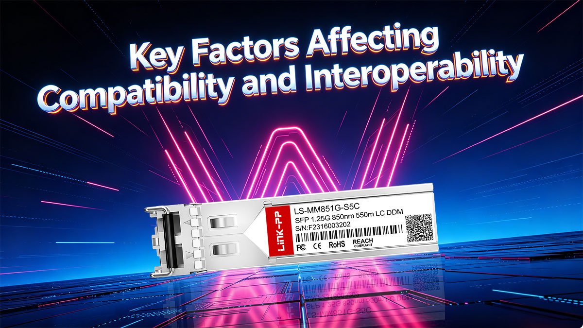
♦️ Key Factors Affecting Compatibility and Interoperability
Compatibility and interoperability of the Cisco 10-2626-01 in real networks are determined by a combination of physical layer constraints, software behavior, and industry standards alignment. Even though the module follows the 1000BASE-SX specification, stable operation across different environments depends on multiple interdependent factors. Understanding these factors helps prevent link instability, recognition issues, and inconsistent diagnostic behavior in mixed-vendor deployments.
In practice, most interoperability problems are not caused by the optical transceiver itself, but by mismatches between optical budgets, firmware policies, or fiber infrastructure quality. These elements collectively define whether a link will operate reliably under real-world conditions.
Hardware-Level Considerations
At the physical layer, compatibility is primarily influenced by optical performance characteristics and fiber infrastructure quality. The Cisco 10-2626-01 is designed for multimode fiber transmission at 850nm, but actual performance depends heavily on deployment conditions.
Key hardware factors include:
- Optical power budget alignment between transmitting and receiving ends
- Fiber type consistency (OM1, OM2, OM3, or higher-grade multimode fiber)
- Connector condition, including cleanliness and physical wear
- Insertion loss caused by patch panels, splices, and cable length
- Port hardware capability on connected switches or NICs
These factors directly affect whether the optical signal remains within the receiver sensitivity range. For example, even if a link is within the theoretical 550m range on OM2 fiber, excessive connector loss or degraded fiber quality can significantly reduce usable distance.
The following table summarizes how key physical parameters influence interoperability:
| Factor |
Description |
Impact on Compatibility |
| Optical Power Budget |
Difference between transmit power and receive sensitivity |
Determines maximum stable link distance |
| Fiber Grade |
Quality of multimode fiber (OM1–OM3+) |
Affects attenuation and bandwidth support |
| Connector Loss |
Signal loss at LC interfaces and patch points |
Can cause marginal or unstable links |
| Physical Cleanliness |
Contamination on fiber ends |
Leads to signal degradation or link failure |
When these hardware factors are properly controlled, the Cisco 10-2626-01 can operate reliably even in heterogeneous network environments.
Software and Firmware Dependencies
Beyond physical layer conditions, software and firmware behavior plays a critical role in determining whether a transceiver is accepted and functions correctly. Cisco devices, in particular, apply validation rules that can affect module recognition.
Important software-related factors include:
- IOS or NX-OS version compatibility with specific transceivers
- Vendor-coded EEPROM recognition rules
- “Unsupported transceiver” warnings and policy enforcement
- DOM (Digital Optical Monitoring) feature support differences
- Administrative overrides allowing or restricting module operation
Firmware behavior can significantly change interoperability outcomes. A module that works without issues on one software version may generate warnings or be blocked on another due to updated compatibility databases.
In mixed environments, third-party switches may adopt more permissive policies, accepting standard-compliant SFP modules without strict vendor validation. However, this can create inconsistencies in monitoring visibility, especially when comparing optical diagnostics across devices.
Therefore, firmware alignment across all network devices is essential to ensure consistent behavior and predictable troubleshooting results.
Standards and Protocol Alignment
The foundation of interoperability for the Cisco 10-2626-01 lies in adherence to IEEE 802.3z Gigabit Ethernet standards and the SFP Multi-Source Agreement (MSA). These standards define how optical modules should behave at the physical and data link layers, ensuring baseline compatibility across vendors.
Key standards-related considerations include:
- IEEE 802.3z defines Gigabit Ethernet over fiber (1000BASE-SX)
- SFP MSA defines physical form factor and electrical interface
- Optical wavelength standardization at 850nm for multimode operation
- Lack of mandatory auto-negotiation in fiber-based Gigabit links
Because Gigabit fiber links do not rely heavily on auto-negotiation like copper Ethernet, interoperability depends more on fixed parameters such as speed, wavelength, and fiber type. This makes standards compliance essential but not always sufficient when vendor-specific validation is applied.
In well-aligned environments where both hardware and firmware respect these standards consistently, the Cisco 10-2626-01 can interoperate reliably across a wide range of third-party devices. However, deviations in implementation—especially at the firmware validation layer—remain the primary source of cross-vendor compatibility challenges.
♦️ Best Practices for Ensuring Seamless Compatibility
Ensuring seamless compatibility for the Cisco 10-2626-01 in real-world deployments requires a combination of pre-deployment validation, physical layer discipline, and consistent configuration management. Although the module is based on standardized 1000BASE-SX specifications, practical interoperability issues often arise from environmental factors, firmware policies, or mismatched deployment assumptions rather than the transceiver itself.
In most stable networks, compatibility is achieved not by a single configuration change, but by following a structured validation process before and after deployment. This reduces the risk of link instability, unsupported transceiver alerts, and inconsistent optical performance across devices.
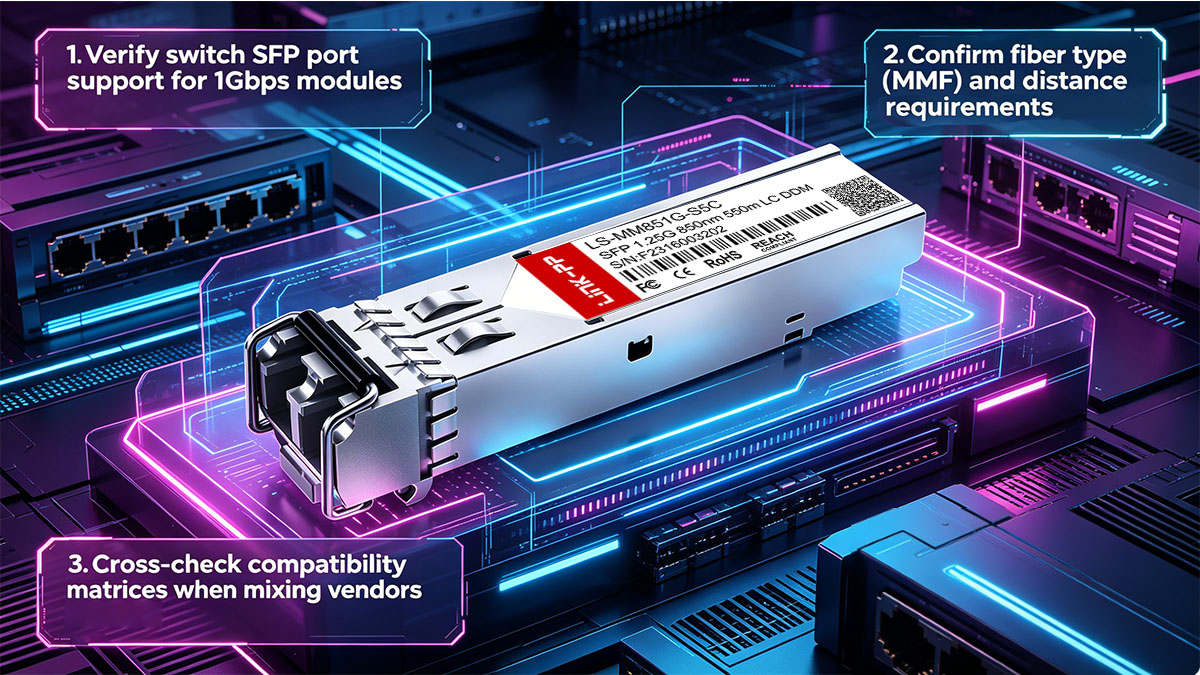
Pre-Deployment Validation Steps
Before installing the Cisco 10-2626-01 into a production environment, it is essential to confirm that both the hardware and network design are aligned with its operational requirements. This step significantly reduces interoperability risks in mixed-vendor environments.
Key validation steps include:
- Confirm switch SFP port supports 1000BASE-SX (1Gbps over multimode fiber)
- Verify fiber infrastructure type (OM1, OM2, or OM3 multimode fiber)
- Ensure link distance does not exceed optical budget limits
- Check compatibility matrix between Cisco and third-party devices if applicable
- Validate firmware versions on all connected networking equipment
These checks help ensure that the module operates within its intended design parameters. In particular, fiber type and distance validation are critical, as mismatches here often lead to marginal or unstable links even when the transceiver is technically compatible.
Testing and Verification Methods
After installation, systematic testing is necessary to confirm that the optical link is stable and performing within acceptable parameters. This stage focuses on both physical layer verification and operational behavior under real traffic conditions.
Common testing methods include:
- Link status verification using interface LEDs or CLI commands
- Optical power measurement using a fiber power meter
- Checking DOM values (if supported) for transmit and receive power levels
- Monitoring error counters such as CRC errors or frame drops
- Performing traffic load tests to evaluate stability under utilization
These methods help identify early signs of incompatibility, such as marginal optical levels or firmware-related restrictions. In many cases, issues that appear as intermittent connectivity problems can be traced back to borderline optical power budgets or unclean fiber connections.
A key best practice is to establish baseline measurements immediately after deployment. This provides a reference point for future troubleshooting and helps detect gradual degradation over time.
Documentation and Labeling Strategies
Long-term compatibility stability depends not only on technical configuration but also on operational discipline. Proper documentation and labeling reduce the likelihood of configuration drift and simplify troubleshooting in complex network environments.
Recommended practices include:
- Maintain an inventory of all Cisco 10-2626-01 modules in use
- Record associated switch ports and connected devices
- Label fiber cables with type (OM1/OM2/OM3) and link purpose
- Track firmware versions across all network devices
- Document optical power readings during initial deployment
These practices are especially important in multi-vendor environments where different devices may interpret transceiver behavior differently. Clear documentation ensures that future changes—such as firmware upgrades or hardware replacements—do not unintentionally introduce compatibility issues.
In large-scale networks, consistent labeling and record-keeping also reduce mean time to repair (MTTR), as engineers can quickly identify whether a problem is related to physical layer conditions, configuration changes, or device compatibility behavior.
♦️ Troubleshooting Compatibility and Interoperability Issues
When the Cisco 10-2626-01 is deployed in mixed or large-scale Gigabit Ethernet environments, compatibility and interoperability issues typically appear as link instability, non-recognition of the module, or degraded optical performance. In most cases, these problems are not caused by a single fault but by a combination of physical layer conditions, firmware validation behavior, and fiber infrastructure quality.
Effective troubleshooting requires a structured approach that separates physical, optical, and software-related causes. This helps quickly identify whether the issue is related to the transceiver itself, the connected device, or the fiber link between them.
Identifying Common Symptoms
Before performing detailed diagnostics, it is important to recognize the typical symptoms associated with compatibility or interoperability problems. These symptoms often provide early indicators of where the issue originates.
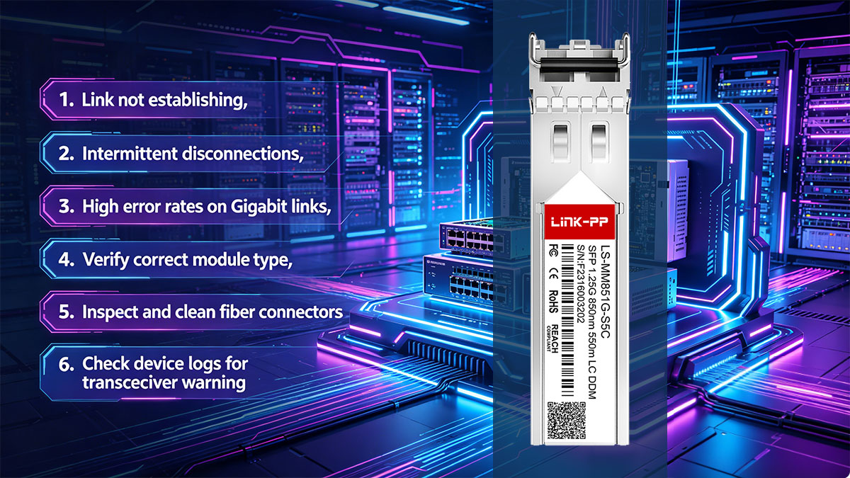
Common symptoms include:
- Link status remains down even after module insertion
- Intermittent link flapping or unstable connectivity
- High error rates such as CRC or frame alignment errors
- “Unsupported transceiver” or similar system warnings
- Missing or incomplete DOM (Digital Optical Monitoring) data
- Reduced throughput compared to expected Gigabit performance
These symptoms may appear individually or in combination. For example, a link may establish successfully but still experience high error rates due to marginal optical power levels or fiber degradation.
Step-by-Step Troubleshooting Approach
A structured troubleshooting process helps isolate the root cause efficiently. Instead of immediately replacing components, each layer should be validated in sequence to determine whether the issue is physical, optical, or software-related.
A recommended troubleshooting flow includes:
- Verify physical installation of the Cisco 10-2626-01 module
- Confirm correct fiber type and polarity (Tx/Rx alignment)
- Inspect and clean LC connectors to eliminate contamination issues
- Check switch interface status and transceiver recognition
- Validate optical power levels against expected ranges
- Compare firmware versions on connected devices
- Test link stability under controlled traffic conditions
This approach ensures that simple issues such as reversed fiber pairs or dirty connectors are eliminated before investigating more complex firmware or interoperability problems. In many real-world cases, physical layer corrections alone resolve the issue without requiring configuration changes.
Tools and Commands for Diagnostics
Accurate diagnostics require both hardware tools and software-based monitoring utilities. Cisco devices provide built-in commands to evaluate transceiver status and optical performance, while external tools can validate physical fiber conditions.
Common diagnostic tools and methods include:
- Cisco CLI commands such as interface status and transceiver inventory checks
- Optical diagnostics via DOM readings (Tx/Rx power, temperature, voltage)
- Show interface counters for CRC errors, input/output drops, and link resets
- Fiber inspection tools such as visual fault locators (VFL)
- Optical power meters for precise signal strength measurement
These tools help distinguish between different failure modes. For example, strong optical power but high error rates often indicate protocol or compatibility issues, while weak optical power typically points to fiber loss or physical degradation.
A key best practice is to compare DOM readings on both ends of the link. Significant imbalance between transmit and receive power can indicate fiber attenuation issues, dirty connectors, or mismatched optical budgets. This comparison is especially useful in mixed-vendor environments where monitoring visibility may differ between devices.
By combining systematic step-by-step checks with reliable diagnostic tools, most Cisco 10-2626-01 compatibility and interoperability issues can be identified and resolved efficiently without unnecessary hardware replacement.
♦️ Cisco 10-2626-01 vs Compatible Alternatives
When deploying the Cisco 10-2626-01 in real network environments, a common consideration is whether to use the original Cisco-branded module or a compatible third-party alternative. Both options are generally based on the same 1000BASE-SX (IEEE 802.3z) standard, but they differ in areas such as device recognition behavior, interoperability flexibility, and operational management within Cisco-controlled ecosystems.
In practice, the choice is not only about optical performance, but also about network policy, scale of deployment, and the level of vendor control enforced by switching infrastructure.
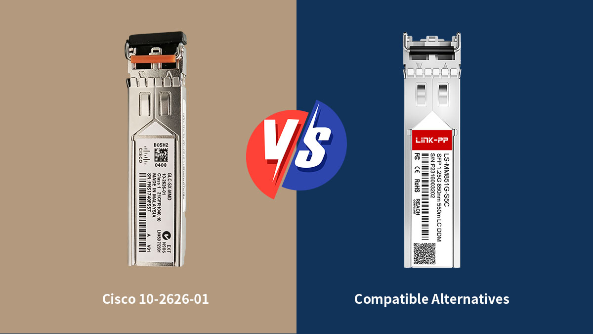
Differences Between OEM and Compatible Modules
Although both Cisco OEM modules and compatible alternatives are designed to meet the same optical transmission standards, their behavior at the system level can differ significantly due to EEPROM coding, firmware validation, and support policies.
The following table summarizes the key differences:
| Aspect |
Cisco 10-2626-01 (OEM) |
Compatible Alternatives |
| Standards Compliance |
Fully IEEE 802.3z compliant |
Also compliant if properly manufactured |
| Device Recognition |
Fully recognized by Cisco systems |
May trigger warnings on Cisco devices |
| Firmware Behavior |
Fully supported in Cisco IOS/NX-OS |
Dependent on vendor coding |
| Interoperability |
High in Cisco-native environments |
Often broader cross-vendor flexibility |
| Monitoring (DOM) |
Full support and consistency |
May vary by vendor implementation |
From an operational perspective, OEM modules typically provide the most predictable behavior in Cisco-centric networks. They are fully recognized by the device firmware, which ensures complete visibility of diagnostic data and eliminates compatibility warnings.
Compatible modules, however, are often designed to maximize flexibility across multi-vendor environments. While they adhere to optical standards, their system-level behavior can vary depending on how strictly different devices enforce transceiver validation rules.
When to Consider Compatible Options
In real-world deployments, compatible alternatives are often evaluated based on scalability, heterogeneity of the network environment, and operational constraints rather than pure technical capability.
Common scenarios where compatible modules are considered include:
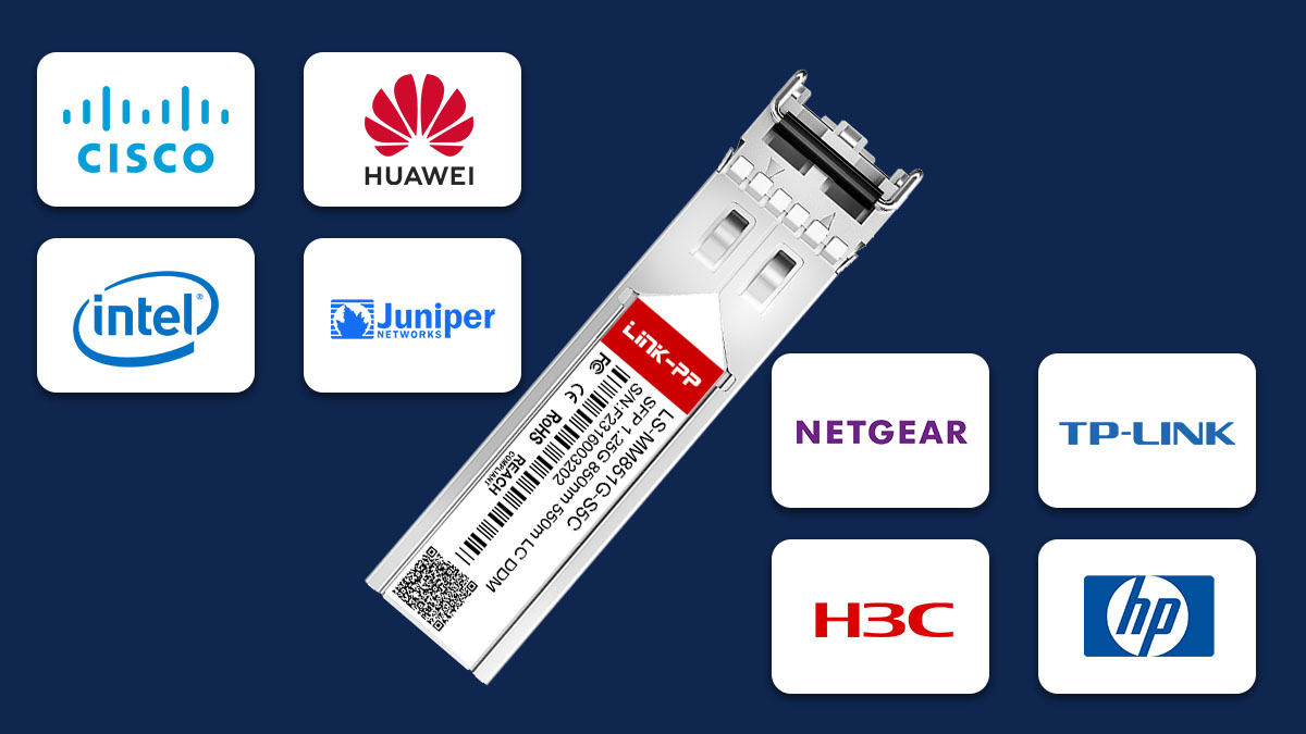
- Multi-vendor networks combining Cisco, Juniper, HP, or other switches
- Large-scale deployments where cost efficiency is a key factor
- Legacy infrastructure upgrades requiring mixed hardware integration
- Non-critical network segments where full vendor validation is not mandatory
- Lab, testing, or staging environments requiring flexible hardware usage
In these situations, compatible modules can provide sufficient performance as long as they adhere strictly to 1000BASE-SX optical standards and maintain stable power characteristics.
However, in Cisco-restricted environments where firmware enforces strict transceiver validation, compatible modules may generate warning messages or be limited in monitoring capability. This does not always prevent physical link operation, but it can reduce operational visibility and complicate long-term maintenance.
Ultimately, the decision between Cisco 10-2626-01 and compatible alternatives depends on the balance between operational predictability and deployment flexibility. Networks prioritizing stability and full vendor support typically favor OEM modules, while environments emphasizing interoperability and cost efficiency may adopt compatible solutions under proper validation controls.
♦️ FAQs about Cisco 10-2626-01
What is Cisco 10-2626-01 used for?
It is a 1000BASE-SX SFP optical transceiver used for Gigabit Ethernet connections over multimode fiber in short-range network environments such as enterprise and data center links.
What fiber type is required for Cisco 10-2626-01?
It requires multimode fiber (MMF), typically OM1, OM2, or higher grades like OM3, operating at 850nm wavelength for short-distance transmission.
What is the maximum transmission distance of Cisco 10-2626-01?
It supports up to 550 meters on OM2 multimode fiber and approximately 220 meters on OM1 fiber under ideal conditions.
Why does Cisco show “unsupported transceiver” warning?
This usually occurs due to Cisco’s EEPROM coding validation, where non-approved or third-party coded modules are not fully recognized by the device firmware.
Can Cisco 10-2626-01 work with non-Cisco switches?
Yes, it can interoperate with third-party switches if both sides support 1000BASE-SX and use compatible multimode fiber and optical parameters.
What causes link instability with Cisco 10-2626-01?
Common causes include dirty fiber connectors, mismatched fiber types, optical power imbalance, or firmware-related compatibility restrictions.
Why does a compatible module sometimes work but show warnings?
Because it meets optical standards but may not match Cisco’s internal vendor coding database, resulting in functional operation with limited system recognition.
♦️ Conclusion
The Cisco 10-2626-01, as a 1000BASE-SX SFP optical transceiver, plays a stable and widely used role in Gigabit Ethernet networks, but its real-world performance is strongly influenced by compatibility and interoperability factors across devices, firmware, and fiber infrastructure.
From a technical perspective, successful deployment depends not only on meeting IEEE 802.3z standards, but also on how Cisco device-side validation, third-party switch behavior, and optical conditions interact in mixed environments. Understanding these relationships helps ensure consistent link stability and avoids common issues such as unsupported transceiver warnings, link failures, or degraded optical performance.
To summarize the key insights covered in this guide:
- Cisco 10-2626-01 is a 1000BASE-SX (1Gbps) SFP module designed for multimode fiber short-reach connections
- Compatibility depends on a combination of IEEE standards compliance and vendor-specific firmware validation rules
- Interoperability in mixed-vendor environments is achievable when optical parameters (850nm, MMF, power budget) are properly aligned
- Most real-world issues originate from physical layer conditions, firmware restrictions, or fiber quality rather than the module itself
- Proper testing, documentation, and diagnostics significantly improve long-term network stability
These points highlight that stable operation is not defined by the transceiver alone, but by the entire optical ecosystem in which it operates.
In modern network infrastructures, especially those with mixed vendors and evolving upgrade paths, selecting the right optical strategy is as important as selecting the module itself. Ensuring compatibility at both hardware and software levels helps maintain predictable performance and reduces operational risk over time.
For organizations seeking reliable optical transceiver solutions with strong compatibility across different network environments, LINK-PP Official Store provides a wide range of industrial-grade optical modules designed to support stable Gigabit Ethernet deployments and cross-platform interoperability requirements.


