Can a 1x5 QSFP-DD cage realistically maintain clean 800G transmission when squeezed onto an overcrowded 1U switch faceplate? As hyperscale operators accelerate high-density data center deployment, cramming five high-speed ports into tight rack units has quickly become an operational necessity. Yet, stacking this much raw throughput into a 1.75-inch chassis height pushes physical hardware boundaries to the absolute edge.
What happens to sensitive 112G PAM4 signals when channel loss, dense crosstalk, and intense thermal dissipation collide on the host board? Running at high 28GHz Nyquist frequencies leaves hardware designers with razor-thin insertion loss margins across standard PCB traces. Can modern interconnect engineering actually overcome these severe physical constraints to deliver reliable signal integrity in real-world deployment?
❇️ What Makes the 1x5 QSFP-DD Cage Vital for 1U High-Density Switches?
Meeting soaring bandwidth demands in modern computing clusters requires packing immense switching capacity into standard rack footprints. Deploying a compact 1x5 QSFP-DD cage delivers the precise mechanical density and channel layout needed to unlock scalable 800G connectivity across modern enterprise switch designs.
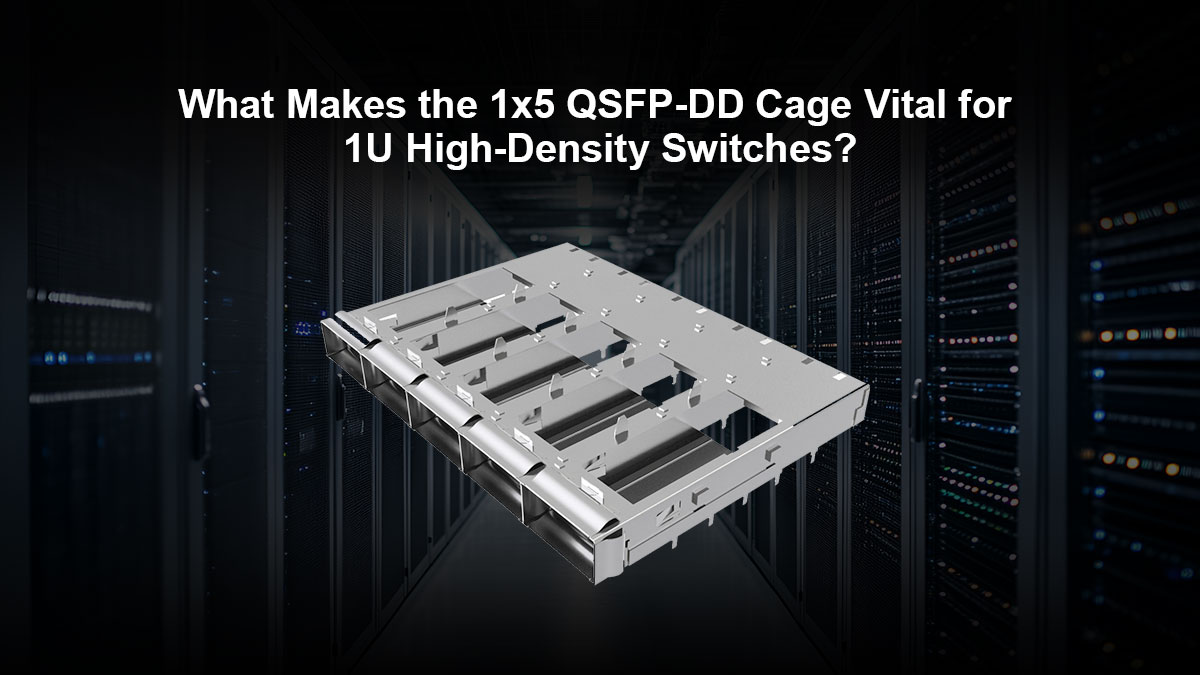
Understanding the 800G Front-Panel Density Bottleneck
Standard 1U front panels offer barely 19 inches of horizontal width, forcing hardware architects to maximize every millimeter of usable faceplate space. Integrating a 1x5 QSFP-DD cage allows platform designers to group five high-speed interfaces without blocking intake airflow vents. To achieve this balance, hardware teams must address several interrelated mechanical factors:
- Space constraints: A 1U chassis restricts vertical clearance to 44.45 mm, leaving zero room for stacked multi-deck cages.
- Throughput targets: Five grouped ports deliver a massive 4.0 Tbps aggregate throughput across a compact front-panel zone.
- Layout harmony: Preserves vital faceplate real estate for management ports, optical status LEDs, and system thermal exhaust.
How 8x112G PAM4 Signaling Changes the Hardware Game
Upgrading from 400G to 800G transitions the physical layer to eight differential pairs operating at 112Gbps PAM4 per port. Unlike binary NRZ modulation, PAM4 packs two bits per symbol by splitting the signal voltage into four distinct amplitude levels.
Because eye heights shrink by approximately 9.5dB compared to legacy signaling, 112G channels exhibit zero tolerance for impedance mismatches. Consequently, the internal contacts within a 1x5 QSFP-DD cage must maintain exceptionally uniform return loss across all forty high-speed differential pairs.
Why Hyperscale Data Centers Prefer 1U Modular Footprints
Modern hyperscale cloud architectures favor flat, single-rack-unit leaf and spine switches to achieve maximum operational flexibility. Deploying 1U boxes populated with 1x5 QSFP-DD cage modules eliminates stranded bandwidth while keeping rack cabling organized and serviceable. This modular approach delivers distinct operational advantages across large-scale deployments:
- Pay-as-you-grow scaling: Modular 1U building blocks allow operators to expand spine fabrics incrementally without purchasing oversized chassis.
- Blast radius containment: Single-unit failures affect only a small cluster segment rather than an entire multi-blade system.
- Airflow alignment: Shallow 1U enclosures optimize straight-through front-to-back cooling across dense server aisles.
Balancing Maximum Port Count with Board Reliability
Pushing faceplate density to the absolute edge creates severe routing congestion beneath the host mainboard. Spacing ports across a 1x5 QSFP-DD cage provides the necessary physical footprint to balance high connector density against board fabrication yields.
Grouping five connectors into a unified metal cage structure ensures shared mechanical grounding and structural rigidity during rough field insertions. This monolithic design prevents localized board warping and protects fragile solder ball arrays from long-term mechanical shear stress.
❇️ Is the 1x5 QSFP-DD Cage Capable of Meeting IEEE 802.3ck C2M Budgets?
Achieving the high port density demanded by 1U switching platforms depends entirely on keeping high-speed signals within strict electrical compliance boundaries. While deploying a 1x5 QSFP-DD cage solves the physical front-panel equation, proving whether it can operate within the razor-thin insertion loss margins of IEEE 802.3ck requires rigorous channel budgeting.

Mapping the 16 dB Channel Insertion Loss Limit at 28 GHz
The IEEE 802.3ck Chip-to-Module (C2M) specification defines a strict total channel insertion loss limit of 16.0 dB at the 28 GHz Nyquist frequency. This finite allocation covers the entire electrical path from the switch ASIC die pads to the optical transceiver input.
In a high-density 1U system, host PCB routing consumes the majority of this headroom before the signal even reaches the 1x5 QSFP-DD cage. Consequently, the cage assembly and its internal connector contacts must strictly limit loss to under 1.5 dB to ensure the remaining link closes successfully.
Where Most Signal Attenuation Occurs Along the Host Board
High-frequency signal decay is not uniform across the host board, but rather concentrates heavily at geometric transitions. The primary culprits include package ball grid array (BGA) breakouts, AC coupling capacitor pads, and connector through-hole via transitions.
At 28 GHz, dielectric dissipation and skin effect resistance rapidly strip energy from the 112G differential pairs. If routing behind the 1x5 QSFP-DD cage is unoptimized, unmitigated via stubs and pad discontinuities will burn through the IEEE loss budget long before reaching the front panel.
Overcoming Trace Length Discrepancies Across Outer Ports
In a side-by-side 1x5 QSFP-DD cage configuration, horizontal port dispersion inevitably creates uneven trace lengths from a centered switch ASIC. Signals traveling to the peripheral outer ports must traverse significantly longer PCB paths than those routed to the inner channels.
This physical distance disparity threatens to push outer lanes past the 16 dB threshold while inner lanes remain fully compliant. Hardware architects compensate by implementing careful layer transitions and assigning outer ports to the thickest, lowest-loss signal layers to equalize attenuation across all five ports.
Realistic Eye Diagram Margins for Production Hardware
Passing numerical insertion loss simulations does not automatically guarantee clean 800G operation on an active manufacturing line. Real-world PAM4 eye openings must provide adequate vertical eye height and horizontal eye width to accommodate manufacturing variances, component tolerances, and thermal drift.
When pairing an optimized 1x5 QSFP-DD cage with modern DSP equalizers, production boards can maintain healthy inner-eye margins well above the IEEE 802.3ck minimum mask. This electrical headroom ensures stable, low-bit-error-rate performance across massive, continuous data center workloads.
❇️ How High-Frequency Crosstalk Threatens Your 1x5 QSFP-DD Cage Layout
While conquering insertion loss keeps signals strong across the host board, preventing unwanted noise coupling between closely spaced differential pairs presents an equally formidable hurdle. In high-density 1U front panels where forty 112G PAM4 lanes operate simultaneously, a 1x5 QSFP-DD cage must suppress high-frequency electromagnetic interference before multi-port crosstalk destroys system margins.
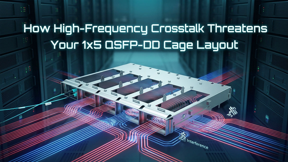
Understanding NEXT and FEXT Spikes Across Tightly Packed Ports
In a multi-port ganged configuration, high-speed signals inevitably radiate electromagnetic fields into adjacent channels. Near-End Crosstalk (NEXT) and Far-End Crosstalk (FEXT) represent two distinct noise coupling paths that scale rapidly as port spacing narrows. Evaluating how these mechanisms interfere with high-frequency transmission reveals why dense front-panel clustering requires exceptional channel isolation:
| Crosstalk Mechanism | Coupling Mechanism | Impact on 112G PAM4 Performance | Mitigation Target in 1U Cages |
| Near-End Crosstalk (NEXT) | High-power local transmitter leaks noise directly into neighboring weak receiver pins. | Causes severe signal-to-noise ratio (SNR) degradation at the local host DSP. | Requires dedicated ground shielding blades between adjacent ports in the 1x5 QSFP-DD cage. |
| Far-End Crosstalk (FEXT) | Transmit noise travels alongside victim lanes, accumulating energy along the channel. | Distorts waveform edges and induces high-frequency jitter at the remote optical module. | Demands wide pair-to-pair isolation spacing and optimized anti-pad clearance cutouts. |
Because 800G transmission operates with four-level PAM4 signaling, even minor crosstalk spikes can collapse the delicate signal eyes. Ensuring comprehensive isolation across the 1x5 QSFP-DD cage footprint remains vital to prevent neighboring aggressor channels from exceeding IEEE 802.3ck limits.
How Dense Connector Pin Fields Leak Energy into Adjacent Lanes
The connector pin field represents the densest electrical bottleneck on the entire host board. Each port within a 1x5 QSFP-DD cage houses 76 pins positioned at an ultratight 0.8mm pitch, creating significant capacitive and inductive fringe fields. To maintain clear signal paths, hardware engineers must isolate specific coupling zones:
- Solder tail transitions: High-speed differential pairs transitioning from the connector pins to internal PCB layers lose their coaxial shielding, exposing adjacent signals to unattenuated fringe fields.
- Layer-to-layer vertical coupling: Signal vias passing through dense power and ground planes create parasitic capacitance if clearance anti-pads overlap between neighboring lanes.
- Shared reference plane discontinuities: Inadequate grounding around connector press-fit pins forces return currents to take indirect paths, generating common-mode noise across adjoining high-speed lanes.
The Dangerous Coupling Between TX and RX Channels at 28 GHz
Operating at a 28 GHz Nyquist frequency dramatically intensifies electromagnetic coupling between transmit (TX) and receive (RX) lanes. A transmitting lane delivers maximum signal amplitude, while an incoming receive lane carries heavily attenuated, fragile signals that have already suffered board-level insertion loss.
If high-energy TX lanes couple into sensitive RX lanes within the 1x5 QSFP-DD cage, the resulting NEXT noise easily swamps the incoming data stream. Preventing this destructive interaction requires physical separation within the connector pinout, continuous ground planes, and customized shield walls to block parasitic energy transfer.
Why PAM4 Eye Margins Collapse Under Multi-Port Aggressor Noise
Unlike two-level NRZ modulation, 112G PAM4 divides the operating voltage range into three separate eye openings, each having only one-third the vertical amplitude. When five high-power optical transceivers operate concurrently inside a 1x5 QSFP-DD cage, multiple asynchronous aggressor lanes inject uncorrelated random noise across victim channels.
This combined aggressor energy rapidly inflates high-frequency jitter and shrinks vertical eye heights to near-zero levels. Without robust internal electromagnetic interference (EMI) fingers and rigid ground isolation in the cage structure, the host DSP equalizer cannot compensate for the resulting bit error rate (BER) floor, ultimately stalling high-density 800G deployment.
❇️ Can Ultra-Low-Loss PCB Laminates Save Your 1x5 QSFP-DD Cage Channels?
Controlling aggressive multi-port crosstalk preserves fragile PAM4 eye patterns, but those gains mean little if the host circuit board bleeds away signal amplitude before it reaches the front panel. In high-density 1U switches where five 800G ports span a wide horizontal footprint, pairing the 1x5 QSFP-DD cage with the proper ultra-low-loss laminate becomes the decisive factor in meeting channel loss budgets.
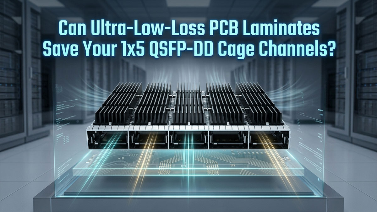
Why Outer Ports of the 1x5 QSFP-DD Cage Suffer Higher Trace Losses
In high-density data center deployments, standard 19-inch racks force five 800G optical ports to sit side-by-side along the crowded front panel. Because the switch ASIC sits centered on the motherboard, differential pairs routed to the peripheral slots of the 1x5 QSFP-DD cage must travel significantly longer distances across the board.
These outer runs often stretch beyond 8 inches, winding past dense power rails and cooling channels inside the tight 1U enclosure. At 28 GHz Nyquist frequencies, this added distance causes severe dielectric attenuation on outer lanes, threatening to break 800G signal integrity while center channels easily pass.
How Traditional Laminates Choke Channels Behind the 1x5 QSFP-DD Cage
Legacy low-loss substrates like Megtron 6 served 400G deployments well, but they quickly hit physical limits under 112G PAM4 signaling. When routing high-speed channels into the dense pin footprint of a 1x5 QSFP-DD cage, traditional resin systems exhibit excessive dissipation factors that rapidly exhaust the 16 dB IEEE 802.3ck budget. This material breakdown creates clear physical obstacles for high-density 1U switches:
- Excessive trace attenuation: Conventional laminates bleed between 1.2 and 1.4 dB per inch at 28 GHz, causing long outer traces to fail link margins.
- Severe eye closure: Higher dielectric dissipation rounds off the ultrashort rise times needed by PAM4, leaving insufficient eye height for host equalizers.
- Thermal degradation under load: High rack temperatures in dense 1U enclosures degrade traditional laminate properties, driving insertion loss even higher during peak data center traffic.
Extending Reach to the 1x5 QSFP-DD Cage Using Megtron 7 and 8
Hyperscale data centers overcome these trace length disparities by adopting ultra-low-loss materials like Megtron 7 and Megtron 8. These advanced laminates cut the material dissipation factor down to roughly 0.0015 to 0.0020, dropping high-frequency attenuation to between 0.7 and 0.9 dB per inch at 28 GHz.
This recovered signal margin directly rescues the peripheral channels of the 1x5 QSFP-DD cage in high-density builds. By flattening attenuation differences across all five ports, elite laminates allow hardware architects to close 800G links using standard planar PCB manufacturing methods.
Preserving 100-Ohm Impedance Matching at the Cage Footprint Interface
Deploying high-density 1U switches requires seamless electrical transitions where high-speed board traces terminate into the connector pins. The physical transition from the PCB laminate into the press-fit or surface-mount leads of a 1x5 QSFP-DD cage introduces sharp capacitive parasitics if the stackup geometry is mismatched.
Maintaining a strict 100-ohm differential impedance across this physical boundary requires sub-micron copper surface roughness and tightly controlled dielectric thickness. Tuning anti-pad clearances and specifying spread glass fabrics prevents impedance dips at the interface, ensuring clean 112G PAM4 transmission across all five front-panel ports.
❇️ How Thermal Stress Threatens 1x5 QSFP-DD Cage Signal Margins in a 1U Chassis
Even when ultra-low-loss laminates recover electrical insertion loss on paper, extreme heat inside a compact 1U enclosure can silently dismantle those high-frequency gains. As five high-speed transceivers operate side by side in a 1x5 QSFP-DD cage, thermal dissipation and electrical performance become inextricably linked.
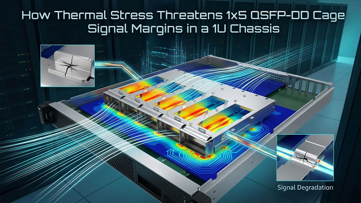
The Thermal Realities of Five 15W to 20W Optical Transceivers
Deploying five 800G optical modules within a single ganged housing concentrates an enormous amount of power in a tiny front-panel footprint. Modern 800G transceivers running onboard DSP engines typically draw between 15W and 20W per port. As a result, thermal management shifts from a secondary cooling task into an immediate electrical reliability challenge:
- Massive power density: When fully loaded, a 1x5 QSFP-DD cage dumps nearly 100W of localized heat across a narrow horizontal span of less than five inches.
- Severe space limits: The 44.45mm height of a 1U chassis leaves minimal vertical clearance for tall passive heatsinks or expansive copper heat pipes.
- Airflow impedance: Tightly grouped transceiver bodies restrict intake air passages, making it difficult to sweep hot boundary layers away from internal electrical contacts.
How Localized Heat Pockets Elevate PCB Dielectric Loss
Intense thermal concentration does not stay isolated within the metal cage; it conducts directly into the underlying host circuit board. High temperatures degrade the microscopic electromagnetic properties of the substrate, triggering severe signal degradation across high-speed channels. Hardware architects must actively mitigate several high-temperature failure modes:
- Rising dissipation factors: As PCB temperatures climb toward 85°C or higher, the dielectric loss tangent (Df) increases, burning through several extra decibels of insertion loss.
- Eye margin degradation: Elevated heat raises thermal noise and accelerates driver jitter, causing already narrow 112G PAM4 eye openings to shrink or close entirely.
- Localized dielectric shifts: Uneven heat gradients across the 1x5 QSFP-DD cage footprint alter the dielectric constant (Dk), creating phase delays and channel-to-channel timing skew.
Custom Heat Sinks for Thermal-Electrical Co-Optimization
Because standard 1U height restrictions prevent the use of bulky cooling blocks, mechanical designers must optimize the cage structure itself. High-performance 1x5 QSFP-DD cage assemblies incorporate multi-segmented riding heat sinks held in place by precision spring clips. These customized components provide three distinct thermal advantages:
- Direct thermal conduction: Precision-machined baseplates maintain continuous mechanical pressure against transceiver top covers to maximize thermal interface transfer.
- Aerodynamic fin design: Low-profile pin-fin or straight-fin geometries minimize static airflow resistance while expanding total convective surface area in shallow 1U spaces.
- Signal trace protection: Rapidly siphoning heat off the module tops prevents thermal saturation of the host PCB, preserving essential 112G PAM4 transmission margins.
Optimizing 1U Airflow Channels and Static Pressure Behind the Cage
Relying solely on local riding heat sinks is insufficient if the cooling air inside the 1.75-inch chassis becomes stagnant. In a dense 1U switch enclosure, hardware architects must deploy high-speed counter-rotating fan trays capable of delivering substantial static pressure across the front panel.
Channeling direct, uninterrupted airflow through the vented metal walls of the 1x5 QSFP-DD cage rapidly evacuates thermal boundary layers before heat soaks into the host PCB. This aggressive front-to-back cooling regime stabilizes the dielectric substrate under continuous 800G traffic, ensuring channel loss and PAM4 eye openings remain fully compliant with IEEE standards.
❇️ Why Hardware Architects Trust the LINK-PP 1x5 QSFP-DD Cage for 1U 800G Builds
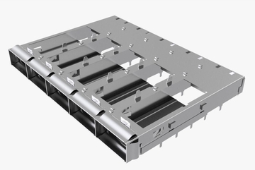
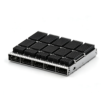
Successfully executing a high-density 1U switch layout requires interconnect hardware that balances tight electrical tolerances with real-world airflow demands. The LINK-PP 1x5 QSFP-DD Cage provides hyperscale system architects with versatile physical-layer solutions, offering both pre-installed riding heatsink assemblies for standard chassis and open-top variants without heatsinks for custom ducting. This flexibility allows hardware teams to tailor front-panel airflow without sacrificing high-frequency channel margins.

Optimized 112G High-Speed Contact Geometries for Minimal Crosstalk
Meeting strict IEEE 802.3ck limits requires clean electromagnetic containment across the entire connector housing. Inside the 1x5 QSFP-DD cage, precision-formed ground blades isolate individual differential pairs directly at the contact interface. This dedicated internal shielding suppresses energy leakage between adjacent transmit and receive lines, keeping near-end crosstalk low even when all five ports run at full line rates.
Miniaturized press-fit pin profiles significantly reduce capacitive discontinuities at the host board boundary, maintaining uniform 100-ohm differential impedance. By preventing noisy aggressor lanes from distorting neighboring signals, this optimized contact geometry delivers clear PAM4 eye openings across all forty high-speed lanes. Consequently, switch designers gain the electrical headroom needed to route long traces across crowded 1U motherboards.
Advanced Riding Heat Sink Options for Dense 1U Thermal Dissipation
For platforms relying on standard front-to-back chassis fans, LINK-PP provides factory-installed riding heatsinks secured by precision spring clips. These low-profile thermal solutions maintain firm contact with the top covers of inserted optical transceivers, drawing concentrated heat away from internal contacts and the motherboard beneath.
Operating five high-power optics inside a single 1x5 QSFP-DD cage can generate up to 100W across a narrow front-panel opening. The integrated heatsink fins maximize surface exposure within the slim 44.45 mm height, allowing intake fans to sweep heat away before it can soak into the circuit board. This continuous heat removal prevents high temperatures from degrading PCB dielectric performance during sustained data center traffic.
Rigorous High-Frequency Signal Integrity Verification
Before rolling out high-density hardware across production server clusters, engineering teams need proof that ports will run error-free under real network loads. The 1x5 QSFP-DD cage undergoes rigorous multi-channel validation using active 800G optical transceivers and live switch host silicon.
Verification focuses on real-world operating conditions, transmitting high-bandwidth traffic across all five ports simultaneously to simulate peak data center activity. Technicians continuously monitor pre-FEC bit error rates and PAM4 eye openings to confirm that neighboring channels cause no packet drops or signal flutter. This system-level validation proves that the cage maintains robust channel margins, giving network operators complete confidence during large-scale data center deployment.
❇️ Conclusion: Best Practices for Deploying the 1x5 QSFP-DD Cage in 1U 800G Networks

Deploying an 800G switching platform in a compact 1U chassis requires hardware architects to balance severe physical constraints against rigorous high-frequency electrical budgets. By pairing ultra-low-loss PCB materials with a high-performance 1x5 QSFP-DD cage, engineering teams can conquer 28 GHz insertion loss and keep multi-port PAM4 channels fully compliant.
Successfully transitioning from initial board layout to reliable, high-volume data center deployment relies on several proven system-level guidelines:
- Budget insertion loss strictly: Reserve sufficient attenuation margin across outer PCB traces to absorb high-temperature substrate losses and trace length discrepancies between inner and peripheral channels.
- Control front-panel thermal saturation: Combine riding heatsinks with high-static-pressure cooling fans to rapidly evacuate optical module heat before it elevates host board dielectric loss around the 1x5 QSFP-DD cage.
- Prioritize connector pinout isolation: Enforce solid continuous ground planes beneath connector footprints and utilize internal shielding blades to suppress multi-channel near-end crosstalk across tightly spaced 112G lanes.
Overcoming the 800G front-panel density bottleneck does not require sacrificing link stability or board reliability. With the right thermal management strategy, tight impedance control, and thoroughly validated interconnect hardware, a high-density 1U architecture reliably delivers the bandwidth scale modern data centers demand.
Equip your dense 1U switch builds with dependable 112G PAM4 connectivity by sourcing the 1x5 QSFP-DD cage directly from the LINK-PP Official Store to request evaluation samples and accelerate your data center hardware deployment.