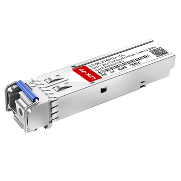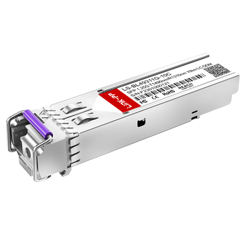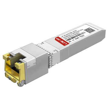
In modern networking, establishing a direct SFP to SFP connection is a fundamental method for linking high-speed devices. Often referred to as a "back-to-back" configuration, this setup involves a direct optical link between two SFP ports, bypassing complex intermediary hardware. Whether used for switch-to-switch stacking, laboratory testing, or establishing temporary high bandwidth links, understanding the underlying logic of these connections is essential for maintaining a stable and efficient network fabric.
Successful SFP to SFP integration relies on more than just physical plugging; it requires precise alignment of optical parameters and hardware protocols. From the TX-to-RX cross-over logic of LC cabling to the critical matching of wavelengths and fiber types, every layer of the connection must be synchronized. By mastering the physical basics and diagnostic monitoring (DDM), network engineers can optimize link budgets and ensure reliable data transmission across 1G, 10G, and higher-speed architectures.
🔆 What Is an SFP to SFP Back-to-Back Connection
An SFP to SFP back-to-back connection refers to a direct networking configuration where two SFP optical transceiver modules are linked via a fiber optic cable without any intervening active equipment. This setup serves as a fundamental building block for high-speed data transmission, providing a dedicated point-to-point channel between two hardware interfaces.
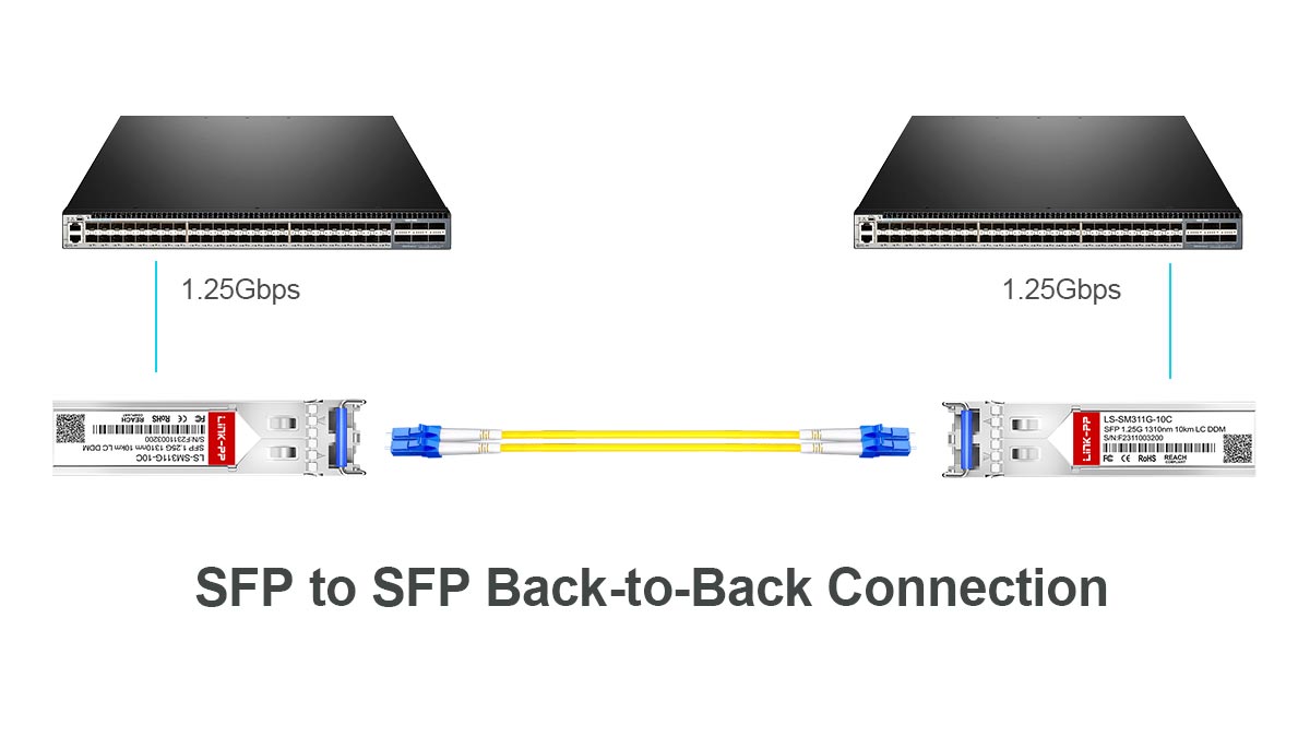
Definition: Direct Optical Link Between Two SFP Ports
At its core, an SFP to SFP connection is a hardware-level link established by inserting transceiver modules into the SFP slots of two different devices — such as switches, routers, or servers — and connecting them with the appropriate fiber patch cord. This creates a seamless optical path that allows electrical signals from one host device to be converted into light, transmitted, and then converted back into electrical data at the receiving end.
Unlike complex network topologies that involve multiple hops through mid-span repeaters or amplifiers, the back-to-back method is defined by its simplicity and low latency. It is the most direct way to facilitate communication between two Ethernet or Fibre Channel ports, relying entirely on the internal logic of the transceivers to manage signal integrity.
How Back-to-Back Connections Work in Practice
In a practical environment, the "back-to-back" logic requires careful alignment of the transmit (TX) and receive (RX) paths. When two SFP modules are connected, the fiber cable must ensure that the light output from Port A’s transmitter reaches Port B’s receiver, and vice-versa. This is typically achieved using a "crossover" fiber jumper, which prevents the two transmitters from firing into each other, a mistake that would result in a link failure.
Once the physical connection is made, the host devices engage in a handshake process. The SFPs exchange basic signals to confirm that a valid optical carrier is present. If the wavelengths, speeds, and fiber types are compatible, the Link Layer status changes to "Up," and the devices begin synchronizing their clocks to allow for the error-free exchange of data packets.
Common Use Cases for SFP to SFP Connections
One of the most frequent applications of SFP to SFP connectivity is in switch-to-switch cascading. In data centers or enterprise MDF/IDF closets, back-to-back fiber links are used to stack switches or create high-speed uplinks, expanding the network's port density and bandwidth. Because it supports distances ranging from a few meters to tens of kilometers, it is a versatile solution for both localized and campus-wide distribution.
Additionally, this configuration is a staple in lab testing and troubleshooting. Engineers often connect two SFPs back-to-back in a controlled environment to validate hardware performance, test software configurations, or simulate long-distance links using attenuators. It is also the go-to method for temporary links, such as setting up emergency data recovery sites or providing high-speed access during events where a permanent infrastructure is not yet available.
🔆 Physical Basics of SFP to SFP Connections
The physical layer is the foundation of any SFP to SFP link, encompassing the mechanical and optical requirements necessary for signal integrity. Establishing a successful connection requires a precise understanding of how light travels through fiber media and the hardware interfaces that facilitate this exchange.
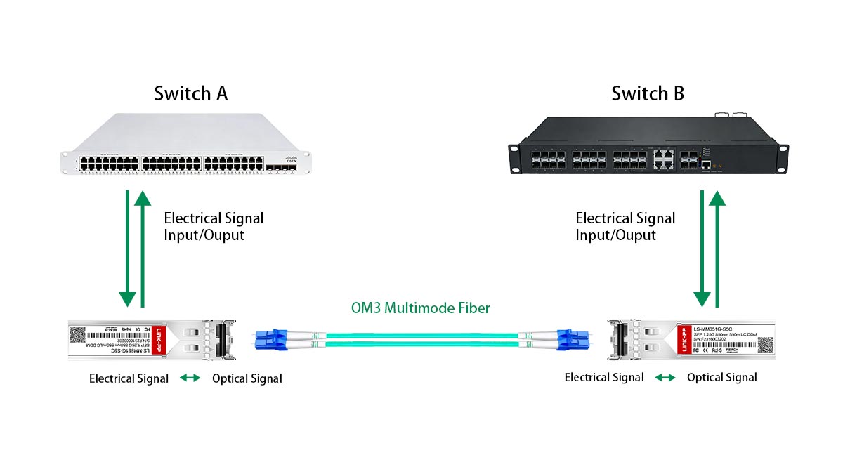
TX-to-RX Cross-Over Logic Explained
In a standard dual-fiber SFP setup, communication relies on a transmit (TX) channel and a receive (RX) channel. For two SFPs to communicate, the "output" of the first module must align with the "input" of the second. This is known as cross-over logic, where the TX port of SFP A is connected to the RX port of SFP B, and vice versa.
Without this crossover, the link will remain down because both modules would be attempting to "talk" on the same strand while "listening" on the other. While some modern systems support auto-MDIX for copper, optical links strictly require the correct physical orientation of the fiber pair, often managed by the polarity of the LC duplex connector.
Dual-Fiber LC Interface and Cabling Types
The LC (Lucent Connector) is the industry-standard interface for SFP modules due to its small form factor and high-density capabilities. These connectors typically feature a "push-pull" latching mechanism that ensures a secure physical seat within the SFP transceiver, minimizing insertion loss and protecting the delicate glass ferrule.
When selecting cables for SFP to SFP links, the most common choice is the duplex patch cord, which binds two fibers together to handle simultaneous bi-directional traffic. However, in specific scenarios, Simplex BiDi SFP modules may be used, which utilize a single fiber strand by employing different wavelengths for TX and RX, though these still require precise matching of the internal optical filters.
Single-Mode vs Multimode Fiber Selection
Choosing between single-mode fiber (SMF) and multimode fiber (MMF) is primarily determined by the distance of the link and the specific SFP modules in use. SMF utilizes a narrow core to transmit a single light path, making it ideal for long-range connectivity, whereas MMF uses a wider core that allows multiple light modes to propagate, which is cost-effective for short-range data center applications.
The following table summarizes the key technical differences between these two fiber types to help guide your selection:
| Feature | Single-Mode Fiber (SMF) | Multimode Fiber (MMF) |
| Core Diameter | 9µm | 50µm or 62.5µm |
| Wavelength | 1310nm / 1550nm | 850nm |
| Typical Distance | 10km to 80km+ | Up to 550m |
| Light Source | FP or DFB Laser | VCSEL Laser |
| Cost | Higher | Lower |
Direct Fiber Connection vs Patch Panel Deployment
In a direct fiber connection, a single patch cord links two SFP ports across a short distance, such as within the same rack. This method offers the lowest possible signal attenuation and is the simplest to troubleshoot. It is the preferred choice for high-speed stacking or connecting adjacent servers where cable management is straightforward.
Conversely, patch panel deployment introduces intermediate connection points to organize cabling across larger facilities. While this adds "interconnect loss" due to the extra adapters and jumpers, it provides the scalability and flexibility needed for structured cabling. When using patch panels for SFP to SFP links, engineers must account for the cumulative optical budget to ensure the signal remains within the receiver's sensitivity range.
🔆 How SFP to SFP Links Establish Connectivity
The transition from a physical fiber connection to a functional data link involves a sophisticated sequence of hardware signaling and logical synchronization. This process ensures that both SFP modules are not only physically present but also electrically and optically compatible to exchange bitstreams.
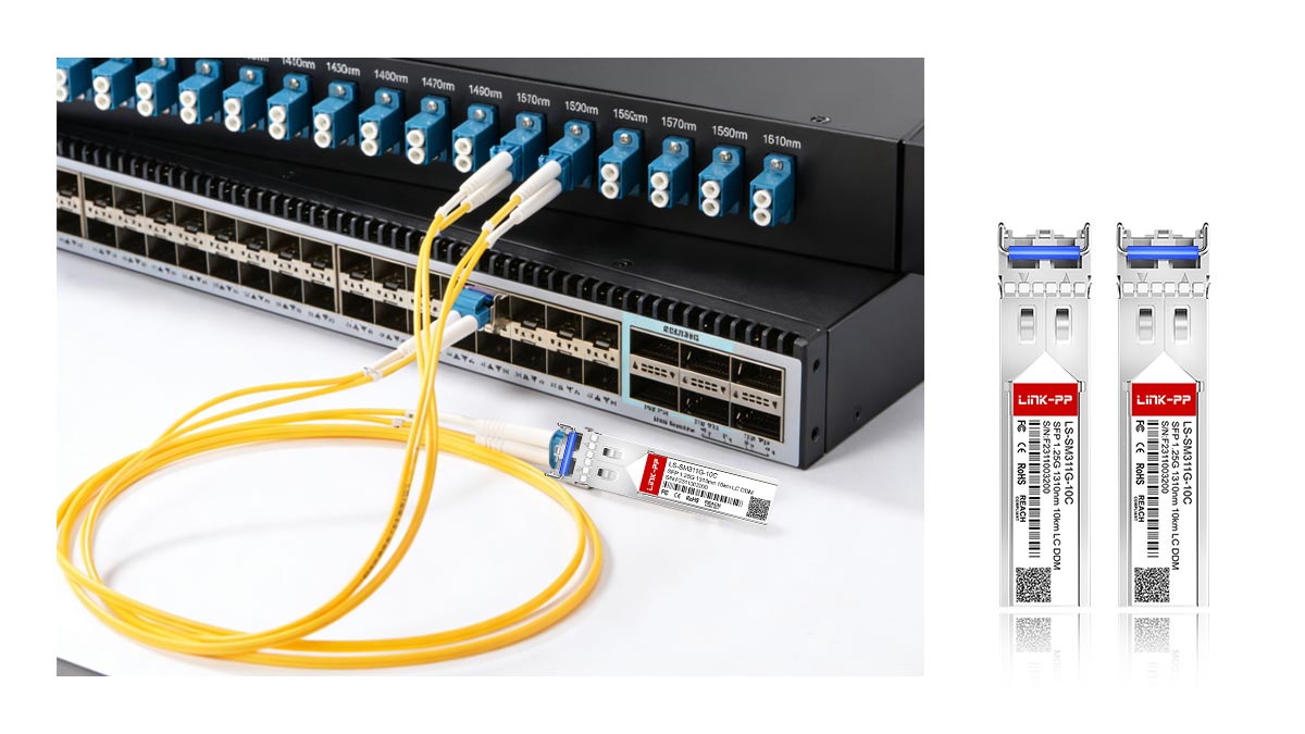
Link Initialization and Loss of Signal (LOS) Detection
The initialization process begins the moment an fiber optic SFP module is inserted and powered. The transceiver's internal logic immediately monitors the optical input via the loss of signal (LOS) pin. If the receiver detects an incoming optical power level above its designated threshold, the LOS signal is de-asserted, signaling to the host switch that a physical carrier is present.
If the fiber is broken or the remote SFP is powered down, the LOS remains active, preventing the host from attempting to send data into a "dark" link. This hardware-level detection is the first line of defense in link management, ensuring that higher-level protocols only engage when a valid physical connection is verified.
Auto-Negotiation vs Forced Speed Configuration
In standard 1G SFP connections, auto-negotiation is often used to synchronize link parameters like speed and duplex mode between the two endpoints. The devices exchange "fast link pulses" or specific code groups to agree on the highest mutually supported speed. However, in back-to-back SFP setups involving different vendors or older legacy gear, auto-negotiation can occasionally fail or lead to "port flapping."
For high-speed links like SFP+ 10G, SFP28 25G, or QSFP28 100G, auto-negotiation is often disabled in favor of forced speed configuration. Because these high-speed standards usually operate at a fixed rate, manually hard-coding the speed on both ports ensures a faster and more stable link-up process, eliminating the ambiguity of the negotiation phase.
Clock and Data Recovery (CDR) in High-Speed Links
As data rates climb into the gigabit range, maintaining signal timing becomes a significant challenge. Clock and data recovery (CDR) is a critical function within high-speed SFP+ and SFP28 modules that extracts timing information directly from the incoming data stream. Since there is no separate clock wire in fiber optics, the receiver must "reconstruct" the clock to accurately sample the high-speed optical pulses.
The CDR circuitry cleans up signal jitter and compensates for minor timing distortions caused by the fiber medium. In a back-to-back SFP connection, the quality of the CDR determines how well the system can tolerate signal degradation. If the CDR cannot lock onto the incoming frequency, the link will suffer from high bit error rates or fail to initialize entirely, even if the optical power is within the normal range.
🔆 Compatibility Considerations in SFP to SFP Connections
Compatibility is the most critical hurdle in ensuring a seamless SFP to SFP link, as it requires the synchronization of optical, physical, and software-coded parameters. Even if the hardware fits perfectly into the slot, a mismatch in wavelength, speed, or vendor-specific coding can prevent the link from initializing or cause intermittent performance issues.
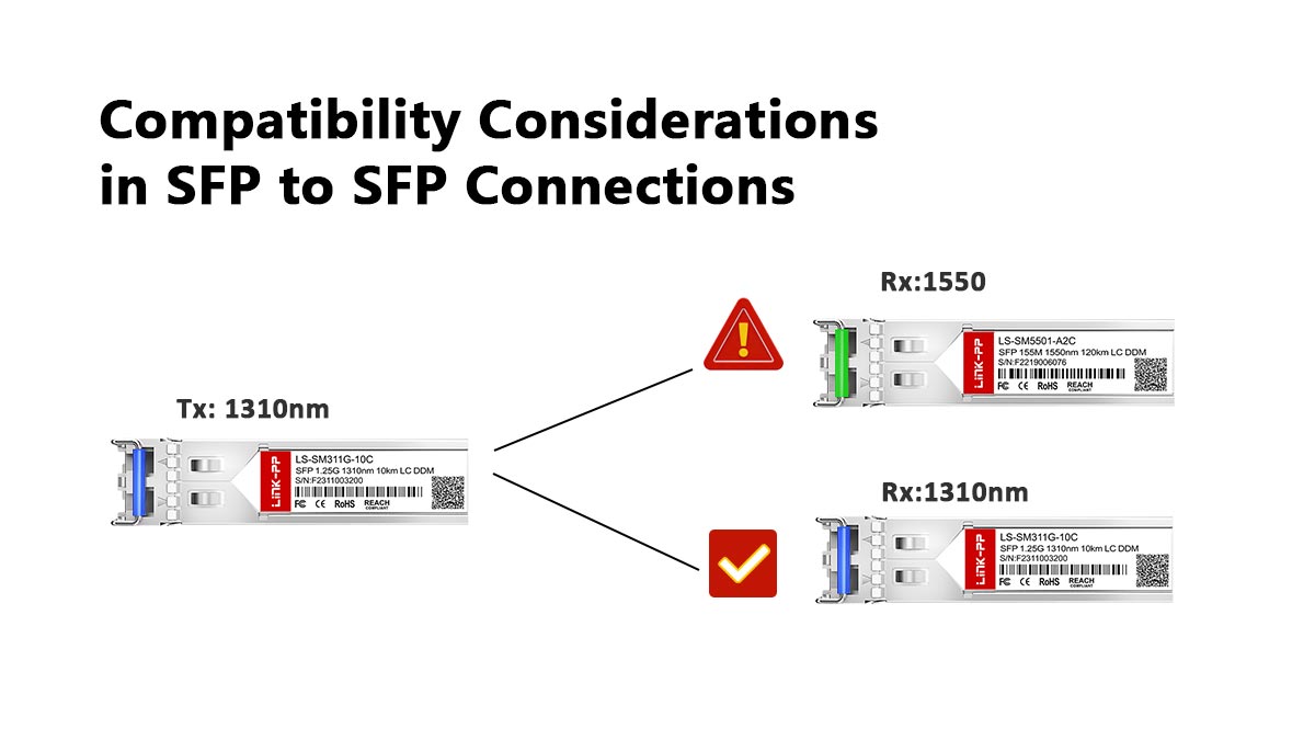
Wavelength Matching (850nm, 1310nm, 1550nm)
In a back-to-back configuration, both SFP transceivers must operate on matching wavelengths to "understand" each other. For instance, a multimode SFP typically uses an 850nm laser, while single mode transceivers utilize 1310nm or 1550nm. If one side transmits at 1310nm and the other expects 850nm, the receiver will be blind to the incoming signal, resulting in a total link failure.
Wavelength matching becomes even more complex with BiDi SFP modules, which use wavelength division multiplexing (WDM) to transmit and receive on a single strand. In these cases, you must use a complementary pair — such as a 1310nm-TX/1490nm-RX module (like GLC-BX-U) on one end and a 1490nm-TX/1310nm-RX module (like GLC-BX-D) on the other — to ensure the transmit frequency of one aligns perfectly with the receive frequency of the other.
Fiber Type Mismatch (SMF vs MMF Issues)
The physical medium must match the optical specifications of the SFP modules. Single-mode fiber (SMF) and multimode fiber (MMF) have vastly different core diameters, and mixing them in an SFP to SFP link leads to severe signal attenuation or "modal dispersion." Inserting an MMF patch cord between two SMF transceivers will cause the light to scatter, likely dropping the signal below the receiver's sensitivity threshold.
While some specialized mode conditioning cables exist to bridge certain gaps, the industry standard is to maintain strict uniformity. Using the wrong fiber type often results in a "link down" status or a high bit error rate (BER), as the light pulses become too distorted for the receiving SFP to accurately reconstruct the data.
Vendor Compatibility and Module Coding (EEPROM/Brand Lock)
Beyond the physics of light, many network equipment manufacturers implement "Vendor Lock-in" through the SFP's internal EEPROM. This small memory chip contains vendor-specific codes that the host switch checks upon insertion. If the code does not match the switch’s "approved list," the port may be administratively disabled, or the switch may trigger a "third-party transceiver" warning.
To ensure compatibility in an SFP to SFP setup involving different hardware brands, engineers must use "compatible" modules coded specifically for each respective host. This ensures that the I2C interface can properly communicate with the host OS, allowing for full access to diagnostic data and preventing software-level port shutdowns.
Speed and Protocol Compatibility (1G, 10G, 25G)
Speed mismatch is a common reason for link failure in back-to-back setups. Most SFP ports are designed for specific data rates; while some SFP+ ports (10G) are backward compatible with standard SFPs (1G), such as 407-BDCY, this is not a universal rule. If one end is locked at 10Gbps and the other is a legacy 1Gbps module, they will fail to synchronize their clock rates, and the link will remain inactive.
Furthermore, the underlying protocol must align. While Ethernet is the most common, SFPs are also used for Fibre Channel (storage) and OTN (telecom). An SFP designed strictly for 8G Fibre Channel SFP will not establish a link with an Ethernet-coded SFP, even if they share the same physical wavelength and fiber type, because the framing and encoding rules differ at the data link layer.
🔆 Distance Limitations and Optical Budgets for SFP to SFP
Managing the optical budget is vital for ensuring that the light signal is neither too weak to be detected nor too strong to damage the receiver. In an SFP to SFP setup, the distance limitation is governed by the balance between the transmitter's launch power and the receiver's sensitivity, accounting for all losses along the fiber path.

Calculating Link Loss and Attenuation Margins
Link loss calculation involves totaling the decibel (dB) loss from every component between the two SFP ports. This includes the inherent attenuation of the fiber cable per kilometer, connector insertion losses, and any losses from splices or patch panels. The total loss must be lower than the "optical power budget," which is the difference between the SFP’s minimum transmit power and its minimum receiver sensitivity.
Beyond the basic calculation, engineers must maintain an attenuation margin — typically around 2dB to 3dB. This safety buffer accounts for future fiber aging, potential repairs (splices), and environmental factors that might increase signal loss over time. If the calculated loss consumes the entire budget with no margin, the link may suffer from intermittent flapping or high bit error rates.
Using Fixed Attenuators for Short-Range Back-to-Back Tests
A common risk in direct SFP to SFP connections, especially with long-range transceivers, is receiver saturation. If you connect two high-power long-haul SFPs with a short 1-meter patch cord, the light intensity may exceed the receiver's "saturation point," potentially causing bit errors or permanent physical damage to the sensitive photodiode.
To mitigate this, fixed optical attenuators are used to artificially reduce the signal strength to a safe level. These small "male-to-female" LC adapters are inserted into the link to mimic the signal loss of a long-distance fiber run. In testing environments, utilizing a 5dB or 10dB attenuator ensures that the receiver operates within its optimal dynamic range during back-to-back hardware validation.
Dispersion Limits in Long-Haul Fiber Connectivity
While attenuation refers to the signal's strength, dispersion refers to the signal's "blurring." In long-haul SFP to SFP links, chromatic and modal dispersion can cause the light pulses to spread out as they travel, eventually overlapping with one another. This makes it impossible for the receiving SFP to distinguish between individual bits, even if the optical power is still technically sufficient.
Distance limitations are often dictated by these dispersion limits rather than just power loss, particularly at speeds of 10G and above. For example, standard ZR 10G SFP+ modules can reach 80km, but pushing beyond that without dispersion compensation technology results in a "closed eye" on the signal diagram, leading to a complete loss of data integrity.
Impact of Fiber Bend Radius on Optical Budget
The physical handling of the fiber cable significantly impacts the optical budget of an SFP to SFP connection. If a fiber patch cord is bent too sharply — exceeding its specified minimum bend radius — the light escapes from the glass core into the cladding. This phenomenon, known as macro-bending loss, can instantly add several decibels of unplanned attenuation to the link.
In tight rack environments or crowded cable trays, poor cable management often leads to "stealth" link failures where the SFPs appear functional, but the signal is weakened by physical stress on the cable. Using bend-insensitive fiber (BIF) or ensuring proper slack management is essential to keep the optical budget within its designed operating parameters.
🔆 Digital Diagnostics Monitoring (DDM) in SFP to SFP Setup
Digital diagnostics monitoring, also known as DOM (digital optical monitoring), is a critical feature that allows network administrators to view the real-time operating parameters of an SFP module. In an SFP to SFP back-to-back setup, DDM acts as a "window" into the physical layer, providing the telemetry data necessary to predict potential failures and ensure the link stays within its optical budget.
Real-Time Monitoring of Optical Output Power
The transmit (TX) power is the amount of light energy an SFP module launches into the fiber. By monitoring this value through DDM, you can verify if the laser is functioning correctly and consistent with its factory specifications.
- Laser Health Tracking: A significant drop in TX power over time often indicates that the laser diode is aging or failing, allowing for proactive replacement before a total link outage occurs.
- Stability Verification: Consistent output power ensures that the "source" of the SFP to SFP link is stable, ruling out the local transceiver as the cause of high error rates or signal fluctuations.
Tracking Receiver Sensitivity and Input Levels
Receiver (RX) power monitoring is perhaps the most vital metric in a back-to-back connection, as it measures the strength of the light arriving from the remote SFP. This value must fall within the specific "dynamic range" of the receiver — neither too weak to be lost in noise nor too strong to cause saturation.
- Attenuation Analysis: If the TX power at one end is high but the RX power at the other is low, DDM helps engineers instantly identify excessive loss in the fiber cable or connectors.
- Saturation Prevention: In short-range tests, DDM confirms if the RX power is too high (approaching the saturation point), signaling the need for an optical attenuator to protect the hardware.
Temperature and Voltage Threshold Alerts
SFPs are sensitive electronic devices that operate within specific thermal and electrical boundaries. DDM continuously tracks the internal temperature of the module and the supply voltage provided by the host switch.
- Thermal Management: SFPs generate heat during high-speed data transmission; DDM alerts the system if the temperature exceeds safe limits, which could lead to bit errors or permanent hardware damage.
- Power Supply Monitoring: Voltage monitoring ensures the host device is providing stable power to the transceiver, as voltage dips can lead to erratic laser performance and frequent link flapping.
Utilizing I2C Interface for EEPROM Data Access
All DDM data is communicated between the SFP module and the host switch via the I2C (Inter-Integrated Circuit) serial interface. This two-wire bus allows the host to read the transceiver's internal memory (EEPROM) without interrupting the high-speed data traffic.
Beyond real-time diagnostics, this interface provides access to static information such as the manufacturer’s name, part number, serial number, and date code. In a back-to-back setup, this I2C communication is what allows the network operating system to display the "Show Interface Transceiver" command outputs, making it the primary bridge between the physical hardware and the management software.
🔆 Bit Error Rate (BER) Standards for SFP to SFP Reliability
Bit error rate (BER) serves as the ultimate benchmark for measuring the quality and reliability of an SFP to SFP connection. It quantifies the percentage of bits that have been altered during transmission due to noise, interference, or distortion, directly reflecting the health of the underlying optical link.
The Importance of the 10⁻¹² BER Threshold
In the world of high-speed networking, the gold standard for optical transmission is a BER of 10⁻¹². This means that, statistically, only one bit error occurs for every one trillion bits transmitted. Maintaining this threshold is vital because higher error rates lead to frequent packet retransmissions, which degrade network throughput and increase latency, eventually making the link unusable for mission-critical data.
For an SFP to SFP back-to-back setup, achieving a 10⁻¹² BER indicates that the signal-to-noise ratio (SNR) is optimized and the receiver is accurately distinguishing between high and low light pulses. If the BER rises to 10⁻⁹ or higher, the link may appear "up" in the software, but users will experience significant performance drops and application-level timeouts.
Signal Integrity Challenges in Industrial Environments
Signal integrity in SFP to SFP links can be compromised when deployed in industrial or harsh environments. Electromagnetic interference (EMI) from heavy machinery, extreme temperature fluctuations, and physical vibrations can all introduce jitter into the high-speed data stream. While fiber is immune to electrical EMI, the SFP electronics and the host interface are not, potentially leading to increased bit errors.
Furthermore, industrial environments often involve "dirty" power grids. Fluctuations in the voltage supplied to the SFP modules can affect the precision of the laser driver, causing the optical pulses to become inconsistent. Proper shielding of the host equipment and ensuring stable thermal management are essential to protecting the link's BER in these challenging conditions.
Forward Error Correction (FEC) in High-Bandwidth SFP+ Links
As speeds advance from 10G to 25G and beyond, the physical margins for error become incredibly slim. To combat this, Forward error correction (FEC) is often implemented. FEC works by adding redundant "parity" bits to the data stream at the transmitting SFP; the receiving end uses these bits to detect and automatically correct a certain number of errors without needing a retransmission.
In an SFP to SFP connection, FEC effectively "lowers" the required optical signal quality, allowing a link with a poor raw BER (e.g., 10⁻⁵) to be corrected back to a clean 10⁻¹² at the protocol level. However, both SFPs and the host ports must support the same FEC algorithm (such as Firecode or RS-FEC) for this to work. If there is a mismatch in FEC settings, the link may fail to initialize or show a massive amount of uncorrectable errors.
Impact of Optical Return Loss (ORL) on Error Margins
Optical return loss (ORL) refers to the amount of light reflected back toward the source laser, usually caused by dirty connectors, poor splices, or glass-to-air gaps in the SFP to SFP path. High levels of reflected light can cause "feedback" into the transmitting laser, creating optical noise and instability that directly spikes the bit error rate.
Managing ORL is particularly important in high-speed, long-distance links where high-power lasers are used. To maintain healthy error margins, engineers must ensure that all fiber end-faces are polished to the correct specification (usually UPC or APC) and meticulously cleaned. Even a microscopic speck of dust on an SFP ferrule can create enough reflection to ruin the link's BER, even if the total power loss (attenuation) seems acceptable.
🔆 Common Troubleshooting Protocols for SFP to SFP Failure
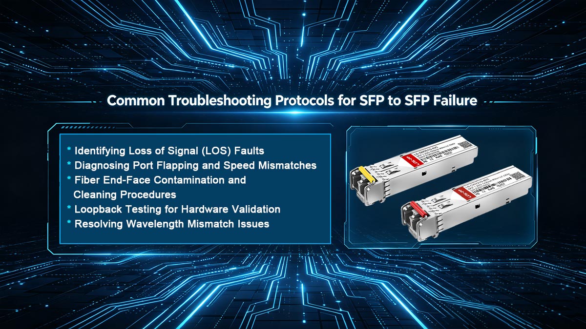
When an SFP to SFP link fails to initialize or experiences degraded performance, a systematic troubleshooting approach is required to isolate the fault. By moving from the physical layer up to the logical configuration, technicians can efficiently identify whether the issue lies with the transceivers, the fiber media, or the host settings.
Identifying Loss of Signal (LOS) Faults
A Loss of Signal (LOS) alarm is the most common indicator of a total link failure, signifying that the receiver is not detecting sufficient light. Troubleshooting this requires a step-by-step verification of the optical path:
- Physical Continuity: Check if the fiber patch cord is properly seated in the SFP ports or if there are visible breaks or sharp bends in the cable.
- Module Power: Verify that the SFP module is fully inserted into the host slot; sometimes a module may be "loose," preventing the electrical pins from making full contact with the switch backplane.
- TX Verification: Use the DDM interface to check if the remote SFP is actually transmitting light; if the TX power is "N/A" or "0," the remote laser may be disabled or faulty.
Diagnosing Port Flapping and Speed Mismatches
Port flapping — where the link status rapidly cycles between "Up" and "Down" — often points to marginal signal quality or a logical mismatch between the two endpoints.
- Speed/Duplex Lock: Ensure both ports are configured for the same speed (e.g., both at 10G). If one side is set to auto-negotiate and the other is forced, the link may struggle to remain stable.
- Link Budget Margins: Flapping can occur if the RX power is hovering exactly at the receiver's sensitivity threshold. A minor change in temperature or a slight vibration can cause the signal to drop just enough to break the link momentarily.
Fiber End-Face Contamination and Cleaning Procedures
Contaminated or dirty fiber connectors are a frequent but often overlooked cause of SFP to SFP failures. Dust, oil, or debris on the fiber end-face can significantly reduce optical signal quality and increase attenuation.
A proper cleaning process includes:
- Inspecting connectors using a fiber inspection scope.
- Cleaning with lint-free wipes and appropriate optical cleaning solutions.
- Avoiding repeated insertion of unclean connectors.
Regular cleaning and inspection practices are critical to maintaining consistent link performance.
Loopback Testing for Hardware Validation
If you suspect a hardware defect, loopback testing is the most definitive way to isolate the fault to a specific SFP module or host port.
- External Loopback: Connect a single SFP's TX port directly to its own RX port using a verified fiber jumper (ensure an attenuator is used for long-haul modules). If the port comes "Up," the SFP and the host port are functional, meaning the issue lies further down the fiber run.
- Internal Loopback: Many modern switches support a software-defined "internal loopback" that tests the electrical path within the switch without using light. This helps determine if the host's internal ASICs or SFP slots are failing.
Resolving Wavelength Mismatch Issues
A wavelength mismatch occurs when the two SFPs are operating on different parts of the optical spectrum. This is common when mixing up single-mode and multimode) equipment or when using BiDi SFPs without a matching pair.
In these cases, the DDM may show that both lasers are firing (TX is normal), but the receiving end shows a "link down" or very low RX power because the photodiode is not sensitive to the incoming wavelength. To resolve this, always verify that the part numbers on both SFP modules match the required specifications for the distance and fiber type being used.
🔆 Best Practices for Reliable SFP to SFP Connections
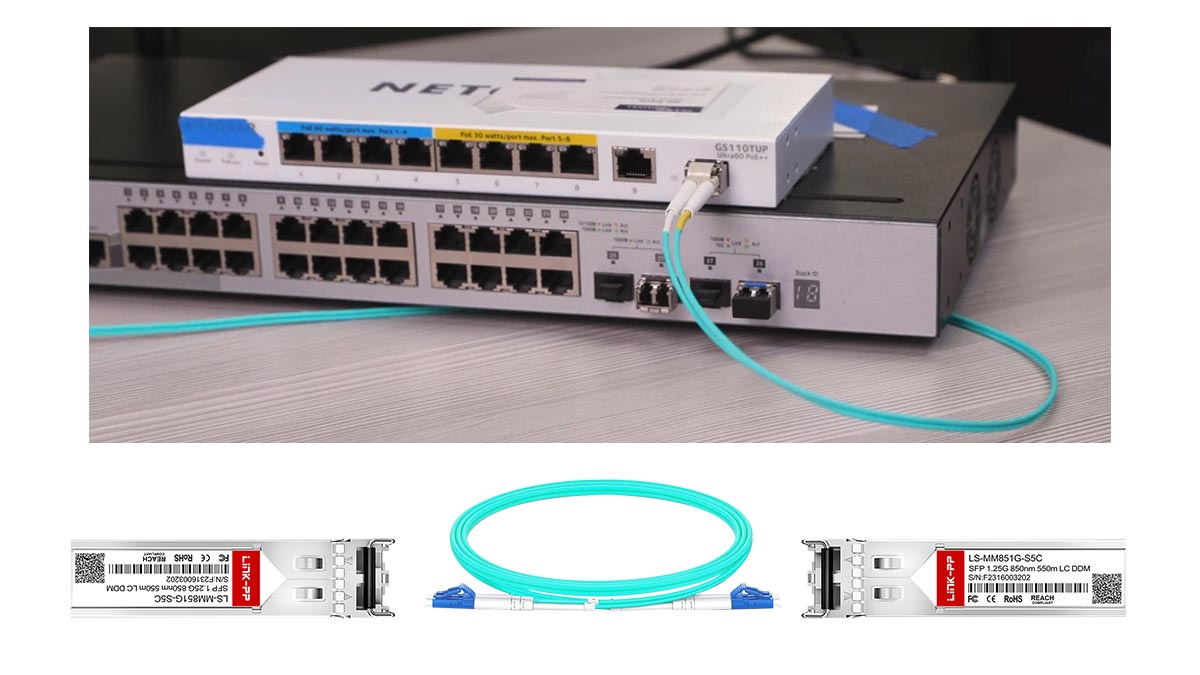
To ensure long-term stability in an SFP to SFP back-to-back setup, reliability must be designed into the link from the start. This involves adhering to strict fiber hygiene, such as cleaning every connector before insertion, and maintaining a healthy optical budget with at least a 2 - 3dB safety margin. Furthermore, consistently monitoring DDM telemetry allows for predictive maintenance, enabling you to identify shifting laser power or rising temperatures before they escalate into a Bit Error Rate (BER) crisis or a total link failure.
By aligning your hardware choices with industry standards — ensuring matching wavelengths, compatible speeds, and correct fiber types — you can eliminate the vast majority of connectivity issues. High-quality, vendor-compatible transceivers are the backbone of this architecture, providing the precision needed for low-latency and error-free data transmission. For high-performance networking solutions that guarantee seamless interoperability and reliability, explore the extensive range of optical transceiver modules available at the LINK-PP Official Store.