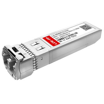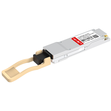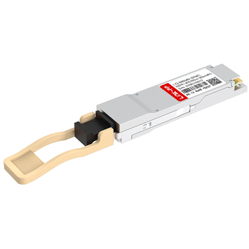
In modern 40G spine-leaf architectures, one of the most common deployment mistakes is not the transceiver itself—it is choosing the wrong QSFP-40G-SR4 MPO cable.
Many network engineers know that QSFP-40G-SR4 transceiver modules are designed for short-reach parallel multimode transmission, but the real challenge begins when the link must be physically patched between spine switches, leaf switches, patch panels, or structured fiber trunks. Questions quickly appear:
-
Should the SR4 link use a 12-fiber MPO or MTP cable?
-
Is Type B polarity required?
-
Do both ends need female connectors?
-
Why does the optical link stay down even when both QSFP optical transceivers are detected?
-
Can the same cable support 40G direct links and 4×10G breakout migration?
These are not minor purchasing details—they directly determine whether a 40G QSFP SR4 spine-leaf uplink comes online cleanly or fails during commissioning.
Because unlike LC duplex optics, QSFP-40G-SR4 uses 8 active fibers inside a 12-fiber MPO interface, where transmit and receive lanes must cross in a precise optical polarity path. A wrong MPO gender, incorrect polarity cassette, or mismatched trunk cable can create silent Layer 1 failures that are difficult to troubleshoot after rack installation.
This is why understanding QSFP-40G-SR4 MPO cable polarity mapping is now a critical part of designing high-density 40G data center backbones.
In this guide, we will break down:
-
how QSFP-40G-SR4 parallel optics actually use MPO fibers,
-
which MPO cable type is correct for spine-leaf interconnects,
-
how Type B polarity works in real deployments,
-
common cabling mistakes that cause 40G SR4 link failures,
-
and the most practical MPO solutions for direct 40G and breakout architectures.
If you are planning a 40G spine-to-leaf uplink, upgrading from 10G LC fiber, or trying to solve a persistent QSFP-40G-SR4 no-link issue, this article will give you the exact optical mapping logic before you buy the wrong cable.
✅ What Is a QSFP-40G-SR4 MPO Cable?
A QSFP-40G-SR4 MPO cable is a 12-fiber multimode MPO/MTP optical jumper used to carry the 8-lane parallel 40G signal between two SR4 QSFP+ modules.
To understand the term correctly, it helps to separate it into two parts:
-
QSFP-40G-SR4 = the 40 Gigabit short-reach optical transceiver module
-
MPO/MTP cable = the multi-fiber patch cable that carries the optical lanes between those transceivers
In simple terms, the transceiver generates the 40G optical signal, while the MPO cable provides the physical parallel fiber path that allows those signals to travel from one switch port to another.
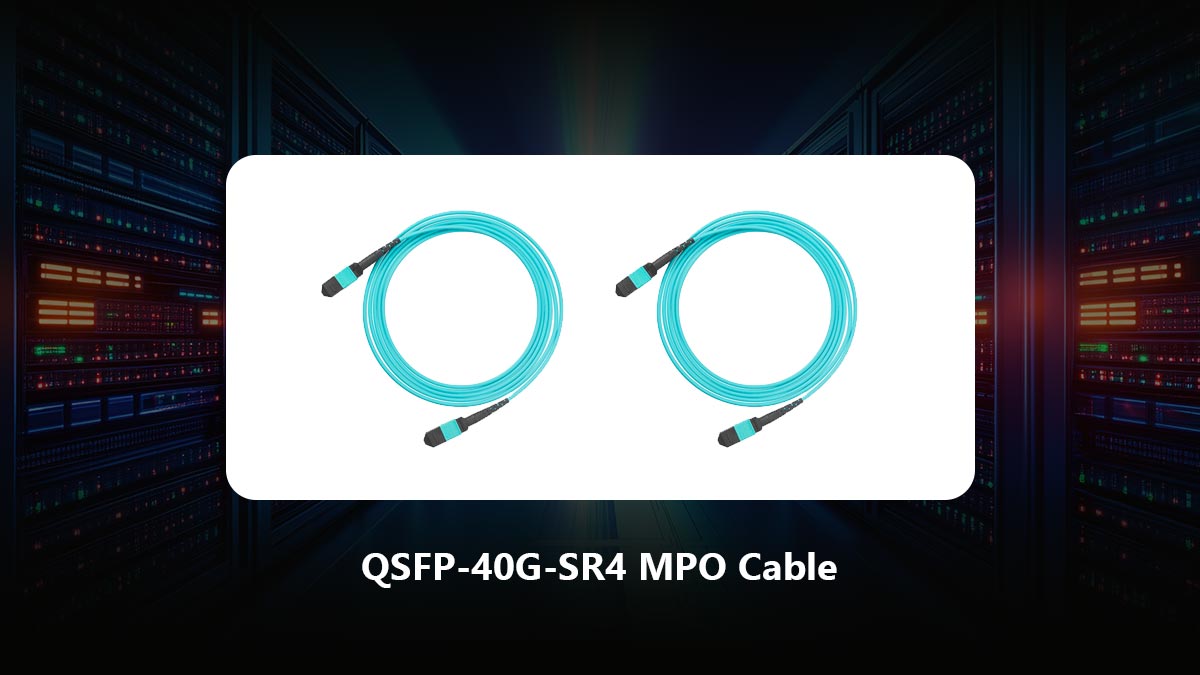
Unlike standard SFP+ optics that usually rely on duplex LC fiber, QSFP-40G-SR4 transceivers are built for parallel multimode transmission. Each module divides the 40G Ethernet channel into:
-
four 10Gbps transmit lanes
-
four 10Gbps receive lanes
These eight optical lanes are presented through a 12-fiber MPO/MTP interface, making the cable an essential part of the SR4 optical system rather than a simple passive jumper.
QSFP-40G-SR4 MPO Cable vs. Ordinary Fiber Patch Cable
This distinction is important because many buyers assume any multimode MPO jumper will work.
In reality, a QSFP-40G-SR4 optical path has stricter requirements than ordinary fiber patching because it depends on:
-
correct MPO polarity,
-
proper Tx/Rx lane crossover,
-
suitable MPO gender,
-
low insertion loss,
-
and full 40G parallel optical continuity.
A normal duplex LC cable only needs one transmit strand and one receive strand.
A QSFP-40G-SR4 MPO cable must carry eight simultaneous optical lanes in the correct order.
That is why SR4 MPO links are considered part of the optical channel engineering—not just part of cable management.
Why This Cable Is Widely Used in 40G Data Centers
QSFP-40G-SR4 MPO cabling became popular because it allows:
-
much higher port density,
-
simpler 40G switch uplinks,
-
efficient spine-leaf backbone design,
-
and easier migration from multiple 10G links into one aggregated 40G optical channel.
Instead of consuming four separate duplex LC pairs, one MPO cable can deliver all required lanes in a compact connector footprint.
This is especially valuable in:
-
spine-to-leaf aggregation,
-
top-of-rack uplinks,
-
core switch interconnects,
-
short-reach hyperscale patching.
As a result, the phrase “QSFP-40G-SR4 MPO cable” usually refers not only to the cable itself, but to the entire 40G short-reach parallel optics cabling solution.
✅ Why QSFP-40G-SR4 Requires Precise MPO Polarity in Spine-Leaf Networks
Unlike traditional duplex LC fiber links that use only one transmit strand and one receive strand, a QSFP-40G-SR4 MPO cable works through a parallel optics architecture. Inside each QSFP-40G-SR4 transceiver, the 40G signal is divided into four independent 10Gbps transmit lanes and four independent 10Gbps receive lanes. These eight optical lanes are routed through the center positions of a 12-fiber MPO/MTP connector, while the remaining four fiber positions stay unused in standard SR4 applications.
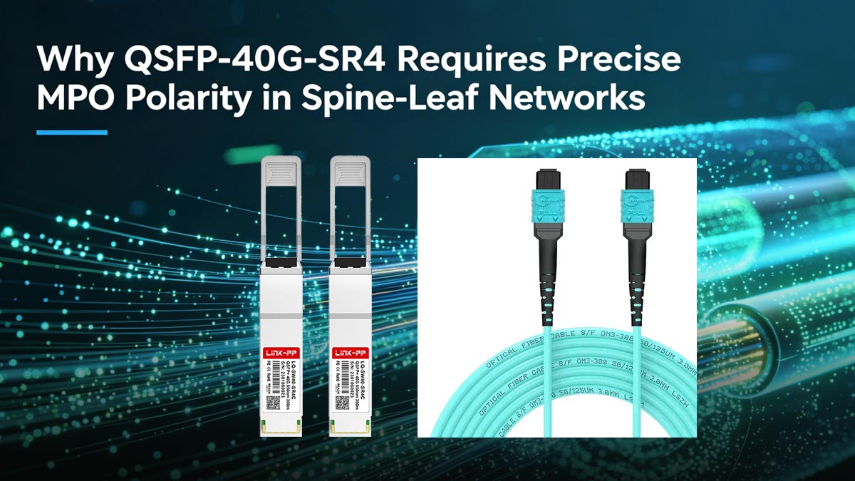
This means a QSFP-40G-SR4 link is not simply “fiber plugged into fiber.”
It is a lane-to-lane optical mapping system.
If even one transmit lane is mapped back into another transmit lane—or one receive lane into another receive lane—the link will not establish proper optical communication, even though:
-
both QSFP modules are inserted correctly,
-
DOM readings may appear normal,
-
and the switch ports may still recognize the transceivers.
That is why many 40G spine-leaf installations experience a frustrating “module detected but no link up” condition: the hardware is functional, but the MPO polarity path is wrong.
Cisco QSFP-40G-SR4 optical specification confirms that SR4 optics use parallel multimode fiber with an MPO interface, requiring the transmit array on one module to land precisely on the receive array of the opposite module. This is fundamentally different from duplex LC optics, where polarity correction is far simpler.
The Hidden Complexity: QSFP-40G-SR4 Uses 8 Active Fibers in a 12-Fiber MPO Path
A major reason users order the wrong cable is that the connector physically looks simple, but internally the signal path is not.
A standard QSFP-40G-SR4 transceiver typically uses:
-
Fiber 1–4 = Transmit lanes (Tx1–Tx4)
-
Fiber 5–8 = unused center crossover depending on numbering convention
-
Fiber 9–12 = Receive lanes (Rx1–Rx4)
In practical cabling terms, the transmit bank from the spine switch must land on the receive bank of the leaf switch, and vice versa.
This requires the MPO trunk to perform an optical inversion—commonly achieved by a Type B polarity MPO cable.
Without that polarity flip:
-
Tx aligns to Tx
-
Rx aligns to Rx
-
optical power exists
-
but Ethernet framing never initializes
This is exactly why network engineers often report: “Both SR4 modules are recognized, light is present, but the 40G port stays down.”
That symptom is usually not a transceiver failure.
It is a polarity mapping failure inside the MPO path.
Why Spine-Leaf Topology Makes Polarity Errors More Common
In a simple lab setup, two QSFP-40G-SR4 modules may connect directly with one MPO jumper and come online quickly.
But real spine-leaf networks rarely use such a clean point-to-point path.
A typical enterprise or hyperscale 40G uplink may include:
-
spine switch SR4 optic
-
front MPO patch cord
-
MPO cassette or patch panel
-
backbone MPO trunk
-
rear patch panel
-
leaf switch MPO jumper
-
leaf SR4 optic
Every additional mating point introduces one more opportunity for:
-
polarity inversion,
-
key-up/key-down mismatch,
-
male/female pin conflict,
-
cassette crossover confusion,
-
or accidental Type A / Type B substitution.
Because SR4 depends on eight parallel lanes working simultaneously, a single mapping inconsistency can collapse the entire 40G channel.
This is why MPO polarity planning is far more critical in spine-leaf structured cabling than in direct top-of-rack patching.
The Most Common Real-World SR4 Deployment Failure
Across engineering forums and deployment case studies, the most repeated failure pattern is: the installer assumes any MPO-12 multimode jumper will work.
But in reality, QSFP-40G-SR4 normally requires:
-
correct MPO gender compatibility,
-
OM3/OM4 multimode fiber,
-
12-fiber path continuity,
-
and most importantly, polarity that crosses Tx to Rx.
Using the wrong trunk often leads to:
-
link flapping,
-
no optical negotiation,
-
intermittent CRC errors,
-
or complete Layer 1 down status after rack integration.
This is why experienced data center designers do not treat the QSFP-40G-SR4 MPO cable as a passive accessory.
They treat it as part of the optical channel design.
For every QSFP-40G-SR4 spine-leaf uplink, the real objective is not simply:
“connect two 40G ports.”
The real objective is:
“ensure all four transmit lanes from one SR4 optic arrive on the four receive lanes of the opposite SR4 optic through a fully polarity-correct MPO path.”
Once this principle is understood, cable selection becomes much easier—and many expensive commissioning errors can be avoided before installation.
✅ How to Choose the Correct MPO Cable Type for QSFP-40G-SR4 Links
After understanding that QSFP-40G-SR4 depends on exact Tx-to-Rx lane crossover, the next question becomes the one that determines whether your 40G link will work on day one: Which MPO cable should actually be used between two QSFP-40G-SR4 transceivers?
This is where many buyers make an expensive mistake.
Because searching “MPO cable” online returns dozens of options:
-
MPO-8
-
MPO-12
-
Type A
-
Type B
-
Type C
-
male
-
female
-
OM3
-
OM4
-
elite loss
-
trunk
-
harness
-
cassette-compatible jumpers
Yet only a very specific combination is correct for most QSFP-40G-SR4 spine-leaf direct links.
Cisco-compatible SR4 deployment references and multiple field engineers consistently point to the same baseline: a 12-fiber multimode MPO/MTP cable with Type B polarity is the standard direct-connect solution for QSFP-40G-SR4 optics.
1. Start With the Fiber Count: MPO-12 Is the Standard SR4 Optical Path
Although QSFP-40G-SR4 only uses 8 active fibers for four transmit and four receive lanes, the physical optical interface on the module is built around a 12-fiber MPO/MTP connector standard.
That means for normal switch-to-switch SR4 connectivity, the safest and most universally compatible selection is: MPO-12 / MTP-12 multimode patch cable
This is the cable architecture expected by most Cisco-compatible, MSA-compatible, and third-party SR4 optics.
Many engineers ask whether an MPO-8 cable is enough.
In theory, yes, only eight fibers carry traffic.
In practice:
-
MPO-12 is the mainstream stocked format,
-
patch panel ecosystems are built around MPO-12,
-
transceiver mechanical alignment expects the 12-fiber footprint,
-
and most enterprise SR4 documentation assumes MPO-12 continuity.
So for procurement simplicity and interoperability: choose MPO-12 first unless your cabling architecture is specifically engineered otherwise.
2. The Most Important Decision: Type B Polarity, Not Type A
This is the step that causes the highest percentage of 40G SR4 no-link tickets.
There are three common MPO polarity methods:
-
Type A = straight through
-
Type B = full reversed / rollover
-
Type C = pair flipped
For a direct QSFP-40G-SR4 to QSFP-40G-SR4 optical channel, industry practice overwhelmingly uses: Type B MPO polarity
Why?
Because Type B reverses the fiber positions end-to-end:
-
Fiber 1 lands on Fiber 12
-
Fiber 2 lands on Fiber 11
-
Fiber 3 lands on Fiber 10
-
and so on
That reversal is what moves the transmit laser bank of one SR4 optic onto the receive detector bank of the opposite SR4 optic.
Reddit deployment discussions show this is the exact issue many installers discover only after a “notconnect” port state appears—Type A patch cords often leave Tx talking to Tx.
So if the link is: transceiver ↔ transceiver
then the default purchasing rule is: one Type B MPO trunk in the optical path.
3. Connector Gender: Know Whether Your SR4 Module Is Male or Female
This part is more confusing because vendor listings describe it differently.
Some SR4 optics are sold as:
-
MPO female receptacle (no guide pins)
while others are described as:
-
MTP male interface (guide pins inside transceiver)
What matters is not the wording on random reseller pages.
What matters is: the cable connector must mate physically with the optic connector pin structure.
Across Cisco community discussions and engineer recommendations, the most common direct SR4 jumper recommendation is: female-to-female Type B MPO/MTP patch cable for optic-to-optic links
However, always verify whether your specific transceiver has:
-
pinned male optic interface, or
-
unpinned female optic interface
before ordering in volume.
Because a polarity-correct cable with the wrong gender still creates a dead install.
4. OM3 or OM4? Choose Based on Real Spine-Leaf Distance
Since QSFP-40G-SR4 is a multimode 850nm VCSEL optic, the MPO cable also needs to match multimode specifications.
Standard recommendations are:
-
OM3 MMF = up to 100m
-
OM4 MMF = up to 150m
for compliant SR4 operation.
For short same-row or same-rack spine-leaf uplinks, OM3 is often enough.
But modern data center designers increasingly choose OM4 because:
-
insertion loss margins are better,
-
patch panel additions are more forgiving,
-
future migration to higher-density optics becomes easier.
So unless the deployment is cost-compressed and very short: OM4 Type B MPO-12 is usually the safer long-term buy.
5. Direct Link vs Structured Cabling: The Rule Changes Slightly
If you are connecting: QSFP-40G-SR4 directly to QSFP-40G-SR4
you normally use: 1 × Type B MPO-12 multimode patch cable
But if your spine-leaf architecture includes:
-
front patch cords,
-
rear trunks,
-
cassette modules,
-
cross-connect fields,
then polarity planning becomes an end-to-end channel calculation.
Experienced engineers often summarize it this way: you need an odd number of Type B inversions in the total optical path to preserve Tx-to-Rx crossover.
That is why many structured cabling installations fail even when every individual jumper “looks correct.”
The cable is only correct if the entire channel is polarity-correct.
Quick Buyer Checklist: Correct QSFP-40G-SR4 MPO Cable Selection
Before ordering, confirm these five points:
✔ MPO-12 or MTP-12 format
✔ multimode OM3/OM4 fiber
✔ Type B polarity
✔ correct male/female mating structure
✔ direct link or structured path polarity accounted for
If any one of these is wrong, the SR4 uplink may stay dark even with perfectly healthy optics.
✅ QSFP-40G-SR4 MPO vs. LC Cable: Which One Should You Use?
When deploying 40G Ethernet, engineers often choose between two cabling paths:
-
QSFP-40G-SR4 with MPO/MTP parallel fiber
-
LC duplex fiber with BiDi or duplex-compatible 40G optics
Both can deliver a 40GbE uplink, but they are designed for different network conditions.
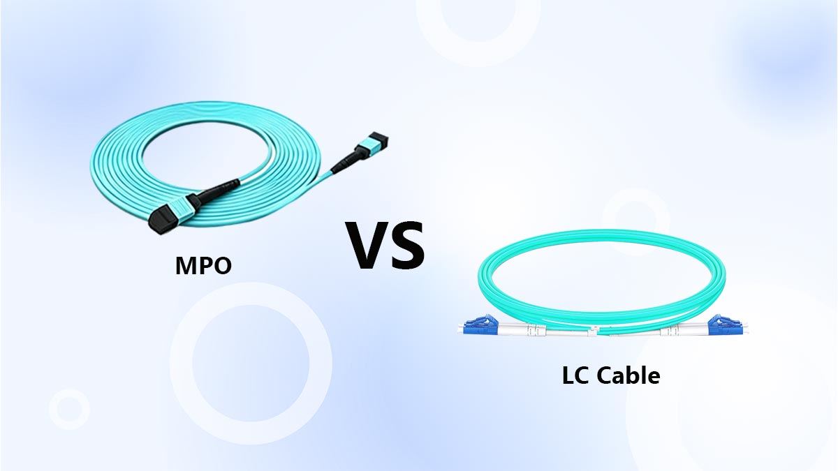
A QSFP-40G-SR4 MPO cable carries the 40G signal through 8 active fibers in one MPO-12 connector, making it ideal for parallel short-reach switching.
An LC duplex solution transmits 40G over only 2 fibers, usually through bidirectional or wavelength-multiplexed optics.
The practical difference is simple: MPO is built for new high-density 40G architectures, while LC is built for easier reuse of existing duplex fiber plants.
When QSFP-40G-SR4 MPO Cable Is the Better Choice
Use MPO cabling when:
-
building a new spine-leaf or switch-to-switch 40G backbone
-
requiring higher patch density
-
planning 40G to 4×10G breakout flexibility
-
aiming for lower SR4 transceiver cost per port
Because SR4 optics naturally operate as four parallel 10G lanes, MPO cabling is often the most scalable short-reach data center solution.
When LC Cable Makes More Sense
Use LC duplex cabling when:
-
existing infrastructure already uses LC multimode fiber
-
minimizing cabling reconstruction is a priority
-
field installation simplicity is more important than maximum density
-
only a few 40G point-to-point links are required
LC solutions reduce MPO polarity concerns and are generally easier for day-to-day maintenance.
QSFP-40G-SR4 MPO Cable vs. LC Cable Comparison
|
Comparison Item |
QSFP-40G-SR4 MPO Cable |
LC Duplex 40G Cable |
|---|---|---|
|
Optical architecture |
Parallel 8-lane fiber |
Duplex 2-fiber transmission |
|
Connector type |
MPO/MTP-12 |
LC duplex |
|
Fiber count used |
8 active fibers |
2 fibers |
|
Cabling density |
High |
Moderate |
|
Polarity complexity |
High |
Low |
|
40G to 4x10G breakout support |
Yes |
Limited |
|
Best for new 40G builds |
Excellent |
Moderate |
|
Best for existing LC infrastructure |
Poor |
Excellent |
|
Typical optic cost |
Lower |
Higher |
|
Installation simplicity |
Medium |
Easy |
Quick Decision Guide
Choose QSFP-40G-SR4 MPO cabling if your goal is: scalable, high-density, low-cost 40G short-reach deployment.
Choose LC duplex cabling if your goal is: fast migration using existing LC fiber with simpler patching.
In short, MPO is usually the better long-term option for modern spine-leaf fabrics, while LC is the practical choice for legacy fiber reuse.
✅ 40G to 4x10G Breakout and Migration Solutions
One of the biggest advantages of using a QSFP-40G-SR4 MPO cable is that it does not only support a standard 40G uplink—it also provides a practical migration path from legacy 10G infrastructure.
Because QSFP-40G-SR4 is internally built on four independent 10Gbps transmit lanes and four independent 10Gbps receive lanes, the module can operate in:
-
1 × 40G direct link mode, or
-
4 × 10G breakout mode
when the switch hardware and firmware support port breakout. Cisco specifically notes that QSFP-40G-SR4 supports 4x10G breakout interoperability, while QSFP-40G-SR4-S does not, which is an important distinction many buyers overlook.
This means one 40G QSFP+ port can be split into four separate 10G SFP+ optical channels without replacing the entire switch platform.
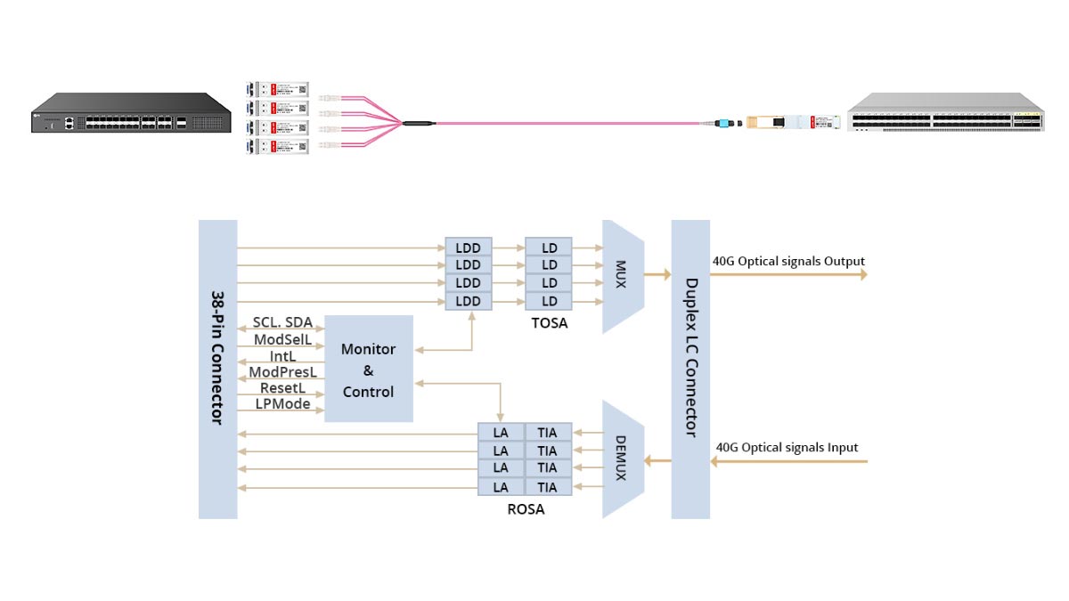
How the 40G to 4x10G Breakout Works
In breakout mode, the SR4 optic still transmits over the same 12-fiber MPO interface, but instead of landing on another QSFP-40G-SR4 module, the optical lanes are distributed through:
1 × MPO/MTP to 4 × duplex LC breakout harness
This harness maps the four SR4 optical lanes into:
-
LC Pair 1 = 10G Channel 1
-
LC Pair 2 = 10G Channel 2
-
LC Pair 3 = 10G Channel 3
-
LC Pair 4 = 10G Channel 4
Each LC pair then connects to an individual 10GBASE-SR SFP+ transceiver, such as a compatible SFP-10G-SR module.
Cisco’s optical breakout guide confirms that this 4x10G connectivity is achieved by an external 12-fiber parallel-to-duplex breakout cable specifically wired for QSFP-40G-SR4 lane mapping.
Why This Migration Path Is So Valuable
For many data centers, not every downstream device is ready for native 40G.
Common real-world situations include:
-
older servers still running 10G SFP+
-
firewalls with only 10G uplinks
-
storage appliances limited to 10GbE
-
staged leaf switch replacement projects
Instead of consuming four separate upstream switch ports, one SR4 breakout port can aggregate those four 10G links through a single 40G-capable QSFP slot.
This provides:
-
better port utilization,
-
simpler 10G-to-40G migration,
-
reduced uplink congestion,
-
and cleaner fiber management.
In practical terms: one QSFP-40G-SR4 MPO port can function as a bandwidth bridge between old 10G devices and a modern 40G spine.
✅ Common QSFP-40G-SR4 MPO Cable Problems and Fixes
Even when the correct QSFP-40G-SR4 transceivers are installed, many 40G links still fail because the MPO cable path is not configured correctly. In most cases, the optic itself is not defective—the issue is usually found in polarity, connector mating, or fiber cleanliness.
Below are the most common real-world SR4 MPO deployment problems and how to solve them.
1. Link Down with Both Modules Detected → MPO Polarity Mismatch
This is the most frequent SR4 installation issue.
Symptoms usually include:
-
both QSFP modules are recognized by the switch,
-
optical power may appear present,
-
but the 40G Ethernet port remains down.
The root cause is often that the MPO cable is Type A instead of Type B, or the structured cabling path creates an incorrect Tx-to-Tx / Rx-to-Rx alignment.
Since QSFP-40G-SR4 depends on four parallel transmit lanes crossing to four receive lanes, even a fully inserted cable will not establish link if polarity is wrong.
Fix:
Verify that the total optical channel contains the correct polarity inversion and replace with a Type B MPO-12 multimode cable if necessary.
2. Cable Will Not Mate Properly → MPO Male/Female Gender Conflict
Another common problem is physical connector incompatibility.
MPO connectors use:
-
male interfaces with guide pins
-
female interfaces without guide pins
If the cable and transceiver have the same pin structure, the connectors may not seat correctly or may create unstable optical alignment.
This issue often appears when buyers source third-party cables without checking the exact optic interface style.
Fix:
Confirm the MPO gender on both SR4 transceivers and order the matching female-to-female or male-to-female patch cable as required.
3. Intermittent CRC Errors or Flapping → Dirty MPO Endfaces
Because an MPO connector contains 12 tightly packed fiber positions, it is far more sensitive to contamination than ordinary LC duplex fiber.
A small amount of dust on one or two active lanes can cause:
-
intermittent packet loss,
-
CRC/FCS errors,
-
unstable link negotiation,
-
random optical alarms.
Field technicians often assume the cable is damaged when the issue is simply an unclean connector.
Fix:
Always inspect and clean both MPO interfaces before installation using approved MPO cleaning tools. Never insert factory caps-removed jumpers without inspection.
4. Only Some Breakout Channels Work → Wrong MPO-to-LC Harness Mapping
During 40G to 4x10G breakout, installers sometimes use a generic MPO fanout cable that does not match SR4 lane sequencing.
The result is:
-
one or two 10G channels up,
-
remaining channels dark,
-
or unstable breakout assignments.
This happens because breakout harnesses must be pinned specifically for QSFP-40G-SR4 transmit/receive lane order.
Fix:
Use an SR4-certified MPO-to-4LC breakout harness and verify switch-side breakout configuration.
5. Link Budget Looks Fine but Port Is Unstable → Excessive Insertion Loss
A QSFP-40G-SR4 MPO path may include:
-
patch cords,
-
trunks,
-
cassettes,
-
adapters,
-
multiple mating points.
Each connection adds insertion loss.
Although SR4 is short reach, too many low-quality MPO connections can reduce optical margin enough to create:
-
link flapping,
-
BER increase,
-
unstable port training.
Fix:
Use low-loss OM3/OM4 MPO components, reduce unnecessary patch points, and test the complete optical channel instead of individual jumpers only.
6. Transceiver Inserted but No Compatibility → Unsupported Vendor Coding
Sometimes the fiber path is correct, but the switch still refuses to bring the link online because the SR4 module EEPROM coding is not accepted.
This is especially common in:
-
Cisco,
-
Juniper,
-
Arista,
-
HPE locked platforms.
Fix:
Use vendor-compatible coded QSFP-40G-SR4 optics and verify breakout support on the switch operating system.
Quick Troubleshooting Table
|
Problem Symptom |
Most Likely Cause |
Recommended Fix |
|---|---|---|
|
Module detected, no link |
MPO polarity mismatch |
Replace/check Type B polarity |
|
Connector not mating |
MPO gender conflict |
Verify male/female interface |
|
CRC errors / unstable traffic |
Dirty MPO endface |
Inspect and clean all fibers |
|
Only partial breakout works |
Wrong MPO-LC harness |
Use SR4 breakout-certified cable |
|
Link flaps after patch panel |
Excessive insertion loss |
Reduce patch points / use low-loss cable |
|
Optic recognized as unsupported |
Vendor coding issue |
Use compatible coded QSFP-40G-SR4 |
✅ Conclusion: Build a Stable 40G Spine-Leaf Link by Choosing the Right MPO Path
A successful QSFP-40G-SR4 MPO cable deployment is not simply about plugging in two 40G optics—it is about making sure the entire optical channel is engineered correctly from transceiver to transceiver.
As this guide shows, stable SR4 performance depends on several connected factors:
-
the correct MPO-12 multimode cable type
-
proper Type B polarity mapping
-
matched male/female connector structure
-
controlled insertion loss
-
and the right choice between direct 40G uplink or 4×10G breakout migration
When any one of these details is overlooked, the result is often a costly no-link condition, unstable breakout channels, or unnecessary troubleshooting after installation.
That is why experienced network engineers treat the MPO cable as part of the optical transmission design—not as a generic accessory.
Whether you are building a new spine-leaf 40G backbone, upgrading from legacy 10G LC infrastructure, or sourcing reliable QSFP-40G-SR4 breakout solutions, selecting tested SR4-compatible optics and polarity-matched MPO assemblies from a professional supplier can significantly reduce deployment risk.
For verified QSFP-40G-SR4 transceivers, Type B MPO/MTP patch cables, MPO breakout harnesses, and Cisco-compatible 40G optical solutions, you can explore the LINK-PP Oficial Store for deployment-ready products and technical support tailored to data center integration projects.
A properly designed MPO path today will save hours of optical troubleshooting tomorrow.