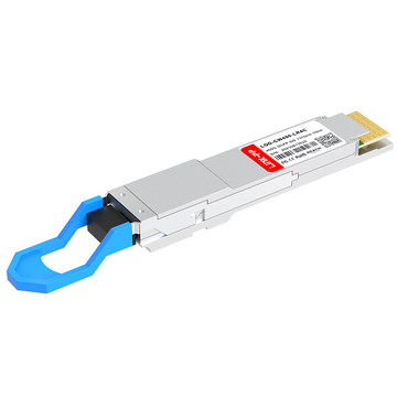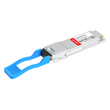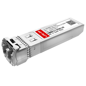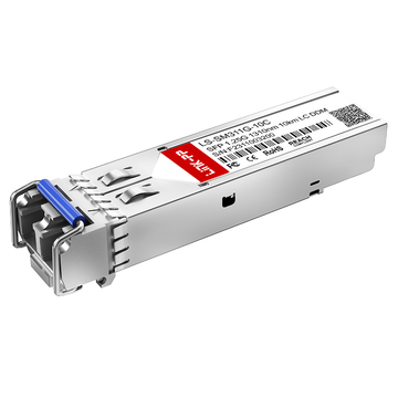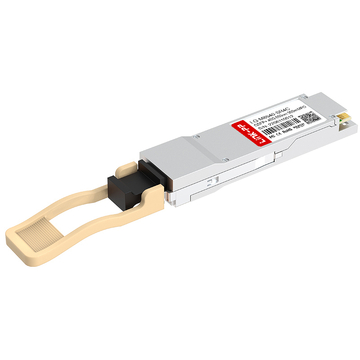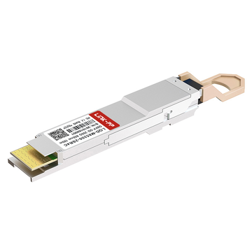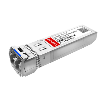
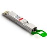
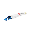
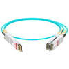






Digital Optical Monitoring (DOM) is an important feature of modern optical transceivers, allowing network engineers to monitor operating conditions such as transmitter optical power, receiver optical power, temperature, supply voltage, and laser bias current. These diagnostic measurements provide valuable insight into optical link performance and help identify potential issues before they lead to network disruptions.
However, monitoring diagnostic values alone is not enough. DOM alarm thresholds determine when a measured parameter enters a warning or alarm condition. Understanding these limits is essential for interpreting transceiver alerts, evaluating optical link health, and identifying the root causes of abnormal operating conditions.
This guide explains the key aspects of DOM alarm thresholds and how to use them in practical network monitoring:
-
What DOM alarm thresholds are and how they work.
-
The key optical transceiver parameters monitored through DOM.
-
The differences between warning thresholds and alarm thresholds.
-
How to read DOM diagnostic values and threshold tables.
-
Common causes of threshold violations and how to troubleshoot them.
With a clear understanding of DOM alarm thresholds, network engineers can interpret diagnostic alerts more accurately, investigate optical link issues efficiently, and make better-informed decisions about transceiver maintenance and network reliability.
What Are DOM Alarm Thresholds?
DOM alarm thresholds are predefined limits that help determine whether an optical transceiver is operating within its expected range. When a measured parameter exceeds a high or low threshold, the transceiver or host device may report a warning or alarm.
DOM is commonly implemented in pluggable optical transceivers such as SFP, SFP+, SFP28, QSFP+, QSFP28, QSFP-DD, and OSFP modules. Depending on the module and host platform, the monitoring function may be referred to as DOM, Digital Diagnostic Monitoring (DDM), Digital Diagnostic Functions (DDF) or Digital Diagnostic Monitoring Interface (DDMI).
Definition of DOM Alarm Thresholds
DOM alarm thresholds are reference values used to evaluate live transceiver diagnostic measurements.
These thresholds help determine whether an operating parameter is within its expected range or has reached a condition requiring attention.
For example:
-
A low Rx power warning may indicate that the received optical signal is approaching the receiver's lower operating limit.
-
A high temperature alarm may indicate that the transceiver is operating beyond its specified temperature range.
-
A high laser bias current warning may indicate a change in transmitter operating conditions.
DOM threshold values are typically stored in the transceiver's internal memory and can be accessed through the host device or diagnostic software.
The threshold values are not necessarily the same for every optical module. They depend on the transceiver's design, specifications, and operating requirements.
How DOM Thresholds Work in Optical Transceivers
DOM thresholds work by comparing measured diagnostic values against predefined high and low limits.
The monitoring process generally involves the following steps:
-
Sensors inside the transceiver measure operating parameters such as temperature, voltage, and optical power.
-
The transceiver provides diagnostic measurements through its management interface.
-
The host device or monitoring software compares the measurements with the available threshold values.
-
When a measurement crosses a threshold, the system may report a warning or alarm.
The diagnostic information is commonly accessed through the I2C interface and the transceiver's management memory, depending on the module form factor and implementation.
Many optical transceivers support digital diagnostics in accordance with industry specifications such as SFF-8472. However, the exact implementation and available monitoring features depend on the module and host platform.
Why DOM Alarm Thresholds Matter in Network Monitoring
DOM alarm thresholds help network engineers identify abnormal optical and electrical operating conditions before they cause more serious problems.
Their practical value includes:
-
Early fault detection: Identify deteriorating optical power, increasing temperature, or abnormal electrical conditions.
-
Faster troubleshooting: Narrow down potential causes of optical link instability.
-
Proactive maintenance: Detect changes in transceiver operating conditions before a complete link failure.
-
Improved network visibility: Monitor optical module health across switches, routers, and other network devices.
DOM monitoring is especially useful in data centers, enterprise networks, telecommunications infrastructure, and high-density optical deployments where multiple transceivers operate simultaneously.
Key DOM Parameters and Their Alarm Thresholds
DOM monitoring commonly includes five key parameters: Tx power, Rx power, temperature, supply voltage, and laser bias current. Each parameter provides a different indication of optical transceiver operating conditions.
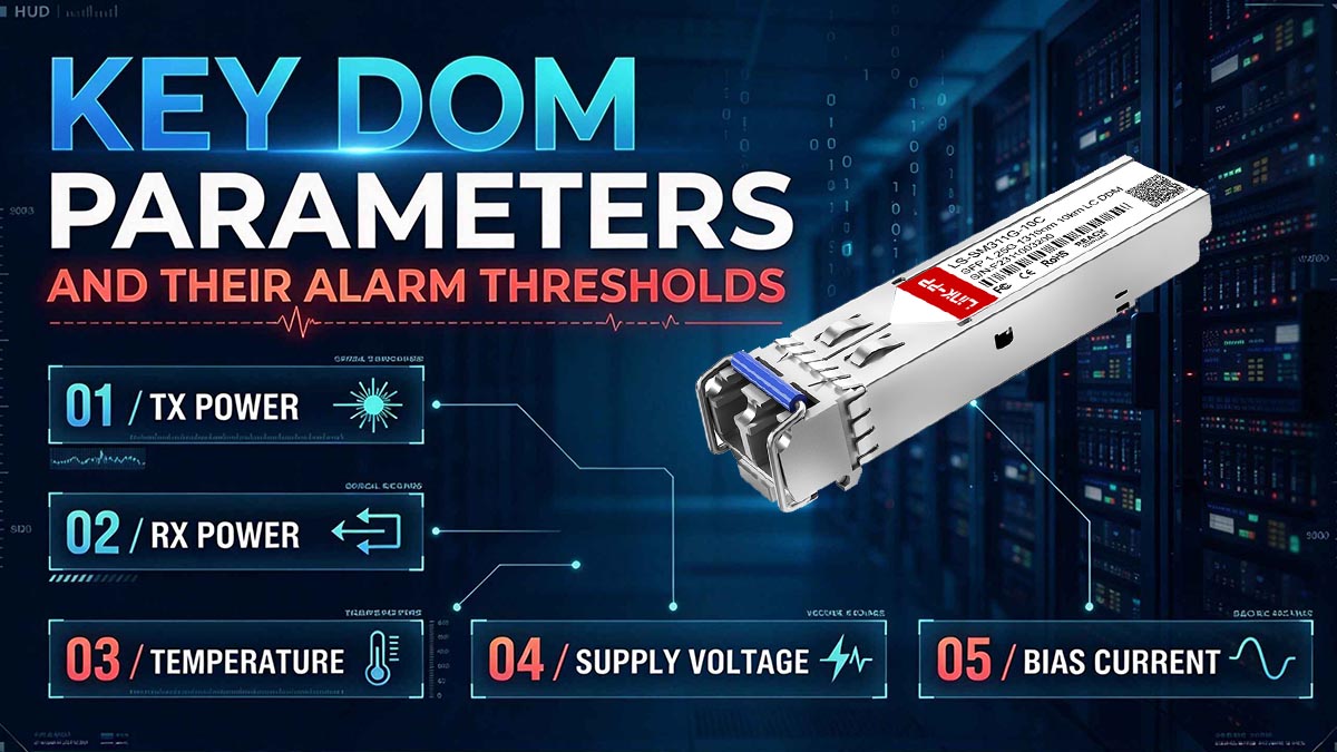
The following table summarizes the main diagnostic parameters and the conditions their thresholds can identify.
|
DOM Parameter |
Unit |
What It Measures |
Typical Threshold Concern |
|---|---|---|---|
|
Tx Power |
dBm |
Optical power transmitted by the module |
Low or high optical output |
|
Rx Power |
dBm |
Optical power received by the module |
Insufficient or excessive received signal |
|
Temperature |
°C |
Transceiver operating temperature |
Overheating or abnormal low temperature |
|
Supply Voltage |
V |
Electrical supply voltage |
Voltage outside the specified range |
|
Laser Bias Current |
mA |
Current supplied to the transmitter laser |
Abnormal laser operating current |
The threshold limits for these parameters vary by optical transceiver. Engineers should use the module datasheet and actual DOM diagnostic output to determine whether a measurement is within the expected operating range.
Transmitter Optical Power (Tx Power)
Transmitter optical power measures the optical signal strength emitted by the transceiver.
Tx power is usually reported in dBm and helps determine whether the transmitter is delivering optical output within its specified range.
A low Tx power warning or alarm may indicate:
-
Transmitter degradation.
-
Laser operating problems.
-
Abnormal laser bias current.
-
An optical module fault.
A high Tx power warning or alarm may indicate that the transmitter output exceeds its expected range, which can be relevant when connecting to a receiver with limited input power tolerance.
Tx power should be evaluated alongside the receiver's optical power and the link's optical budget rather than in isolation.
Receiver Optical Power (Rx Power)
Receiver optical power measures the strength of the optical signal reaching the transceiver's receiver.
Rx power is one of the most useful DOM parameters for evaluating the condition of an optical link.
Low Rx power may be caused by:
-
Excessive fiber attenuation.
-
Dirty or damaged connectors.
-
Incorrect fiber connections.
-
Excessive link distance.
-
A weak transmitter.
-
Fiber bends or other optical path problems.
High Rx power may occur when a strong transmitter is connected over a very short fiber link or when optical attenuation is insufficient.
When Rx power crosses a threshold, engineers should check the receiver's sensitivity and overload specifications to determine whether the signal level is acceptable.
Transceiver Temperature
Transceiver temperature indicates the module's internal operating temperature.
Temperature thresholds help identify thermal conditions that may affect transceiver operation or reliability.
Common causes of high temperature include:
-
High ambient temperature.
-
Insufficient airflow.
-
Blocked ventilation.
-
High-density module installation.
-
Excessive heat from neighboring components.
A temperature warning indicates that the module is approaching a specified limit. A temperature alarm indicates that the reported value has crossed a more critical threshold.
The actual temperature limits depend on the module's operating specifications and temperature grade.
Supply Voltage and Laser Bias Current
Supply voltage and laser bias current provide information about the electrical operating conditions of an optical transceiver.
Supply voltage monitoring helps identify whether the module is receiving an appropriate electrical supply.
Laser bias current measures the current used to operate the transmitter laser. Changes in bias current can provide useful information about transmitter behavior.
For example:
-
A supply voltage warning may indicate an electrical supply issue.
-
An abnormal bias current may indicate changing laser operating conditions.
-
Increasing bias current accompanied by declining Tx power may suggest transmitter degradation.
These parameters are most useful when interpreted together with optical power and temperature measurements.
DOM Warning Thresholds vs. Alarm Thresholds
DOM warning thresholds and alarm thresholds indicate different levels of abnormal operating conditions. Warning thresholds generally identify values approaching a limit, while alarm thresholds identify values that have crossed a more critical boundary.
The exact behavior depends on the transceiver's threshold definitions and the host device's alarm-reporting implementation.
High and Low Warning Thresholds
Warning thresholds indicate that a diagnostic parameter is approaching an abnormal operating range.
They are useful for identifying potential issues before the parameter reaches a critical limit.
A high warning occurs when a measurement exceeds its high warning threshold. A low warning occurs when a measurement falls below its low warning threshold.
Examples include:
-
Temperature approaching the module's maximum operating limit.
-
Rx power approaching the receiver's lower sensitivity boundary.
-
Laser bias current approaching its specified upper range.
Warning alerts allow engineers to investigate operating conditions while the optical link may still be functioning normally.
High and Low Alarm Thresholds
Alarm thresholds indicate that a diagnostic measurement has crossed a more critical limit.
A high alarm occurs when a measurement exceeds its high alarm threshold. A low alarm occurs when a measurement falls below its low alarm threshold.
For example:
-
A high temperature alarm may indicate that the transceiver has exceeded its specified temperature limit.
-
A low Rx power alarm may indicate that the received optical signal is below the module's expected operating range.
-
A low supply voltage alarm may indicate an electrical condition outside the specified range.
An alarm does not automatically mean that the optical link has failed. The link may remain operational even when a DOM parameter has crossed an alarm threshold.
However, the alert should be investigated because it may indicate an operating condition that could affect link stability or module reliability.
Understanding the Four Threshold Types
The four common DOM threshold categories are High Alarm (HA), Low Alarm (LA), High Warning (HW), and Low Warning (LW).
These thresholds define the upper and lower boundaries used to evaluate a diagnostic measurement.
|
Threshold Type |
Meaning |
General Interpretation |
|---|---|---|
|
High Alarm (HA) |
Upper critical limit |
Measurement exceeds the high alarm boundary |
|
Low Alarm (LA) |
Lower critical limit |
Measurement falls below the low alarm boundary |
|
High Warning (HW) |
Upper warning limit |
Measurement exceeds the high warning boundary |
|
Low Warning (LW) |
Lower warning limit |
Measurement falls below the low warning boundary |
For a typical parameter with separate warning and alarm limits, the warning boundaries are positioned within the normal operating range and the alarm boundaries define more critical conditions.
The exact relationship between warning and alarm thresholds depends on the parameter and module specification. Engineers should not assume that every DOM parameter uses identical threshold logic.
How to Read a DOM Alarm Threshold Table
A DOM alarm threshold table provides the reference values needed to interpret live diagnostic measurements. Reading the table correctly requires understanding the parameter units, threshold types, and relationship between current measurements and their limits.
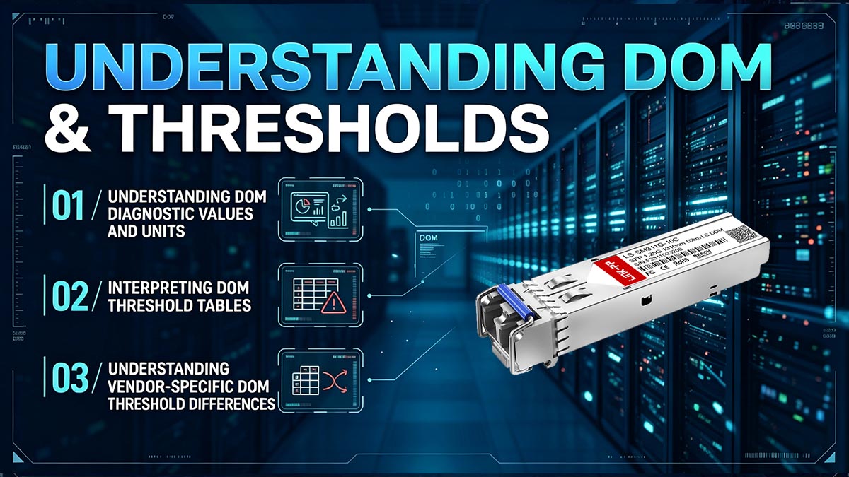
Understanding DOM Diagnostic Values and Units
DOM measurements use different units depending on the parameter being monitored.
The most common units are:
-
Optical power: dBm.
-
Temperature: °C.
-
Supply voltage: V.
-
Laser bias current: mA.
A diagnostic display typically provides the current measurement and may also show the module's threshold values.
For example, an optical transceiver might report:
-
Current Rx power: -8.5dBm.
-
Low warning threshold: -10.0dBm.
-
Low alarm threshold: -12.0dBm.
In this illustrative example, the current Rx power is above both lower limits, so neither the low warning nor the low alarm threshold has been crossed.
The values are illustrative only. Actual threshold limits depend on the transceiver model.
Interpreting DOM Threshold Tables
The most reliable way to interpret a DOM threshold table is to compare the current measurement with all four threshold limits for the same parameter.
The following example shows illustrative values for a transceiver's diagnostic parameters.
|
Parameter |
Current Value |
High Warning |
High Alarm |
Low Warning |
Low Alarm |
|---|---|---|---|---|---|
|
Tx Power |
-2.0dBm |
0.0dBm |
1.0dBm |
-5.0dBm |
-6.0dBm |
|
Rx Power |
-8.5dBm |
-1.0dBm |
0.0dBm |
-10.0dBm |
-12.0dBm |
|
Temperature |
45°C |
75°C |
85°C |
-5°C |
-10°C |
|
Supply Voltage |
3.30V |
3.50V |
3.60V |
3.10V |
3.00V |
|
Bias Current |
35mA |
70mA |
80mA |
10mA |
5mA |
These values are examples for explaining threshold interpretation. They are not universal DOM alarm limits.
To interpret a threshold table correctly:
-
Identify the parameter being monitored.
-
Confirm the unit of measurement.
-
Find the current diagnostic value.
-
Compare it with the high and low warning and alarm thresholds.
-
Determine whether the measurement is normal, approaching a limit, or beyond a threshold.
For optical power, remember that dBm uses a logarithmic scale. A more negative value represents lower optical power, while a less negative value represents higher optical power.
Understanding Vendor-Specific DOM Threshold Differences
DOM thresholds are not identical across all optical transceivers.
Differences may result from:
-
Transceiver form factor.
-
Optical wavelength.
-
Transmission distance.
-
Laser type.
-
Receiver design.
-
Temperature grade.
-
Manufacturer specifications.
For example, a 10GBASE-SR transceiver and a 10GBASE-LR transceiver may have different optical power specifications and diagnostic threshold values.
Similarly, an industrial-temperature optical module may have different temperature limits from a commercial-temperature module.
Engineers should always consult the specific module datasheet and diagnostic output rather than applying a generic threshold table to every transceiver.
Common Causes of DOM Alarm Threshold Violations
DOM alarm threshold violations can result from optical link problems, electrical conditions, environmental factors, or transceiver degradation. Identifying the affected parameter is the first step toward determining the likely cause.
Optical Power Threshold Violations
Optical power threshold violations commonly indicate a change in the optical signal level between the transmitter and receiver.
Low Rx power is one of the most common DOM alerts in optical networking. It may occur even when the link remains active.
Common causes of low Rx power include:
-
Dirty fiber connectors or transceiver interfaces.
-
Excessive insertion loss along the optical path.
-
Fiber damage or excessive bending.
-
Incorrect fiber type or connection.
-
Link distance exceeding the module's supported reach.
-
A transmitter operating below its expected optical output.
High Rx power can occur when a short fiber connection delivers a signal that exceeds the receiver's specified input range.
When an optical power threshold is violated, engineers should evaluate both ends of the link. The transmitter's Tx power, receiver's Rx power, fiber loss, and module specifications provide a more complete picture than a single diagnostic measurement.
Temperature and Voltage Threshold Violations
Temperature and voltage threshold violations usually indicate environmental or electrical operating conditions that require investigation.
High temperature alerts may be caused by:
-
Poor airflow around network equipment.
-
High ambient temperature.
-
Insufficient cooling.
-
High module density in a switch or router.
-
Heat generated by adjacent components.
Voltage alerts may indicate:
-
An unstable electrical supply.
-
A host device power issue.
-
An abnormal module operating condition.
-
A transceiver fault.
These alerts should be interpreted according to the module's specifications and the host device's diagnostic reporting.
A temperature warning does not necessarily mean the module has failed. However, repeated high-temperature alerts may indicate an environmental condition that needs correction.
Laser Bias Current and Transmitter Degradation
Laser bias current threshold violations can provide insight into the operating condition of the optical transmitter.
An increase in laser bias current may occur as the transmitter's operating characteristics change. In some cases, increasing bias current combined with declining Tx power may indicate laser degradation.
Other possible causes include:
-
Abnormal transmitter operating conditions.
-
Electrical supply instability.
-
Transceiver component issues.
-
Temperature-related changes in laser behavior.
Bias current alone is not sufficient to confirm transmitter degradation. Engineers should compare bias current with Tx power, temperature, and other available diagnostic measurements.
A consistent trend across multiple measurements is more useful than a single isolated alert.
How to Troubleshoot DOM Alarm Threshold Alerts
Troubleshooting DOM alarm threshold alerts involves identifying the affected parameter, checking the optical and electrical conditions, verifying module specifications, and determining whether corrective action is required.
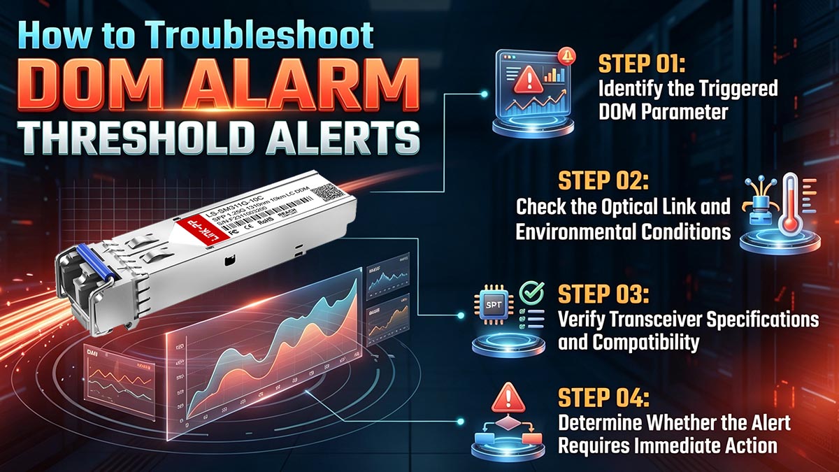
The following steps provide a practical process for investigating DOM warnings and alarms.
Step 1: Identify the Triggered DOM Parameter
Start by checking the host device's transceiver diagnostic output.
Depending on the platform, engineers may use commands such as:
-
show interfaces transceiver -
show interfaces transceiver detail -
show interface diagnostics optics -
show transceiver
The exact command syntax varies by switch, router, and operating system.
Record the following information:
-
Transceiver model and part number.
-
Affected interface.
-
Triggered DOM parameter.
-
Current diagnostic measurement.
-
Threshold value that was crossed.
-
Warning or alarm status.
For example, a low Rx power warning should be investigated differently from a high temperature alarm.
Identifying the specific parameter first prevents unnecessary module replacement or unrelated troubleshooting.
Step 2: Check the Optical Link and Environmental Conditions
After identifying the affected parameter, check the physical and environmental conditions that may contribute to the alert.
For optical power alerts:
-
Inspect the fiber connections.
-
Clean connectors using appropriate fiber cleaning procedures.
-
Verify that the correct fiber type is used.
-
Check the optical path for damage or excessive bending.
-
Confirm that the link distance is within the transceiver's supported reach.
For temperature alerts:
-
Check the ambient temperature.
-
Verify that cooling and airflow are adequate.
-
Inspect the equipment installation for ventilation problems.
For voltage alerts:
-
Review the host device's electrical condition.
-
Check whether other modules report similar voltage issues.
-
Investigate possible power supply or host platform problems.
After correcting an identified physical or environmental issue, recheck the DOM measurements to determine whether the alert has cleared.
Step 3: Verify Transceiver Specifications and Compatibility
The next step is to confirm that the module's specifications are consistent with the measured operating conditions.
Review the transceiver datasheet for:
-
Supported data rate.
-
Optical wavelength.
-
Transmission distance.
-
Tx power range.
-
Rx sensitivity and overload limits.
-
Operating temperature range.
-
Supply voltage specifications.
-
DOM support and diagnostic information.
For example, a receiver may report low optical power because the optical path exceeds the module's supported reach or because the selected transceiver type is unsuitable for the link.
Engineers should also confirm that the transceiver is compatible with the host device and that the host supports the module's diagnostic features.
A compatibility issue may affect how diagnostic information is reported, although it does not necessarily mean the underlying DOM measurement is incorrect.
Step 4: Determine Whether the Alert Requires Immediate Action
Not every DOM alert requires the same response.
The appropriate action depends on the parameter, threshold severity, and impact on the optical link.
Consider the following general approach:
-
Warning: Investigate the operating condition and monitor for changes.
-
Alarm: Check whether the module or link is operating outside its specified range.
-
Repeated alert: Investigate whether an underlying physical, environmental, or electrical problem remains unresolved.
-
Link failure: Perform additional troubleshooting to determine whether the DOM condition is related to the outage.
A warning or alarm should not automatically trigger transceiver replacement. The measured value, module specification, link status, and potential causes should be evaluated together.
When the alert indicates an operating condition outside the module's specified limits, corrective action may include improving airflow, repairing the optical path, correcting the electrical condition, or replacing a faulty transceiver.
Conclusion
DOM alarm thresholds provide essential information for evaluating optical transceiver operating conditions and identifying potential problems in fiber-optic networks. By comparing live diagnostic measurements with high and low warning and alarm limits, network engineers can determine whether a transceiver is operating normally, approaching an abnormal condition, or exceeding its specified range.
The key points to remember are:
-
DOM alarm thresholds help identify abnormal Tx power, Rx power, temperature, supply voltage, and laser bias current.
-
Warning thresholds indicate conditions approaching a limit, while alarm thresholds indicate more critical threshold violations.
-
Actual DOM threshold values vary by transceiver model, specifications, and operating conditions.
-
Effective troubleshooting requires checking optical power, fiber connections, environmental conditions, electrical parameters, and module compatibility.
Understanding DOM alarm thresholds is an important part of maintaining reliable optical links. Network engineers should use the module datasheet and host device diagnostic output together to interpret alerts accurately and determine the appropriate corrective action.
For engineers evaluating optical transceivers for network deployment, the LINK-PP Official Store provides an additional resource for reviewing compatible optical module options and their technical specifications. Checking module specifications before deployment helps ensure that optical characteristics, monitoring capabilities, and host compatibility align with network requirements.