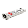






CRC/FCS errors on a fiber link can be confusing, especially when the connection is still active but network performance is getting worse. These errors often appear in switch port statistics and may indicate that some data was damaged during transmission.
A faulty optical transceiver module can cause CRC/FCS errors, but it is not always the source of the problem. Dirty fiber connectors, damaged cables, incorrect optical power levels, and faulty network ports can also affect data transmission.
So, how can you tell if the optical module is causing the errors? This article explains what CRC/FCS errors mean, how they relate to optical transceivers, and how to find the actual cause before replacing any hardware.
What Are CRC/FCS Errors in an Optical Transceiver Module Link?
CRC/FCS errors occur when a network device receives an Ethernet frame that fails its data integrity check. In simple terms, the received data does not match the expected error-checking value.
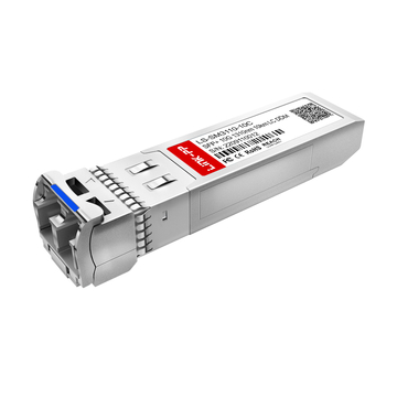
On a fiber link, these errors may appear when data passes between switches, routers, or servers through SFP, SFP+, or QSFP optical transceiver modules. However, an error does not automatically mean the transceiver is defective.

Understanding CRC and FCS in Fiber Networks
CRC (Cyclic Redundancy Check) and FCS (Frame Check Sequence) work together to detect damaged Ethernet frames. Although they are closely related, they have different functions.
| Term | Meaning | Main Function |
| CRC | Cyclic Redundancy Check | Calculates a value to detect data errors |
| FCS | Frame Check Sequence | Stores the CRC value at the end of an Ethernet frame |
For example, when a switch sends data through a fiber link, it includes an FCS value in each Ethernet frame. The receiving device uses CRC to check whether the frame arrived correctly.
If the values do not match, the device detects an error. This helps prevent damaged frames from being accepted as valid data.
How CRC/FCS Errors Are Detected
Ethernet devices automatically check received frames for errors. This process takes place in the network interface rather than inside the optical module itself.
The basic process includes four steps:
- Send Data: The sending device calculates a CRC value and adds it to the frame as an FCS.
- Transmit the Frame: The optical module converts electrical signals into optical signals for transmission over fiber.
- Check Received Data: The receiving device recalculates the CRC based on the received frame data and compares it with the value in the FCS field.
- Detect Errors: If the values do not match, the frame is marked as corrupted and is normally discarded.
A CRC/FCS error tells you that a frame failed its integrity check. It does not identify exactly where the data was damaged.
Common Signs of CRC/FCS Errors on Fiber Links
CRC/FCS errors are not always easy to notice during normal network use. Some fiber links remain active even when damaged frames are being received.
Common warning signs include:
- Increasing Error Counters: CRC or FCS error counts keep rising on a switch port.
- Packet Loss: Some data frames are discarded because they fail the integrity check.
- Slow Data Transfers: Repeated errors and retransmissions may reduce network throughput.
- Unstable Connections: Applications may experience delays or brief interruptions.
- Normal Link Status: The port may still show "Link Up" despite receiving corrupted frames.
For example, a fiber connection may remain active while its CRC error counter continues to increase. Further checks are needed to determine whether the problem comes from the optical module, fiber cable, or network equipment.
CRC/FCS errors indicate that Ethernet frames have failed their integrity checks, but they do not confirm an optical transceiver failure. The next step is to understand how problems with the module can lead to these errors.
How Can an Optical Transceiver Module Cause CRC/FCS Errors?
An optical transceiver converts electrical signals into optical signals and back again. If its transmission or reception performance becomes unstable, the receiving device may detect incorrect data bits.
These bit errors can cause Ethernet frames to fail CRC/FCS checks. The following factors explain how a faulty transceiver may affect data transmission.
Optical Signal Quality and Data Transmission Errors
A fiber connection needs a clear and stable optical signal to transfer data correctly. If the signal becomes weak or distorted, the receiver may have trouble reading some data bits.
Poor signal quality can lead to several problems:
- Bit Errors: Received bits may differ from the original data.
- Corrupted Frames: Bit errors can cause Ethernet frames to fail FCS checks.
- Packet Loss: Frames with detected errors are normally discarded.
The connection may still carry data, but repeated frame errors can reduce network reliability.
Faulty Transmitter or Receiver Components
An optical module contains a transmitter and a receiver. Problems with either component can affect how accurately data is sent or received.
| Component | Possible Problem | Effect on Data Transmission |
| Optical Transmitter | Unstable or poor-quality optical output | The remote device may receive incorrect data bits |
| Optical Receiver | Failure to detect incoming signals correctly | Received frames may contain bit errors |
For example, a faulty transmitter may send a poor-quality optical signal. The remote switch could then receive corrupted frames and report CRC errors.
These problems may occur even when the network device still recognizes the installed module.
Unstable Optical Power and Signal Loss
Optical power affects how well a receiver can detect incoming signals. Both insufficient and excessive received power can cause transmission errors.
Two important values are:
- Tx Power (Transmit Power): The amount of optical power sent by the module.
- Rx Power (Receive Power): The amount of optical power received from the fiber link.
If Rx Power falls below the supported range, the receiver may struggle to read data correctly. If it exceeds the maximum supported level, the receiver may experience overload.
Many optical modules support Digital Diagnostic Monitoring (DDM/DOM), which provides optical power readings. These values help monitor signal conditions, although they cannot directly identify every transmission problem.
CRC/FCS Errors Without a Link Failure
A fiber link can remain active even when the received signal contains occasional bit errors. This happens when the connection can still maintain its link status, but some Ethernet frames are not received correctly.
For example, a switch may show the following conditions:
| Network Status | Possible Observation |
| Link Status | Up |
| Port Speed | Operating at the negotiated speed |
| CRC/FCS Errors | Increasing |
| Data Transfer | Slower or unstable |
In this situation, the connection is still established, but data transmission may not be fully reliable.
A faulty transceiver can affect signal quality without causing a complete link failure, making frame error counters useful indicators of possible transmission problems.
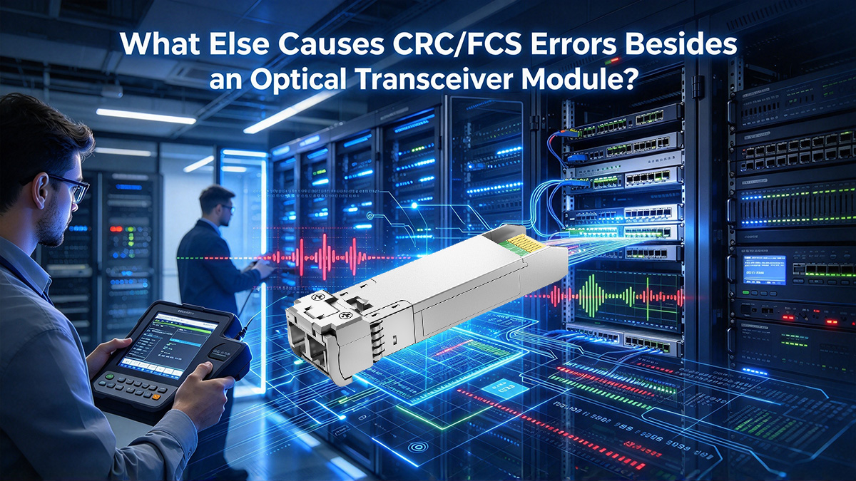
What Else Causes CRC/FCS Errors Besides an Optical Transceiver Module?
CRC/FCS errors do not always come from a faulty optical transceiver module. Even when the transceiver works normally, problems with fiber cables, connectors, optical power, or network hardware can still damage transmitted data.
Understanding these possible causes helps you avoid replacing a working module when the actual problem is somewhere else in the fiber link.
Dirty or Damaged Fiber Connectors
Fiber connectors need clean and properly aligned surfaces to carry optical signals. Dust, dirt, or physical damage can weaken the signal passing through the connection.
Common connector problems include:
- Dust or Dirt: Blocks or scatters light at the fiber connection.
- Scratched End Faces: Reduce the quality of the optical connection.
- Loose Connections: May cause unstable signal transmission.
These issues can lead to CRC/FCS errors even when the optical transceiver is working correctly.
Excessive Fiber Bending and Cable Loss
Fiber cables can lose signal strength when they are bent too sharply or physically damaged. This loss may reduce the amount of light reaching the receiver.
Several cable conditions can affect transmission:
- Sharp Bends: Increase optical signal loss along the fiber.
- Damaged Cables: May interrupt or weaken the light signal.
- Long Fiber Runs: Can cause excessive loss if the total link budget is exceeded.
For example, a fiber link may experience CRC errors if a tightly bent cable reduces the received signal strength. The optical module itself may still be working normally.
Incorrect Optical Power Levels
The optical power reaching a receiver must stay within its supported range. Too little or too much received power may lead to data errors.
| Optical Power Issue | Possible Cause | Effect on the Fiber Link |
| Low Rx Power | High fiber loss or dirty connectors | Weak received signal |
| High Rx Power | Excessive received optical power | Possible receiver overload |
| Fluctuating Rx Power | Unstable fiber connections | Intermittent transmission errors |
For example, a short fiber connection using a long-reach optical module may deliver too much power to the receiver if the link has insufficient attenuation.
Optical power problems should be checked against the module's specifications before assuming the transceiver is defective.
Network Port and Hardware Issues
Not all CRC/FCS errors begin in the optical path. Network equipment can also contain faulty components that affect Ethernet frame processing.
Possible hardware issues include:
- Switch or Router Ports: Damaged interfaces may cause reception or transmission errors.
- Network Interface Cards (NICs): A faulty server network card may produce corrupted frames.
- Line Cards or Internal Hardware: Problems with device circuits may affect data handling.
In some cases, network configuration issues may also contribute to CRC/FCS errors. For example, certain MTU mismatches can cause frames to be incorrectly truncated on specific devices.
If the fiber cable and transceiver are working normally, the connected network equipment may need further inspection.
CRC/FCS errors can come from several parts of a fiber connection, so checking the complete link is important before deciding that the optical module is faulty.
How to Identify a Faulty Optical Transceiver Module
Identifying a faulty optical module requires checking more than its link status. Error counters, optical power readings, and monitoring alerts can provide useful clues about possible module problems.
The following checks can help you decide whether the transceiver needs further testing.
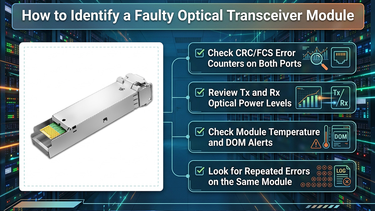
Check CRC/FCS Error Counters on Both Ports
CRC/FCS error counters help show where corrupted Ethernet frames are being received. Comparing both ends of the fiber link can help narrow down the affected transmission direction.
Focus on these details:
- Error Count: Check how many CRC/FCS errors have been recorded.
- Error Growth: See whether new errors continue to appear.
- Port Comparison: Identify which side is reporting receive errors.
For example, if one switch port shows increasing CRC errors while the other reports no new errors, the problem may affect one direction of the fiber link.
However, error counters cannot identify the faulty component on their own.
Review Tx and Rx Optical Power Levels
Optical power readings can help identify whether the transmitter or receiver is operating outside its expected range.
Compare the measured values with the limits in the module's specifications.
| Reading | What to Look For | Possible Indication |
| Tx Power | Outside the specified range | Possible local transmitter issue |
| Rx Power | Below the minimum limit | Weak incoming optical signal |
| Rx Power | Above the maximum limit | Possible receiver overload |
| Power Fluctuation | Unstable readings over time | Possible intermittent link issue |
Abnormal Tx Power may point to a problem with the local transmitter. Abnormal Rx Power may be caused by the remote transmitter, fiber loss, or the local receiver.
Checking both ends of the connection helps narrow down the possible cause.
Check Module Temperature and DOM Alerts
Digital Diagnostic Monitoring (DDM/DOM) can provide additional information about a transceiver's operating condition.
Important values to review include:
- Temperature: Check whether the module is operating within its supported range.
- Laser Bias Current: Look for abnormal readings or repeated warnings.
- Supply Voltage: Check whether the module receives the expected power supply.
- Warning and Alarm Flags: Look for values that exceed the defined thresholds.
For example, repeated temperature alarms together with increasing CRC/FCS errors may indicate a module that needs closer inspection.
However, normal monitoring readings do not guarantee that the module is working without transmission errors.
Look for Repeated Errors on the Same Module
Error patterns can provide stronger evidence when a particular transceiver is suspected.
Look for the following situations:
- Repeated Errors: CRC/FCS errors continue to appear when the suspected module is in use.
- Errors Follow the Module: Similar errors appear when the module is tested in another known-good compatible port.
- Consistent Conditions: Errors return under similar traffic or operating conditions.
If CRC/FCS errors follow the same transceiver across different known-good connections, the module is more likely to be responsible.
This pattern provides useful evidence, but controlled testing is still needed to confirm the fault.
Combining interface statistics, DOM readings, and repeated error patterns can help determine whether the optical module is a likely source of the problem.
How to Troubleshoot Optical Transceiver Module CRC/FCS Errors
When CRC/FCS errors appear on a fiber link, replacing the optical transceiver module immediately may not solve the problem. A better approach is to check the connection step by step and rule out other possible causes first.
Follow these steps to find the source of the errors and avoid unnecessary module replacement.
Inspect and Clean Fiber Connections
Start by checking the fiber connectors at both ends of the link. Dust, dirt, or loose connections can weaken optical signals and cause transmission errors.
Follow these basic steps:
- Disconnect the fiber cable carefully during a suitable maintenance window.
- Inspect the connector end faces using proper fiber inspection equipment.
- Clean dirty connectors with approved fiber cleaning tools.
- Reconnect the fiber securely and check the link status.
Never look directly into a fiber connector, as invisible laser light may be present.
If CRC/FCS errors stop increasing after cleaning, the problem may have been caused by poor fiber connections rather than a faulty module.
Verify Module and Device Compatibility
Next, confirm that the optical module matches the connected network equipment and fiber link. Incompatible specifications can cause connection failures or unstable transmission.
Check the following items:
- Device Compatibility: Confirm that the switch or router supports the installed module.
- Data Rate: Make sure both ends support the required connection speed.
- Wavelength: Verify that the optical wavelengths match the link requirements.
- Fiber Type: Check whether the module supports the installed single-mode or multimode fiber.
- FEC Settings: Confirm that both ends use compatible Forward Error Correction settings where required.
Also, check that the module's optical power specifications are suitable for the actual link distance and loss.
If the settings are correct but CRC/FCS errors continue, move on to checking the fiber path and network ports.
Check Fiber Cables and Network Ports
If the connectors and module specifications appear correct, check the other components along the fiber link.
You can perform these checks:
- Replace the Fiber Patch Cable: Use a known-good cable to rule out cable damage or excessive loss.
- Inspect the Fiber Path: Check patch panels and intermediate connections for possible signal loss.
- Check Device Logs: Look for port errors, hardware warnings, or unexpected link events.
- Test Another Network Port: If practical, use a compatible port to help identify interface problems.
Change one component at a time and monitor the connection after each test. This makes it easier to find the source of the errors.
If the fiber path and network ports appear normal, the optical module becomes a stronger suspect.
Replace the Module With a Known-Good Unit
If the previous checks do not identify the problem, try replacing the suspected transceiver with a known-good compatible module.
Follow these steps:
- Record the current CRC/FCS error counts.
- Disconnect the fiber and safely remove the suspected module.
- Insert a known-good module with matching specifications.
- Reconnect the fiber and confirm that the link is active.
- Monitor the connection for new CRC/FCS errors.
If the errors stop after replacement, the original module may have been faulty.
However, test the replacement under similar network conditions before drawing a final conclusion.
Compare Error Counters After Replacement
After replacing the module, compare the CRC/FCS error counters before and after the test.
The results can help you understand whether the replacement solved the problem.
| Test Result | Possible Meaning |
| Errors stop increasing | Original module may have been faulty |
| Errors continue increasing | Another part of the link may still have a problem |
| Errors decrease but remain | The issue may not be fully resolved |
| Errors appear intermittently | An unstable connection or hardware issue may remain |
Some network devices keep previous error counts until the counters are cleared or reset. Focus on newly recorded errors rather than historical totals.
For a fair comparison, monitor the link over similar time periods and traffic conditions.
By checking the fiber path, network equipment, and transceiver separately, you can identify the likely cause of CRC/FCS errors before deciding whether a module needs replacement.
How to Choose an Optical Transceiver Module to Reduce CRC/FCS Errors
Choosing the right optical transceiver module can help reduce the risk of transmission errors caused by incompatible or unsuitable hardware. A reliable fiber connection depends on more than just the module's data rate or price.
Before buying a replacement transceiver, check its specifications, optical power requirements, device compatibility, and testing quality.
Match Module Specifications to the Fiber Link
An optical transceiver must match the requirements of the connected network and fiber cable. Choosing the wrong module may lead to link failures or unstable data transmission.
Check these basic specifications:
- Form Factor: Select the correct module type, such as SFP, SFP+, SFP28, QSFP+, QSFP28 or QSFP-DD.
- Data Rate: Match the module speed to the network port and application.
- Wavelength: Confirm that both ends use compatible optical wavelengths.
- Fiber Type: Choose a module designed for single-mode or multimode fiber.
- Connector Type: Make sure the optical interface matches the installed fiber connections.
Matching these specifications helps avoid connection issues that may contribute to CRC/FCS errors.
Check Optical Power Budget and Link Distance
Every optical module has a supported transmission range and optical power limits. The fiber link must provide enough received power without exceeding the receiver's maximum input level.
Before purchasing, consider the following:
| Factor | What to Check |
| Link Distance | Actual fiber length between devices |
| Tx Power | Supported optical output range |
| Receiver Sensitivity | Minimum received power needed for reliable operation |
| Receiver Overload | Maximum safe received power |
| Fiber Loss | Loss from cables, connectors, and other optical components |
Do not choose a transceiver based only on its advertised maximum distance. A suitable optical power budget helps keep the received signal within the supported range.
Verify Compatibility With Network Equipment
Not every optical transceiver module works with every switch, router, or network card. Some devices require specific transceiver coding or supported module models.
Before placing an order, check:
- Switch or Router Model: Confirm that the transceiver supports your device.
- Module Recognition: Make sure the equipment can detect the module correctly.
- Port Requirements: Check supported speeds and any required FEC settings.
- Monitoring Support: Confirm that DDM/DOM information can be read when needed.
For third-party compatible optical modules, reviewing compatibility information or requesting a test report can help reduce deployment problems.
Choose Modules With Reliable Quality Testing
Quality testing helps identify optical signal and data transmission problems before an optical transceiver module is installed. When comparing suppliers, look for testing that covers optical output, signal quality, bit error rate (BER), and operating temperature.
LINK-PP offers a wide range of transceiver modules from 1G to 1.6T for different network applications. Its testing resources include optical spectrum, eye pattern, BER, and compatibility checks to help buyers evaluate module quality and device support.
You can explore LINK-PP optical transceivers or use the Compatibility Tool to find suitable modules for your network equipment. If you are unsure which module to order, request compatibility information before purchasing.
A properly selected and tested optical transceiver can help reduce hardware-related transmission problems, although fiber quality and network conditions remain equally important.
FAQs About Optical Transceiver Module CRC/FCS Errors
CRC/FCS errors can raise questions about fiber link reliability and whether an optical transceiver module needs replacement. Here are answers to some common questions that can help you better understand these errors and make the right decision.
Can CRC/FCS Errors Occur With Normal Optical Power?
Yes, CRC/FCS errors can still occur when Tx and Rx power readings are within the normal range. Signal quality problems, faulty network hardware, or damaged data from upstream devices may also cause these errors.
Can a Fiber Link Stay Up With CRC/FCS Errors?
Yes, a fiber link may remain active even when some Ethernet frames are corrupted. The switch may still show "Link Up" while CRC/FCS error counters continue to increase.
Does Replacing the Optical Module Always Fix CRC Errors?
No, replacing the optical module only helps if the original module was causing the problem. If the errors come from fiber cables, connectors, or network ports, they may continue after replacement.
When Should You Replace an Optical Transceiver Module?
Consider replacing the module if CRC/FCS errors continue after other link problems have been ruled out. Testing with a known-good compatible module can help confirm whether the original transceiver is faulty.
Conclusion: Is the Optical Transceiver Module Causing CRC/FCS Errors?
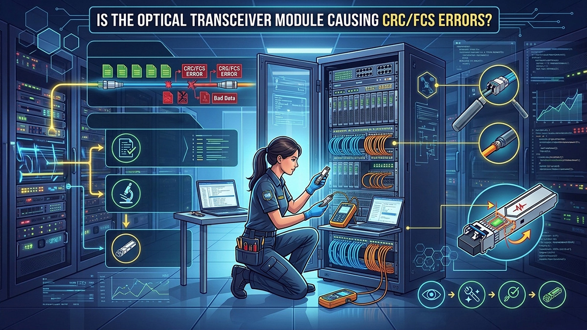
CRC/FCS errors on a fiber link may be caused by a faulty optical transceiver module, but other network components can also be responsible. Finding the actual cause requires checking the complete fiber connection.
Here are three important things to remember:
- Check the Fiber Link First: Dirty connectors, damaged cables, and optical power issues can cause CRC/FCS errors even when the module works normally.
- Look for Signs of Module Failure: Review error counters and DOM readings to identify possible problems with the transceiver.
- Test Before Replacing: Use a known-good compatible module to check whether the errors are related to the original transceiver.
Choosing a compatible and properly tested optical module can help reduce transmission problems and support reliable network connections.
If you need a replacement or plan to upgrade your fiber network, visit the LINK-PP Official Store to explore optical transceiver modules and submit a quote request to find a suitable solution for your network requirements.