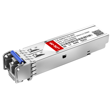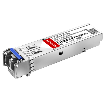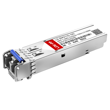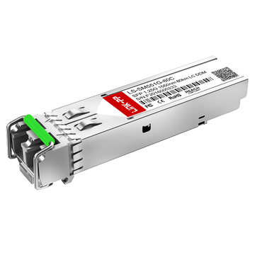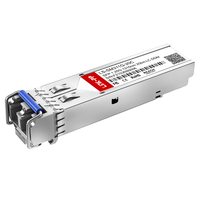
Cisco single mode fiber SFP modules are widely used in 1G optical networks to enable stable, long-distance data transmission over single mode fiber. Among them, 1310nm and 1550nm wavelengths are the most common options, each offering different performance characteristics in terms of attenuation, dispersion, and achievable transmission distance. Understanding how these transceiver modules work and how they differ is essential for designing efficient and reliable fiber links.
When deploying Cisco single mode fiber SFP solutions, link budget planning becomes a critical factor. It determines whether the optical signal can travel the required distance without degradation or failure. By analyzing key parameters such as transmit power, receiver sensitivity, fiber loss, and connector loss, network engineers can accurately evaluate link performance and choose the right fiber optic SFP module for specific scenarios.
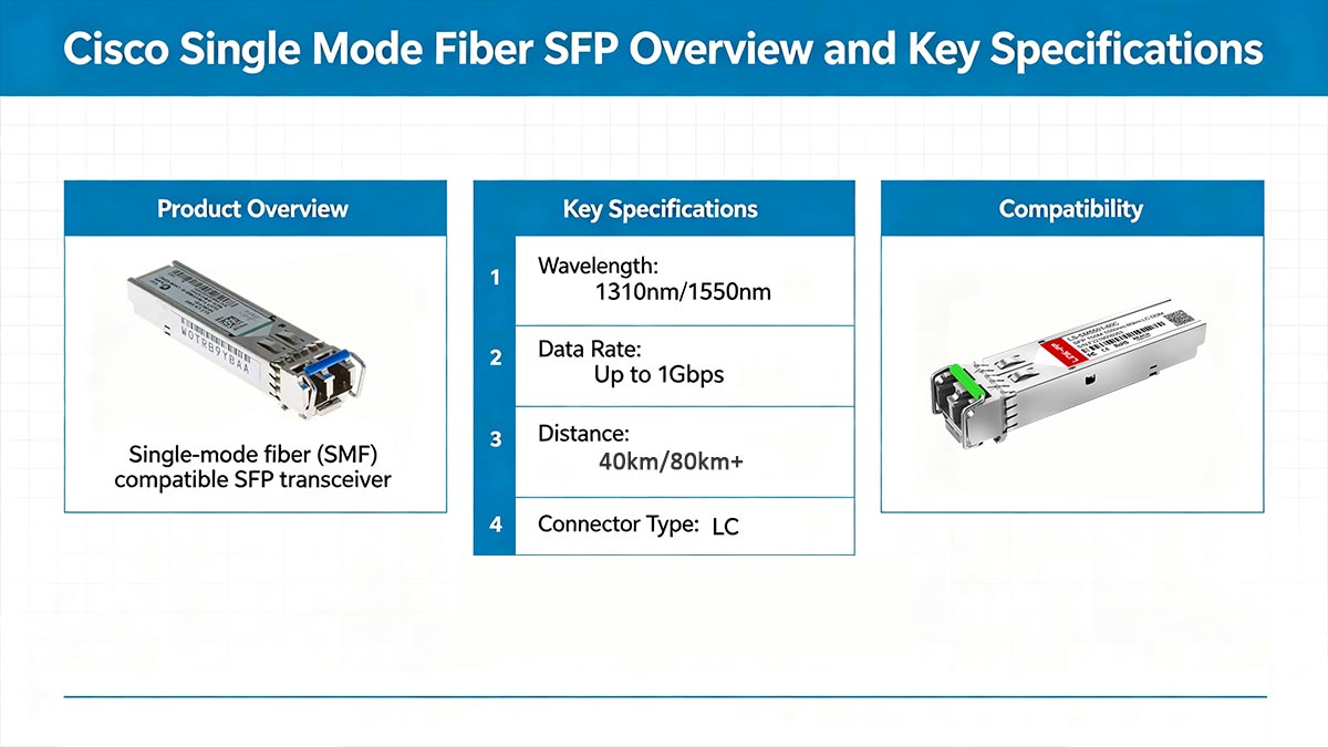
❇️ Cisco Single Mode Fiber SFP Overview and Key Specifications
The Cisco single mode fiber SFP series provides compact, hot-swappable optical transceivers for high-performance 1G Ethernet and fiber channel applications. These modules are designed to deliver stable, long-distance connectivity over single mode fiber, supporting wavelengths of 1310nm and 1550nm for optimal transmission efficiency. Their flexibility and reliability make them essential in enterprise backbones, data centers, and telecom networks.
What Is a Single Mode Fiber SFP Module
A single mode fiber SFP is a miniaturized transceiver module used to convert electrical signals from network devices into optical signals transmitted through single mode fiber cables. Unlike multimode SFP modules, the single mode SFP offers low signal attenuation and can support distances from 10km up to 80km or more, depending on its optical design and wavelength. They typically operate with LC duplex connectors, ensuring compatibility with standard fiber infrastructures.
Core Specifications of Cisco Single Mode Fiber SFP 1G
The core specifications of Cisco single mode fiber 1G SFP modules define their performance capabilities and compatibility with network infrastructure. Key parameters include operating wavelength, transmission distance, transmit power, receiver sensitivity, and interface standards.
For example, most Cisco 1G SFP modules comply with IEEE 1000BASE-LX or 1000BASE-ZX standards, using LC connectors and supporting Digital Optical Monitoring (DOM) for real-time performance tracking. These specifications ensure interoperability and predictable link behavior in various deployment scenarios.
Differences Between 1310nm and 1550nm Optics Transceivers
The primary difference between 1310nm and 1550nm Cisco single mode transceivers lies in their transmission characteristics and distance capabilities. The 1310nm wavelength is typically used for medium-range applications (e.g., 10km to 20km), offering lower dispersion and stable performance. In contrast, 1550nm modules are optimized for long-distance transmission (40km, 80km or more) due to lower attenuation in fiber.
To better understand their differences, the following table compares key parameters:
| Parameter | 1310nm SFP | 1550nm SFP |
| Typical Transmission Range | 10km / 20km | 40km / 80km+ |
| Fiber Attenuation | ~0.35dB/km | ~0.20dB/km |
| Chromatic Dispersion | Lower | Higher (but manageable) |
| Optical Power Budget | Moderate | Higher link budget for greater reach |
| Cost | Generally lower | Generally higher |
| Common Standard | 1000BASE-LX | 1000BASE-ZX |
❇️ Cisco Single Mode Fiber SFP Wavelength Standards
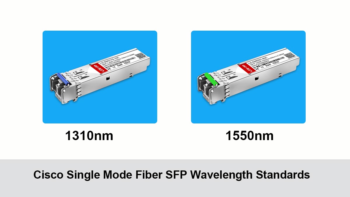
The Cisco single mode fiber SFP wavelength standards define how optical signals are transmitted and maintained over varying distances. The two key wavelengths — 1310nm and 1550nm — are standardized across the fiber optics industry for 1G data transmission, each offering unique characteristics in terms of dispersion, attenuation, and reach. Understanding these wavelength behaviors helps network designers ensure optimal performance across different fiber deployments.
Characteristics of 1310nm Transmission
The 1310nm wavelength operates in the O-band (Original band), which is commonly used for medium-range fiber transmissions. It is characterized by low dispersion and moderate attenuation, making it suitable for metropolitan and enterprise networks where link distances typically range between 10km and 20km.
Because light at this wavelength maintains stability through minimal chromatic distortion, it’s ideal for applications requiring consistent signal integrity without the need for dispersion compensating modules. In practical use, 1310nm optics also offer simpler optical design and lower cost, making them an efficient choice for most local connections where extended reach is not required.
Characteristics of 1550nm Transmission
Operating in the C-band (Conventional band), the 1550nm wavelength is favored for long-haul and backbone optical transmission. It exhibits lower fiber attenuation, commonly around 0.20dB/km, meaning less signal loss per unit distance. This allows 1550nm optics to achieve extended ranges from 40km to 80km or more, depending on system power and fiber quality.
However, the longer wavelength also introduces higher chromatic dispersion, which may require dispersion compensation for stable performance on very long links. Cisco single mode fiber SFP designs its 1550nm transceivers to handle these effects efficiently, enabling reliable connectivity for inter-campus or carrier-grade network segments.
Attenuation and Dispersion Differences
In fiber optics, attenuation describes how signal strength decreases along the fiber, whereas dispersion relates to how light pulses spread over time. The 1310nm wavelength experiences slightly higher attenuation but lower dispersion, while 1550nm offers minimal attenuation with higher dispersion risk over long distances.
For reference:
- Typical fiber attenuation: ~0.35dB/km at 1310nm and ~0.20dB/km at 1550nm.
- Typical chromatic dispersion: ~1ps/nm·km at 1310nm and ~18ps/nm·km at 1550nm.
These physical properties guide engineers in balancing signal clarity against distance capability when selecting optical modules for deployment.
Choosing the Right Wavelength for Distance
Selecting the appropriate wavelength depends on multiple factors, including transmission distance, network architecture, and cost considerations. For short to medium distances, 1310nm provides a simple and cost-effective solution with stable performance.
For longer distances or applications requiring minimal signal loss, 1550nm is generally preferred due to its superior attenuation characteristics and support for amplification. In practice, network designers must evaluate link requirements, power budgets, and future scalability to determine the most suitable wavelength for Cisco single mode fiber SFP deployments.
❇️ Cisco Single Mode Fiber SFP Link Budget Fundamentals
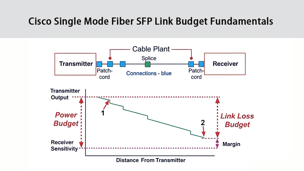
The link budget is a core concept in optical network design, determining whether a fiber connection can transmit data reliably over the desired distance. For Cisco single mode fiber SFP modules, the link budget helps engineers calculate total optical power gained and lost along the fiber path. Comprehending each element of this calculation — transmitter power, receiver sensitivity, and various forms of optical loss — is essential to ensure proper performance of 1310nm and 1550nm links.
Definition of Optical Link Budget
The optical link budget refers to the total allowable signal loss between the transmitter and receiver while still maintaining proper operation. It is calculated as the difference between the transmitter’s output power and the receiver’s minimum sensitivity.
In simple terms, the link budget defines how much loss the system can tolerate across the entire optical path, including fiber, connectors, and splices. If total losses exceed this budget, the link may become unstable or fail entirely.
Key Parameters: Transmit Power and Receiver Sensitivity
Two critical parameters in any Cisco single mode fiber SFP link are transmit power and receiver sensitivity. Transmit power indicates how much optical signal is launched into the fiber, typically measured in dBm. Receiver sensitivity defines the minimum optical power level required for the receiver to correctly interpret the signal.
A higher transmit power or better (lower) receiver sensitivity increases the available link budget. These values are specified in SFP transceiver datasheets and must be carefully matched to ensure compatibility and sufficient performance across the intended distance.
Fiber Loss and Connector Loss Considerations
Even with optimal transmit and receive characteristics, the physical medium introduces losses. Fiber attenuation occurs naturally as light travels through glass material, while connectors and splices add incremental losses at each junction.
Typical single mode fiber has attenuation around 0.35dB/km at 1310nm and 0.20dB/km at 1550nm. Connectors may contribute 0.2 - 0.5dB each, and splices about 0.1dB.
To maintain accurate link design, all these losses are summed and subtracted from the calculated power budget, ensuring that the received signal remains above the receiver’s sensitivity threshold.
Safety Margins in Link Design
A safety margin is an extra buffer added to the link budget to account for uncertainties and future degradation. This includes factors such as aging components, temperature variations, fiber bending, and potential installation imperfections.
Typically, a margin of 2 - 3dB is recommended in Cisco single mode fiber SFP link design. Including this buffer ensures long-term reliability and reduces the risk of intermittent failures, especially in critical network environments.
❇️ Cisco Single Mode Fiber SFP 1G Link Budget Calculations
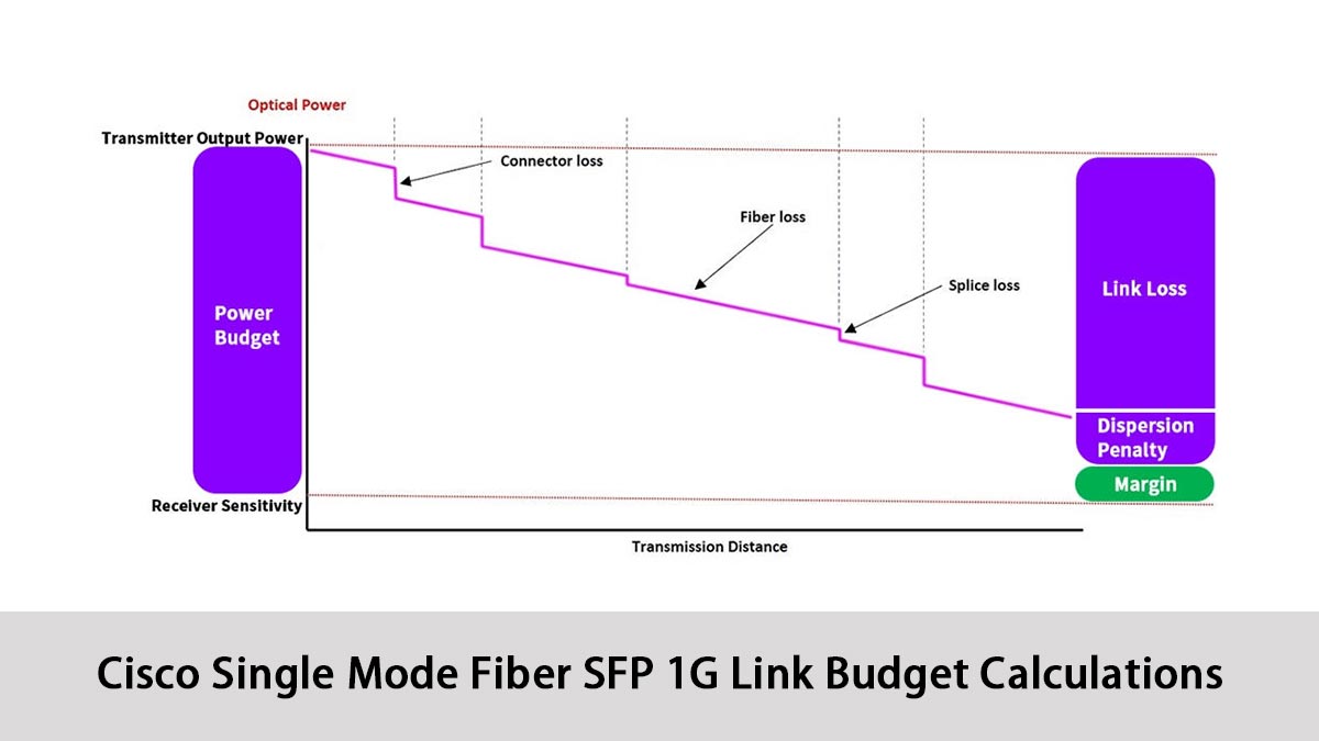
Link budget calculations are critical for ensuring that a Cisco single mode fiber SFP 1G module provides sufficient signal strength over the entire fiber link. By accurately calculating the link budget, network engineers can avoid signal degradation and ensure optimal network performance. This process involves assessing transmit power, fiber losses, and receiver sensitivity.
Step-by-Step Link Budget Calculation Method
To calculate the optical link budget for a Cisco 1G SFP deployment, follow these steps:
- Identify Transmit Power: Determine the optical output power of the SFP module, usually provided in dBm (decibels milliwatts) in the module's datasheet.
- Calculate Fiber Loss: Using the fiber's attenuation factor (dB/km), calculate the total fiber loss by multiplying the attenuation by the total length of the fiber (in km).
- Account for Connector and Splice Losses: Sum the losses from connectors and splices along the optical path. Each connector typically introduces 0.2 to 0.5dB of loss, while splices may have a lower loss.
- Receiver Sensitivity: Find the minimum optical power required by the receiver, also listed in the datasheet, and ensure the received signal meets or exceeds this threshold.
- Calculate Link Margin: Finally, subtract the total losses from the available transmit power. The result should be greater than or equal to the receiver's sensitivity to ensure reliable communication.
By following this method, you can design a link that accommodates the expected losses and provides a robust optical connection.
Example Calculation for 1310nm 1G SFP
Let's assume the following values for a 1310nm 1G Cisco single mode fiber SFP:
- Transmit Power: 0dBm
- Fiber Attenuation: 0.35dB/km
- Fiber Length: 10km
- Connector Loss: 0.2dB per connector, 2 connectors
- Receiver Sensitivity: -20dBm
Calculation:
- Fiber Loss: 0.35dB/km × 10km = 3.5dB
- Connector Loss: 0.2dB × 2 connectors = 0.4dB
- Total Loss: 3.5dB (fiber) + 0.4dB (connectors) = 3.9dB
- Received Power: 0dBm (transmit power) - 3.9dB (total loss) = -3.9dBm
Link Assessment: Since -3.9dBm is greater than the receiver sensitivity of -20dBm, the link is viable. The power margin is 16.1dB (-3.9dBm - (-20dBm)), which provides ample headroom.
Example Calculation for 1550nm 1G SFP
For a 1550nm 1G Cisco single mode fiber SFP with the following parameters:
- Transmit Power: -1dBm
- Fiber Attenuation: 0.2dB/km
- Fiber Length: 40km
- Connector Loss: 0.2dB per connector, 2 connectors
- Receiver Sensitivity: -22dBm
Calculation:
- Fiber Loss: 0.2dB/km × 40km = 8dB
- Connector Loss: 0.2dB × 2 connectors = 0.4dB
- Total Loss: 8dB (fiber) + 0.4dB (connectors) = 8.4dB
- Received Power: -1dBm (transmit power) - 8.4dB (total loss) = -9.4dBm
Link Assessment: Since -9.4dBm is greater than the receiver sensitivity of -22dBm, the link is viable. The power margin is 12.6dB (-9.4dBm - (-22dBm)), which provides ample headroom.
Common Mistakes in Budget Estimation
Some frequent errors occur during link budget planning:
- Ignoring connector quality: Even slight misalignment or contamination can add non-negligible power loss.
- Excluding splice and patch panel loss: Every interface counts toward total attenuation and must be modeled precisely.
- No safety margin: Operating close to theoretical power limits often leads to unstable real-world performance.
Avoiding these pitfalls ensures accurate system design and long-term reliability for fiber networks built on Cisco single mode fiber SFP modules.
❇️ Cisco Single Mode Fiber SFP Transmission Distance Capabilities
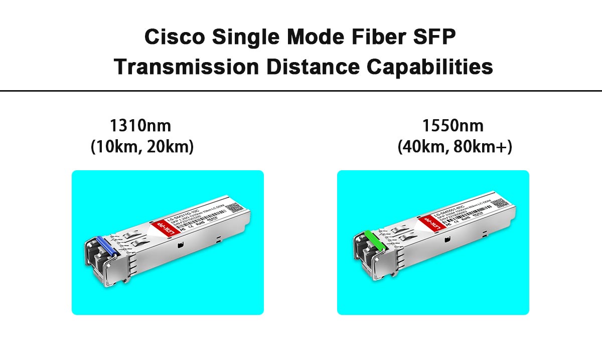
The Cisco single mode fiber SFP transmission distance capabilities define how far a 1G optical signal can travel while remaining within the module’s link budget and power limits. For 1G SFP‑based links, practical distances usually range from 10km up to 80km or more, depending on whether the optics use 1310nm or 1550nm wavelengths and the quality of the fiber infrastructure.
Typical Distance for 1310nm (10km, 20km)
Cisco single mode fiber SFP 1G modules operating at 1310nm are commonly used for short to medium-distance applications. Standard 1000BASE-LX modules (such as Cisco GLC-LH-SM) typically support up to 10km, while enhanced versions (like Cisco GLC-LH-SM-20) can reach up to 20km under optimal conditions.
These modules are widely deployed in enterprise networks, campus backbones, and metropolitan access links. Their performance is stable and predictable, making them a cost-effective choice for environments where ultra-long distances are not required.
Typical Distance for 1550nm (40km, 80km+)
1550nm Cisco single mode fiber SFP 1G modules are designed for long-distance transmission. Standard 1000BASE-ZX modules can support distances of 40km, while higher-power variants (like Cisco GLC-ZX-SM) can extend reach to 80km or even beyond, depending on link conditions.
These modules are commonly used in carrier networks, data center interconnects, and long-haul backbone links. Their lower attenuation characteristics allow signals to travel farther with less power loss, making them ideal for extended-distance deployments.
Impact of Fiber Quality on Distance
While SFP specifications define theoretical maximum distances, actual transmission performance heavily depends on fiber quality. Factors such as fiber type (e.g., G.652 vs G.655), age, installation quality, and environmental conditions can significantly impact achievable distance.
Poor-quality fiber, excessive splicing, dirty connectors, or tight bends can introduce additional loss and reduce effective transmission range. Conversely, high-quality fiber with minimal loss and proper installation can allow links to reach or even exceed their nominal distances.
Therefore, when evaluating Cisco single mode fiber SFP transmission capabilities, it is essential to consider not only the module specifications but also the overall condition and design of the optical infrastructure.
❇️ Cisco Single Mode Fiber SFP 1G Optical Power Levels and Loss Factors
Understanding optical power levels and loss factors is essential for designing reliable Cisco single mode fiber SFP 1G links. Both the transmitter’s output and the receiver’s sensitivity, along with losses in the fiber and connectors, determine the effective reach and stability of the optical link. Accurate knowledge of these parameters ensures optimal link performance and reduces the risk of unexpected failures.
Transmitter Output Power Ranges
The transmitter (Tx) output power of a Cisco single mode SFP 1G module is typically specified as a range in dBm, such as roughly –9dBm to 0dBm for 1310nm SFP modules (e.g., Cisco GLC-LX-SM-RGD) and –5dBm to 0dBm or higher for extended‑reach 40km 1550nm SFP modules.
Higher‑power modules (sometimes reaching 0 to +5dBm) are used where longer spans or extra loss budget are expected, but they must still stay within the receiver’s maximum input power to avoid saturation. In practice, a higher Tx power increases the available link budget and allows more room for fiber and connector losses without dropping below the receiver sensitivity.
Receiver Sensitivity Thresholds
Receiver sensitivity defines the lowest optical power level at which the SFP can still decode the signal with an acceptable bit‑error rate, commonly in the range of –20dBm to –32dBm for 1G Cisco single mode fiber SFP modules.
If the incoming power falls below this threshold — due to excessive fiber length, many splices, or dirty connectors — the link may fail to initialize or become intermittently unstable. Good design practice is to keep the measured Rx power several dB above the minimum sensitivity, preserving a safety margin for aging components and temporary impairments.
Fiber Attenuation per Kilometer
On standard OS1/OS2 single mode fiber, attenuation is wavelength‑dependent: around 0.35dB/km at 1310nm and 0.20dB/km at 1550nm. This means that, for the same distance, a 1550nm link will incur less fiber‑induced loss, which is why these modules can support longer spans (40 to 80+km) compared with 1310nm SFP modules typically rated for 10 - 20km.
When designing a link, the total fiber loss is calculated as “attenuation per km × distance,” and this value must be added to all connector, splice, and margin losses to verify that the Rx power remains within the module’s working range.
Connector and Splice Loss Impact
Connectors and splices introduce additional insertion losses into the optical path:
- Typical connector loss: 0.2 - 0.5dB per connector
- Typical splice loss: 0.1 - 0.3dB per splice
These losses, while small individually, accumulate along the link and must be included in budget calculations. Proper cleaning, alignment, and installation practices can minimize these losses and maintain optimal link performance.
❇️ Cisco Single Mode Fiber SFP Troubleshooting Link Budget Issues
Even with proper planning, Cisco single mode fiber SFP links may experience performance issues due to unexpected losses or mismatched components. Troubleshooting link budget problems requires a systematic approach to identify where signal degradation occurs. By analyzing power levels and physical connections, most issues can be quickly isolated and resolved.
Identifying Power Loss Problems
The first step in troubleshooting is to verify whether excessive power loss is present in the link. This can be done by comparing actual received optical power with the expected values from the link budget calculation.
If the measured power is significantly lower than expected, it indicates additional loss in the system. Common symptoms include intermittent connectivity, high error rates, or complete link failure.
Using Optical Power Meters and OTDR
Optical power meters are commonly used to measure the actual transmit and receive power levels in a fiber link. By testing both ends of the connection, engineers can verify whether the signal strength falls within the acceptable range defined by the Cisco single mode fiber SFP specifications.
For deeper diagnostics, an OTDR (Optical Time-Domain Reflectometer) can be used to analyze the entire fiber path. It helps identify the exact location of issues such as excessive loss, breaks, or abnormal reflections along the cable. This makes it an effective tool for pinpointing faults that are not easily visible during basic inspection.
Diagnosing Connector and Fiber Faults
Physical issues are among the most common causes of link budget problems. Dirty or improperly seated connectors can introduce significant insertion loss. Fiber bends, cracks, or poor-quality splices can also degrade signal quality.
Routine inspection and cleaning of connectors, along with proper cable management, are critical for maintaining optimal performance. Replacing damaged fiber segments or re-terminating connectors often resolves persistent issues.
Resolving Mismatch in SFP Specifications
Another common issue arises from mismatched SFP modules, such as pairing different wavelengths (1310nm and 1550nm) or incompatible power ranges. These mismatches can prevent proper signal detection even if the physical link is intact.
To resolve this, always ensure that both ends of the link use compatible Cisco single mode fiber SFP modules with matching specifications, including wavelength, transmission distance, and supported standards.
❇️ Final Thoughts on Cisco Single Mode Fiber SFP 1310/1550nm 1G Link Budgets
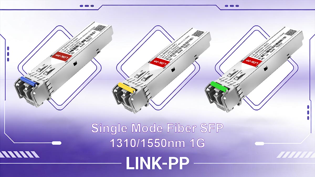
Cisco single mode fiber SFP modules play a vital role in building reliable and scalable optical networks. From understanding wavelength characteristics to accurately calculating link budgets, each factor contributes to overall link performance and stability. Proper planning, combined with careful component selection, ensures that both 1310nm and 1550nm deployments meet their intended distance and reliability requirements.
By mastering link budget fundamentals and applying best practices in design and troubleshooting, network engineers can significantly reduce deployment risks and improve long-term network efficiency. Whether for enterprise, metro, or long-haul applications, choosing the right SFP solution is key to success.
If you are looking for certified and compatible Cisco single mode fiber SFP modules, you can visit the LINK-PP Official Store to browse our full range of tested 1310/1550nm optical transceivers to support your 1G fiber link deployment.