


































Choosing between APC and UPC connectors is a common challenge in fiber optic network design, especially as modern applications demand higher bandwidth, lower latency, and greater signal integrity. While both connector types serve the same fundamental purpose—ensuring efficient light transmission between fiber links—their differences in end-face geometry and reflection performance can significantly impact network reliability and performance.
In practical deployments, the decision between APC vs UPC is not simply a matter of preference. It directly affects return loss, compatibility with existing infrastructure, and suitability for specific scenarios such as FTTH, data centers, or long-distance transmission. Misunderstanding these differences can lead to increased signal degradation, troubleshooting complexity, and even permanent damage to fiber optic SFP module.
This guide explores the key differences between APC and UPC connectors, their technical characteristics, real-world applications, and how to select the right option based on your network requirements. By the end, you will have a clear and actionable understanding of when and why to use each connector type.
? What Are APC and UPC Connectors?
APC and UPC connectors are two common fiber optic connector polishing types, and the key difference lies in how the fiber end-face is finished. This polishing directly determines how much light is reflected back into the fiber, which in turn affects signal quality, especially in high-speed or long-distance networks.
Definition of APC (Angled Physical Contact)
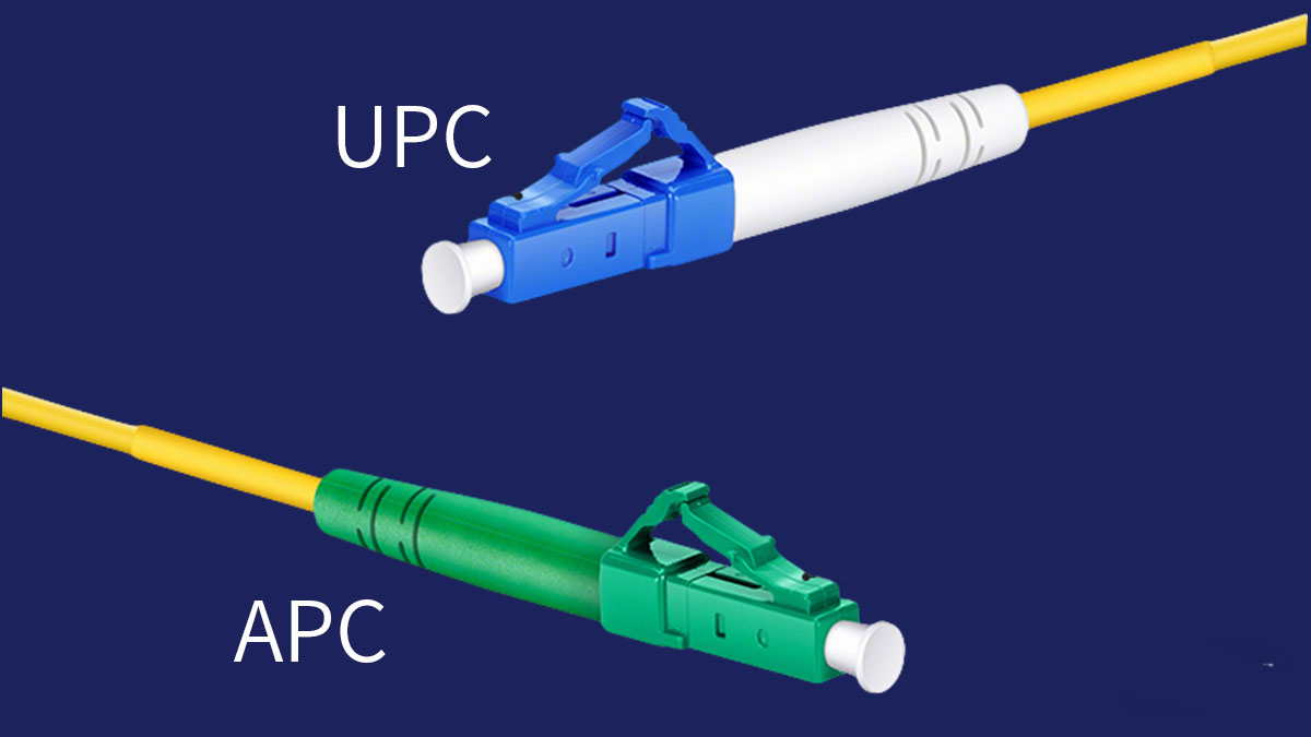
APC connectors use an angled end-face, typically polished at 8 degrees, to significantly reduce back reflection. This design allows reflected light to be directed into the cladding rather than back into the fiber core, improving signal stability.
Key characteristics of APC connectors include:
- 8° angled fiber end-face
- Very low return loss (typically ≥60dB)
- Higher resistance to optical interference
- Commonly identified by green connector housings
From a technical perspective, APC connectors are designed for environments where even minimal reflection can degrade performance, such as analog optical transmission or high-frequency RF-over-fiber systems.
Definition of UPC (Ultra Physical Contact)
UPC connectors feature a flat, ultra-polished end-face that improves upon standard PC (Physical Contact) connectors by reducing air gaps and minimizing insertion loss. However, because the surface is flat, some level of back reflection still occurs.
Key characteristics of UPC connectors include:
- Flat polished fiber end-face
- Moderate return loss (typically ≥50dB)
- Lower manufacturing complexity compared to APC
- Commonly identified by blue connector housings
UPC connectors are widely used in digital optical systems where reflection sensitivity is lower, such as SR transceivers or 10GBASE-R links, making them suitable for general-purpose networking.
Why Connector Polishing Matters in Fiber Optics
The polishing type of a fiber connector directly determines how light behaves at the connection point, making it a critical factor in overall network performance.
The most important impacts of polishing include:
- Reflection control: Poor polishing increases back reflection, which can interfere with transmitted signals
- Signal integrity: Lower reflection leads to cleaner signal transmission, especially in high-speed systems
- Network reliability: Stable optical connections reduce error rates and retransmissions
The comparison below highlights how polishing differences influence performance:
| Parameter | APC Connector | UPC Connector |
|---|---|---|
| End-face angle | 8° angled | Flat (0°) |
| Return loss | ≥60dB | ≥50dB |
| Reflection level | Very low | Moderate |
In practice, the choice between APC and UPC is not about which is universally better, but which is better suited to the specific optical environment and performance requirements.
? APC vs UPC: Core Technical Differences
The core difference between APC and UPC connectors lies in how they handle optical reflection and physical contact at the fiber interface. While both provide low insertion loss and reliable connectivity, APC is optimized for minimizing back reflection, whereas UPC is designed for general-purpose, cost-effective performance.
End-Face Geometry Comparison
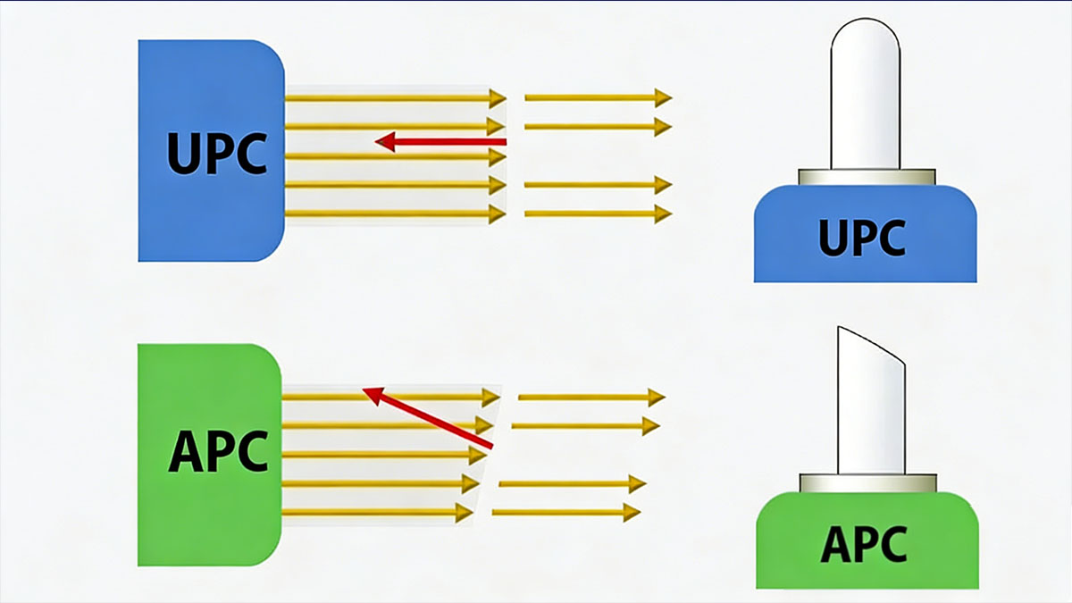
The most fundamental distinction is the geometry of the fiber end-face, which directly influences how light is transmitted and reflected.
The comparison below shows how geometry differs:
| Parameter | APC Connector | UPC Connector |
|---|---|---|
| End-face shape | Angled (8°) | Flat (0°) |
| Contact type | Angled physical contact | Ultra physical contact |
| Reflection path | Redirected to cladding | Reflected back to source |
Because APC connectors use an angled surface, reflected الضوء is deflected away from the fiber core, reducing interference. In contrast, UPC connectors rely on precise flat polishing to minimize, but not eliminate, back reflection.
In practical terms, this means APC is better suited for systems sensitive to reflected signals, while UPC performs well in standard digital environments.
Return Loss (Back Reflection)
APC connectors provide lower back reflection than UPC, making them preferable in high-performance optical systems.
Typical return loss values are:
- APC: ≥60dB
- UPC: ≥50dB
Higher return loss indicates less reflected light returning to the transmitter, which is critical in scenarios such as:
- Analog optical transmission (e.g., RF video)
- High-speed transceivers optical links (e.g., 25G SFP28, 100G QSFP28 or 400G QSFP-DD)
- Long-distance fiber communication
UPC connectors, while slightly higher in reflection, still meet the requirements of most Ethernet and enterprise applications where signal processing can tolerate minor reflections.
Insertion Loss Performance
Both APC and UPC connectors offer similar insertion loss under proper manufacturing and installation conditions, meaning signal attenuation through the connector is generally comparable.
Typical insertion loss ranges:
| Parameter | APC Connector | UPC Connector |
|---|---|---|
| Typical loss | ≤0.3dB | ≤0.3dB |
| Performance range | 0.2–0.3dB | 0.2–0.3dB |
Insertion loss is influenced more by factors such as connector cleanliness, alignment precision, and manufacturing quality than by polishing type alone.
Therefore, in most deployments, insertion loss is not the deciding factor when choosing between APC and UPC.
Signal Quality and Stability
APC connectors provide more stable signal performance in environments where reflection-induced interference is a concern, while UPC connectors are sufficient for most standard digital transmission systems.
Key differences in signal behavior include:
- APC reduces optical return interference, improving signal-to-noise ratio
- UPC may introduce minor reflections, but typically within acceptable limits
- APC is more suitable for analog and RF-based optical systems
- UPC is widely used in packet-based digital networks
From a system design perspective, APC connectors are often selected when signal integrity must be tightly controlled, whereas UPC connectors strike a balance between performance, compatibility, and cost.
? APC vs UPC: Application Scenarios
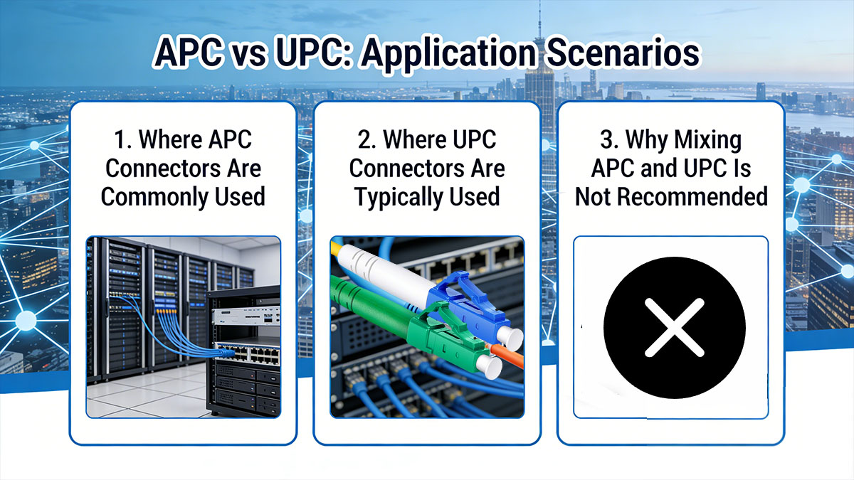
APC connectors are best suited for environments where low reflection is critical, while UPC connectors are widely used in standard digital communication systems where moderate reflection is acceptable. The choice depends on transmission type, distance, and sensitivity to signal interference.
Where APC Connectors Are Commonly Used
APC connectors are primarily deployed in systems that require minimal back reflection to maintain signal integrity, especially in analog or high-frequency optical transmission.
Typical APC application scenarios include:
- FTTH (Fiber to the Home) networks, especially in GPON and EPON architectures using BIDI SFP (like 1G BiDi SFP) to save fiber resources
- Passive Optical Networks (PON), where splitters amplify reflection sensitivity
- RF video and CATV systems that rely on analog signal transmission
- Long-distance optical links where cumulative reflection can degrade performance
These environments benefit from APC’s ability to reduce optical return loss, ensuring stable downstream and upstream signal transmission.
Where UPC Connectors Are Typically Used
UPC connectors are widely used in general-purpose fiber networks where system tolerance for reflection is higher and cost-efficiency is important.
Common UPC deployment scenarios include:
- Ethernet fiber networks using SFP 1G, 10G SFP+, and 25G SFP28 modules
- Data centers and enterprise campus networks, often utilizing multimode transceivers, SX optics, or copper transceivers for short-reach connections
- Short- to medium-distance optical communication
- Optical testing, lab environments, and patching systems
The following comparison highlights typical usage differences:
| Application Type | Preferred Connector | Reason |
|---|---|---|
| FTTH / PON | APC | Low reflection requirement |
| Data center networks | UPC(for Short-range optics like 10G SFP+ or QSFP+ 40G) | Cost-effective and sufficient |
| RF / CATV | APC | Sensitive to signal reflection |
| Enterprise LAN | UPC(for SFP transceiver and copper module deployments) | Standard digital transmission |
In practice, UPC connectors provide a balanced solution for most IT and data communication environments without the need for specialized low-reflection performance.
Why Mixing APC and UPC Is Not Recommended
APC and UPC connectors should never be directly connected because their physical and optical characteristics are incompatible.
Key risks of mixing connectors include:
- Physical mismatch due to angled vs flat end-face
- Increased insertion loss caused by poor contact alignment
- Significant back reflection, leading to signal degradation
- Potential permanent damage to the connector end-face
When an APC connector is mated with a UPC connector, the angled surface prevents proper core alignment, which not only reduces performance but can also scratch or damage the polished surfaces.
To ensure optimal performance and avoid network issues:
- Always match connector types end-to-end
- Clearly label APC (green) and UPC (blue) interfaces
- Verify connector types before installation or patching
Maintaining consistency in connector type is essential for stable and predictable optical network performance.
? Visual and Physical Differences Between APC and UPC
While the technical differences between APC and UPC connectors are critical, visual and physical cues make it easy to identify them during installation and maintenance. Recognizing these differences helps prevent mismatches and ensures consistent network performance.
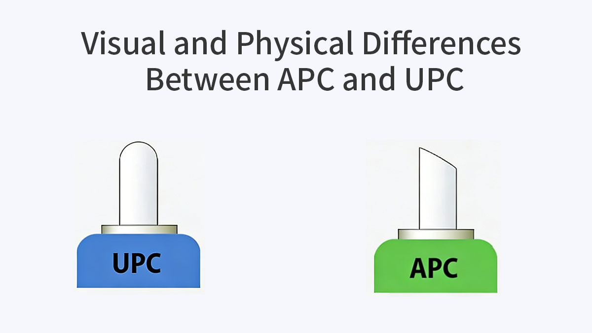
Connector Color Coding Standards
One of the simplest ways to distinguish between APC and UPC connectors is through color coding:
- APC connectors are typically green
- UPC connectors are typically blue
Color coding is an industry standard used to quickly identify connector type, helping technicians avoid incompatible connections during deployment. Some manufacturers may use different shades, but the green vs blue convention is widely adopted in optical networks.
End-Face Inspection and Polishing Quality
Beyond color, the physical end-face of the fiber is a definitive indicator of connector type. Microscopic inspection reveals key differences:
- APC: The end-face is angled at 8°, directing reflected light into the fiber cladding
- UPC: The end-face is flat and highly polished, allowing minimal reflection back into the core
Inspection tools such as fiber microscopes or connector inspection scopes are used to verify proper polishing and end-face quality. Standards compliance (IEC 61754, Telcordia GR-326) ensures that connectors meet industry return loss and insertion loss requirements.
Connector Types Supporting APC and UPC
Both APC and UPC connectors are available in multiple form factors, which can impact compatibility with existing network hardware, including SFP, QSFP, and Fibre Channel modules. Common connector types include:
- SC (Subscriber Connector)
- LC (Lucent Connector)
- FC (Ferrule Connector)
- ST (Straight Tip Connector)
Key considerations:
- Most SC and LC connectors are available in both APC and UPC variants
- FC and ST are more commonly found in legacy or industrial systems
- Connector form factor selection depends on port availability, space constraints, and device compatibility
Using the appropriate connector type ensures secure mechanical fit and optical performance while reducing the risk of mismatches during installation.
By understanding these visual and physical distinctions, technicians and network designers can quickly identify and properly deploy APC and UPC connectors, avoiding common installation errors that lead to reflection issues or performance degradation.
? Performance Comparison: APC vs UPC
When evaluating APC and UPC connectors, the most critical performance factors are return loss, signal stability, and suitability for different network distances. While both connector types offer low insertion loss, their handling of back reflection differentiates their real-world performance.
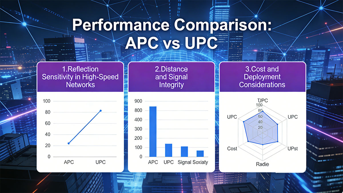
Reflection Sensitivity in High-Speed Networks
APC connectors outperform UPC in scenarios where minimal reflection is essential. The angled end-face of APC connectors directs reflected light into the cladding, reducing interference and maintaining signal integrity.
Key points:
- APC return loss: ≥60dB
- UPC return loss: ≥50dB
- APC is recommended for analog signals, RF-over-fiber systems, and networks operating at high frequencies
- UPC performs adequately for digital systems where minor reflections are tolerated
Using UPC in reflection-sensitive applications can increase error rates, particularly in systems that cannot compensate for optical return loss.
Distance and Signal Integrity
APC connectors provide more stable performance over longer distances due to lower back reflection. UPC connectors are generally sufficient for short- to medium-range links.
Comparison table:
| Parameter | APC Connector | UPC Connector |
|---|---|---|
| Typical maximum distance | Long-haul (>20km) | Short- to medium-range (≤10km) |
| Signal stability | High | Moderate |
| Reflection impact | Minimal | Noticeable in sensitive systems |
For long-haul networks, FTTH deployments, or high-precision measurement systems, APC ensures that cumulative reflection does not degrade signal quality. UPC remains suitable for data center patching where DAC cables, AOC, and short-range multimode transceivers are prevalent and enterprise LANs where distances are shorter.
Cost and Deployment Considerations
While APC connectors generally cost slightly more due to angled polishing and stricter manufacturing tolerances, the performance benefits outweigh the cost in sensitive applications.
Factors influencing connector selection:
- APC: Slightly higher manufacturing cost, critical for reflection-sensitive networks
- UPC: Lower cost, easier to manufacture, ideal for standard digital applications
- Installation practices and cleanliness have a greater effect on insertion loss than connector type alone
In summary, APC connectors are preferred when reflection sensitivity, long-distance stability, or analog signal transmission are critical, while UPC connectors provide sufficient performance for most digital applications with lower cost and simpler deployment requirements.
? How to Choose Between APC and UPC
Selecting the appropriate connector type depends on network requirements, signal sensitivity, and compatibility with existing infrastructure. Making the right choice ensures optimal performance and avoids costly errors or network instability.
Key Decision Factors
When deciding between APC and UPC connectors, consider these primary factors:
- Network type: APC is ideal for FTTH, PON, or RF-over-fiber networks; UPC is suitable for Ethernet, LAN, and general digital networks
- Distance requirements: APC handles long-haul links and high-speed backhaul with minimal reflection; UPC works well for short- to medium-range connections
- Reflection sensitivity: Applications sensitive to back reflection (analog video, high-frequency optical signals) benefit from APC; digital systems with built-in signal tolerance can use UPC
Evaluating these factors first helps narrow the choice based on technical requirements rather than cost alone.
Compatibility With Existing Infrastructure
Connector mismatches can severely degrade network performance. To ensure smooth integration:
- Match connector type end-to-end (APC to APC, UPC to UPC)
- Verify port color coding: green for APC, blue for UPC
- Check device manufacturer specifications for supported connector types
- Avoid mixing connectors in patch panels, splitters, or transceivers
Proper alignment with existing infrastructure reduces insertion loss and prevents reflection-related errors.
Best Practices for Selection
Following best practices ensures reliable performance regardless of connector type:
- Plan the network with consistent connector type throughout each segment
- Clearly label and document APC and UPC connections
- Inspect and clean connectors before installation
- Use quality-tested components that comply with IEC 61754 or Telcordia GR-326 standards
By considering network type, distance, reflection sensitivity, and compatibility, engineers can confidently select the connector type that maximizes performance and reliability while minimizing troubleshooting and maintenance challenges.
? Common Misconceptions About APC vs UPC
Despite widespread use, there are several misconceptions about APC and UPC connectors that can lead to improper network design or installation. Understanding the realities behind these myths helps avoid performance issues and ensures more reliable fiber optic deployments.
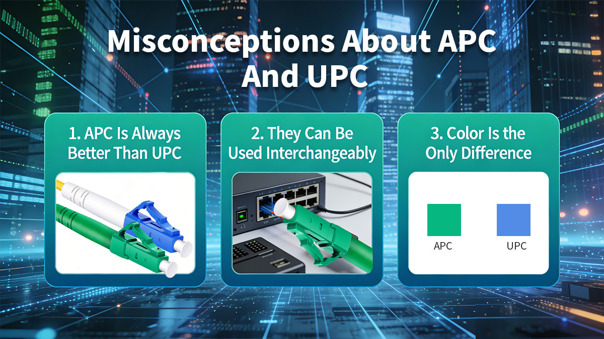
“APC Is Always Better Than UPC”
While APC connectors offer lower back reflection, they are not universally superior. The choice depends on the application:
- APC is advantageous in reflection-sensitive systems such as analog RF, long-haul, or FTTH networks
- UPC is sufficient for most digital networks, data centers, and short-range links where minor reflections do not impact performance
Selecting APC unnecessarily can increase costs without improving network performance in applications that tolerate slight reflection.
“They Can Be Used Interchangeably”
APC and UPC connectors are not compatible due to differences in end-face geometry:
- Mating an APC connector with a UPC connector causes physical misalignment
- Results include higher insertion loss, increased reflection, and potential damage to connector end-faces
- Network reliability can be compromised if connectors are mixed
Maintaining consistent connector types across network segments is essential for predictable performance.
“Color Is the Only Difference”
While APC is typically green and UPC is blue, the true distinction lies in optical and physical characteristics:
- APC uses an angled end-face to redirect reflected light
- UPC has a flat, polished end-face with moderate reflection
- End-face geometry directly affects return loss, signal integrity, and overall network stability
Relying solely on color without understanding underlying technical differences can result in poor performance or connector damage during deployment.
By clarifying these misconceptions, network designers and technicians can make informed decisions, avoid common pitfalls, and ensure that fiber optic systems operate reliably under their intended conditions.
? Future Trends in Fiber Connector Technology
Fiber optic networks continue to evolve rapidly, driven by the demand for higher bandwidth, lower latency, and more reliable connectivity. Connector technology, including APC and UPC types, is adapting to meet these emerging requirements.
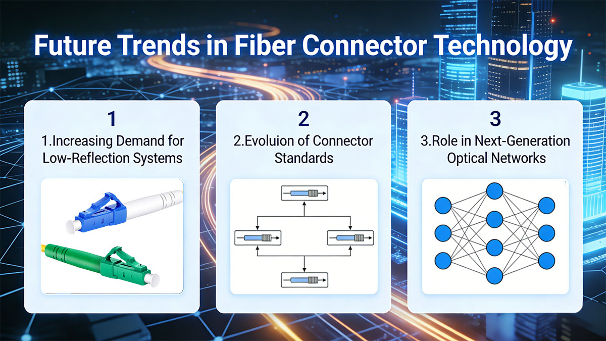
Increasing Demand for Low-Reflection Systems
As networks adopt higher-speed standards such as 25GBASE, 100GBASE, 400GBASE, minimizing back reflection becomes increasingly important:
- High-frequency optical systems and analog RF-over-fiber links require extremely low return loss
- APC connectors or next-generation angled designs will see greater adoption in both access and long-haul networks
- Reflection-sensitive applications, including 5G fronthaul and high-definition video distribution, will drive innovation in connector polishing techniques
This trend emphasizes the need for connectors that maintain performance in environments where even minor reflection can disrupt signal integrity.
Evolution of Connector Standards
Connector manufacturing and industry standards are advancing to improve performance and interoperability:
- Higher precision polishing methods reduce insertion loss and enhance return loss consistency
- Standardization across SC, LC, FC, and ST formats ensures broad compatibility with new optical modules
- Compliance with updated IEC and Telcordia standards ensures that connectors meet the rigorous demands of next-generation networks
These developments make it easier to deploy scalable and reliable networks without frequent hardware upgrades.
Role in Next-Generation Optical Networks
APC and UPC connectors will continue to play a key role in supporting high-bandwidth applications:
- 5G and beyond: Low-reflection connectors are critical for SFP28 25G fronthaul and high-capacity CWDM/DWDM SFP backhaul links
- Data center interconnects: Consistent performance at higher speeds ensures minimal signal degradation
- Emerging optical services: Advanced video streaming, cloud computing, and AI-driven applications require stable, low-loss connections
As optical networks expand in speed and complexity, connector performance becomes a decisive factor in network reliability, efficiency, and scalability.
The future of fiber connector technology lies in improving signal integrity, supporting higher data rates, and ensuring compatibility across diverse network applications. APC and UPC connectors, along with evolving standards, will remain central to achieving these goals.
? FAQs About APC vs UPC
What is the main difference between APC and UPC?
APC connectors have an angled end-face to reduce back reflection, while UPC connectors have a flat, polished end-face with moderate reflection.
Can APC and UPC connectors be connected together?
No, mating APC with UPC causes misalignment, higher insertion loss, and potential connector damage.
Which connector is better for FTTH networks?
APC is preferred due to its low reflection and better performance in long-distance optical links.
How can I visually identify APC vs UPC connectors?
APC connectors are typically green, and UPC connectors are typically blue, reflecting their polishing type.
Does connector type affect insertion loss significantly?
Not significantly; insertion loss is similar for both APC and UPC when properly manufactured and installed.
Are APC connectors necessary for short-distance networks?
Usually not; UPC connectors are sufficient for short-range digital networks where reflection is less critical.
Do APC connectors cost more than UPC?
Yes, APC connectors are generally slightly more expensive due to angled polishing and tighter manufacturing tolerances.
Can I use APC connectors in a data center?
Yes, but UPC is usually sufficient unless the network has high-speed or reflection-sensitive applications.
? Conclusion
Choosing the right fiber connector type is essential for ensuring reliable network performance. APC connectors excel in applications where low reflection and signal stability are critical, such as FTTH, PON, and long-distance or analog optical systems. UPC connectors, on the other hand, are well-suited for standard digital networks, short- to medium-range links, and data center environments where minor reflections are acceptable. By understanding the technical differences, application scenarios, and compatibility considerations, network designers can make informed decisions that optimize performance and reduce maintenance issues.
Explore a wide range of high-quality optical transceivers at the LINK-PP Official Store to support reliable APC and UPC fiber connections in your network.







