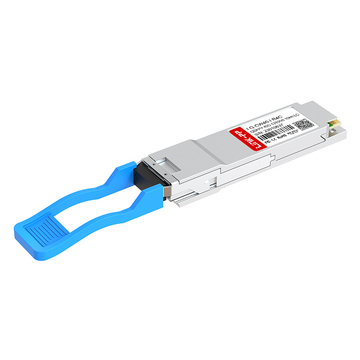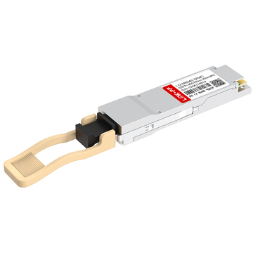
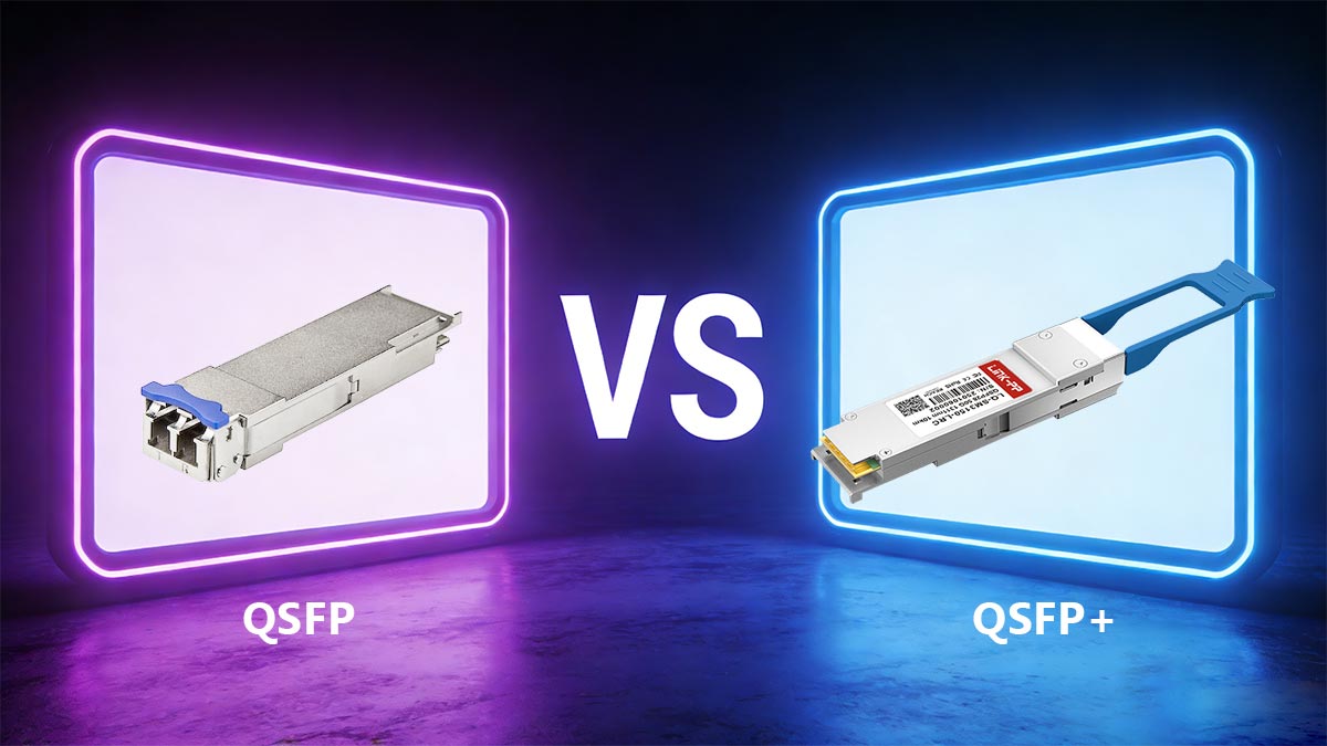
As los centros de datos face an unprecedented demand for higher ancho de banda, understanding the evolution of transceptores ópticos becomes essential, especially when comparing QSFP vs QSFP +. While the original Quad Small Form-factor Pluggable (QSFP) laid the groundwork for high-density networking, it was the arrival of QSFP+ that truly revolutionized the industry by meeting the demanding 40G Ethernet estándar.
This technological leap was achieved by upgrading to a 4-lane architecture that delivers a powerful aggregate throughput of 40Gbps. In this guide, we will decode the physical and architectural differences between QSFP vs QSFP+, exploring how this evolution shaped modern 40G infrastructure and paved the way for future high-speed networking.
🎈 El hito de los 40G: Introducción a QSFP frente a QSFP+
Con el auge del tráfico en los centros de datos a principios de la década de 2010, se hizo urgente la necesidad de un módulo enchufable compacto y de alta velocidad capaz de ofrecer Ethernet de 40 Gigabit de forma fiable. Dos formatos ópticos —QSFP y su sucesor mejorado, QSFP+— surgieron como las principales soluciones, aunque sus similitudes suelen generar confusión. Comprender la evolución de QSFP frente a QSFP+ es fundamental para cualquiera que evalúe infraestructuras heredadas o planifique actualizaciones graduales de la red.
La creciente demanda de mayor ancho de banda en los centros de datos
By 2010, traditional 10G links were struggling to keep pace with la computación en nube, video streaming, and large-scale virtualización. Server-to-switch connections became congested, forcing network architects to seek a cost-effective leap in bandwidth without drastically increasing physical port density. When comparing the historical bottleneck of QSFP vs QSFP+, the industry desperately needed a module that could deliver four times the throughput of a single 10G channel while maintaining compatibilidad con versiones anteriores with existing cabling plants.
Definición del origen del módulo QSFP (Quad Small Form-factor Pluggable)
The original QSFP, introduced under the Multi-Source Agreement (Contratos regionales) in 2006, was designed as a four-lane electrical interface, each lane running up to 10Gbps, for a theoretical aggregate of 40 Gbps. However, early Módulos QSFP were primarily deployed for InfiniBand SDR (2.5Gbps per lane) and DDR (5Gbps per lane) applications, not for 40G Ethernet. This functional gap highlights the early performance differences of QSFP vs QSFP+, though the early design was highly praised for its compact size — about 30% smaller than a traditional XFP transceptor — allowing up to 36 ports on a single line card.
Cómo evolucionó QSFP+ para cumplir con el estándar Ethernet de 40G
Cuando la característica IEEE802.3ba standard ratified 40GBASE-R in 2010, the original QSFP’s per-lane electrical signaling (typically 2.5G or 5G) was insufficient. The QSFP+ revision upgraded each of the four electrical lanes to reliably run at 10Gbps, using improved signal integrity and stricter impedance control. This core architectural difference is central to the QSFP vs QSFP+ transition, allowing the enhanced module to carry four 10G lanes in parallel, aggregating to a true 40G while keeping the same external form factor and latching mechanism as its predecessor.
Alcance de la comparación: Características de QSFP frente a QSFP+
Para evitar confusiones, conviene comparar directamente las especificaciones técnicas clave que distinguen el QSFP original del QSFP+ con capacidad de 40G. Un análisis comparativo entre QSFP y QSFP+ revela con precisión la posición de cada módulo en cuanto a velocidad de datos, cumplimiento de estándares y casos de uso típicos.
La siguiente tabla resume estos parámetros técnicos críticos para ilustrar cómo evolucionó el hardware para satisfacer las demandas de los centros de datos modernos:
| Elemento | QSFP original | QSFP + |
| Tarifa eléctrica máxima por carril | 2.5 - 5 Gbps (InfiniBand) | 10 Gbps (Ethernet 40G) |
| Ancho de banda total agregado | Hasta 20 Gbps (4 x 5G) | 40 Gbps (4 x 10 G) |
| Aplicaciones principales | InfiniBand SDR/DDR, enlaces propietarios iniciales | 40GBASE-SR4, 40GBASE-LR4, Ethernet de 40G |
| Cumplimiento con IEEE 802.3ba | No | Sí (para 40G) |
Como se muestra en la tabla, al analizar QSFP frente a QSFP+, la versión más reciente es esencialmente una variante con rendimiento mejorado: idéntica en tamaño físico, pero con especificaciones eléctricas más estrictas para alcanzar velocidades de 40G. En adelante, nuestra comparación se centrará exclusivamente en estas dos variantes en relación con la infraestructura de 40G.
🎈 Descifrando la arquitectura: Evolución física de QSFP frente a QSFP+
While the performance leap from early data rates to 40G networking is impressive, it heavily relied on critical hardware changes. Examining the physical architecture reveals how engineers modified the internal components while preserving the external shape of the transceiver. These precise hardware adjustments successfully eliminated data bottlenecks without requiring data centers to replace their existing cambiar chasis.
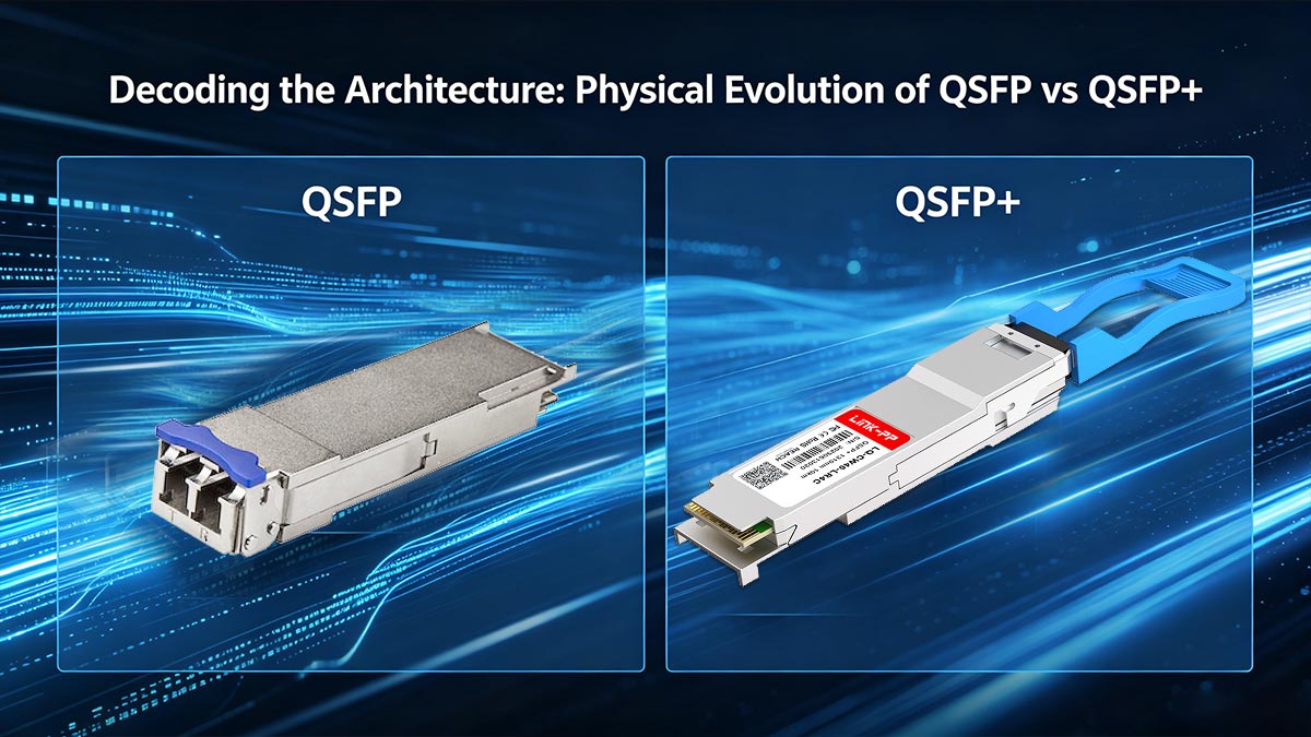
Comparación de las dimensiones del factor de forma y las disposiciones mecánicas
Desde una perspectiva externa, el diseño estructural de QSFP y QSFP+ presenta dimensiones mecánicas idénticas. Ambos módulos utilizan la misma anchura, altura y profundidad de conexión de la carcasa metálica para garantizar una compatibilidad total con las jaulas de equipos físicos existentes.
Sin embargo, internamente, la estructura se optimizó para dar cabida a componentes electrónicos más rápidos. Los materiales de la carcasa y el blindaje interno se mejoraron discretamente para garantizar una durabilidad física a largo plazo al funcionar a altas velocidades.
Cómo el diseño de pines facilita el salto a 40G
The gold finger pin design on the internal placa de circuito impreso (PCB) is where a critical evolution occurred. Although both modules utilize a standard 38-pin layout, the enhanced variant features a radically optimized electrical pin configuration to prevent cross-lane interference.
Mediante el rediseño de los pines de tierra y los pares de señales diferenciales de alta velocidad, los ingenieros lograron minimizar la capacitancia parásita. Esta precisa optimización del diseño proporcionó la ruta eléctrica limpia necesaria para aumentar de forma segura la velocidad de cada carril hasta 10 Gbps.
Mejoras en la gestión térmica y la disipación del calor.
El funcionamiento de cuatro carriles paralelos a 10 Gbps genera mucho más calor que las primeras operaciones de InfiniBand a baja velocidad. Para evitar fallos en los componentes, los módulos más recientes incorporaron diseños térmicos avanzados, que incluyen disipadores de calor integrados especializados y rutas de disipación de calor con nervaduras.
Además, se mejoró la aleación estructural metálica utilizada en la carcasa para proporcionar una conductividad térmica mucho mayor. Estos cambios permiten que el calor se disipe rápidamente en el flujo de aire de refrigeración del conmutador, evitando que los puntos calientes localizados degraden el rendimiento de la red.
Perfiles de consumo de energía de QSFP frente a QSFP+
The power consumption profile experienced a necessary shift as hardware capabilities transitioned from early designs to the 40G-optimized standard. Original low-speed modules operated under highly conservative presupuestos de energía, as their simpler internal circuitry required very little electrical current to maintain signal integrity.
With the arrival of the higher-speed standard, internal components like Recuperación de reloj y datos (CDR) chips and advanced optical lasers demanded additional power to operate. To manage this safely, the updated specification introduced structured power classes, ensuring that modern network switches can properly allocate the necessary power and cooling resources for each plugged-in module.
🎈 Análisis de la arquitectura de carriles: QSFP frente a QSFP+ para transmisión de 40G
La verdadera potencia de la transmisión 40G reside en la arquitectura interna de canales del módulo transceptor. Al dividir los flujos de datos de alta velocidad en múltiples rutas paralelas, estos componentes logran un rendimiento masivo sin aumentar el tamaño del hardware. El análisis de esta configuración interna revela cómo evolucionó el enrutamiento de datos para gestionar con fluidez el tráfico de las redes de próxima generación.
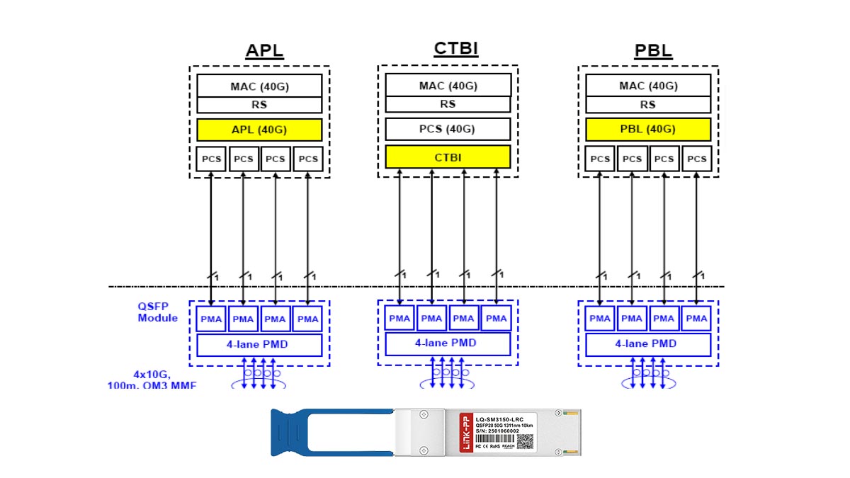
La arquitectura de 4 carriles (4 x 10 Gbps) de QSFP+
El módulo QSFP+ alcanza su impresionante velocidad de 40G gracias a un diseño de procesamiento paralelo de alta eficiencia. En lugar de depender de un único canal serie ultrarrápido, divide los datos en cuatro canales de transmisión (TX) y cuatro de recepción (RX) independientes.
Los siguientes puntos clave destacan cómo funciona esta configuración específica de cuatro carriles:
- Diseño de cuatro carriles: Utiliza cuatro carriles eléctricos independientes simultáneamente.
- 10G por carril: Cada carril individual transmite datos a 10 Gbps.
- Agregación de datos: Combina los 4 carriles para lograr un total real de 40 Gbps.
- Óptica paralela: Drives multi-fiber cables to send data over the same distance.
Por qué los límites de velocidad por carril originales de QSFP no alcanzaron los 40G
La arquitectura QSFP original nunca se diseñó para soportar las exigencias de las redes Ethernet de 40G. Sus circuitos internos se construyeron para estándares antiguos de baja velocidad que alcanzaron su límite mucho antes de cumplir con los requisitos de los centros de datos modernos.
Diversas limitaciones técnicas impidieron que el módulo original alcanzara el hito de los 40G:
- Velocidades bajas por carril: Los límites por carril están limitados a un máximo de 2.5 Gbps o 5 Gbps.
- Cuellos de botella en el circuito: Los chips internos no podían procesar frecuencias más altas.
- Límite de ancho de banda total: La salida total combinada solo alcanzó entre 10 Gbps y 20 Gbps.
- Enfoque de InfiniBand: Diseñado principalmente para la agrupación en clústeres inicial, no para Ethernet de alta velocidad.
Integridad de la señal y rendimiento del diagrama de ojo a velocidades más altas
Aumentar la velocidad de cada canal a 10 Gbps genera importantes problemas de ruido eléctrico y degradación de la señal. Los ingenieros de redes utilizan diagramas de ojo —una herramienta visual para medir la distorsión de los datos— para garantizar que el módulo QSFP+ transmita datos limpios y sin errores.
Para lograr un "ojo abierto" amplio y estable en el diagrama se requieren varias características de ingeniería avanzadas:
- Control de impedancia: Adapta la resistencia eléctrica para evitar reflexiones de la señal.
- Crosstalk isolation: Prevents electrical noise from leaking between parallel lanes.
- Reducción de fluctuaciones: Mantiene la sincronización de datos perfectamente estable en todos los canales.
- Rutas de datos despejadas: Garantiza la entrega de datos sin errores a la máxima velocidad.
Rendimiento de transferencia de datos agregada en redes conmutadas de alta densidad
En entornos de conmutación de alta densidad, apilar docenas de puertos de 40G supone una enorme carga para la red. El rendimiento agregado de QSFP+ garantiza que los conmutadores puedan procesar terabytes de datos sin generar atascos localizados.
Esta agregación de alta densidad ofrece varias ventajas de rendimiento para la red en general:
- Elimina los cuellos de botella: Mantiene la transmisión de datos fluida entre los conmutadores principales.
- Maximiza el espacio en el rack: concentra un ancho de banda masivo en una sola unidad de rack.
- Equilibra el tráfico: Distribuye las cargas de datos de manera uniforme entre rutas paralelas.
- Escalabilidad eficiente: Permite a los centros de datos ampliar su capacidad sin problemas.
🎈 Compatibilidad con protocolos y estándares: Evolución de QSFP frente a QSFP+
Las diferencias técnicas entre las distintas generaciones de hardware se hacen evidentes al analizar los protocolos de red y los estándares industriales que admiten. Si bien los primeros transceptores se diseñaron para aplicaciones específicas de almacenamiento de datos y agrupación en clústeres, sus sucesores se extendieron a las redes empresariales a gran escala. El seguimiento de este historial de cumplimiento normativo revela cómo la industria se alineó bajo un marco unificado para garantizar una compatibilidad global impecable.
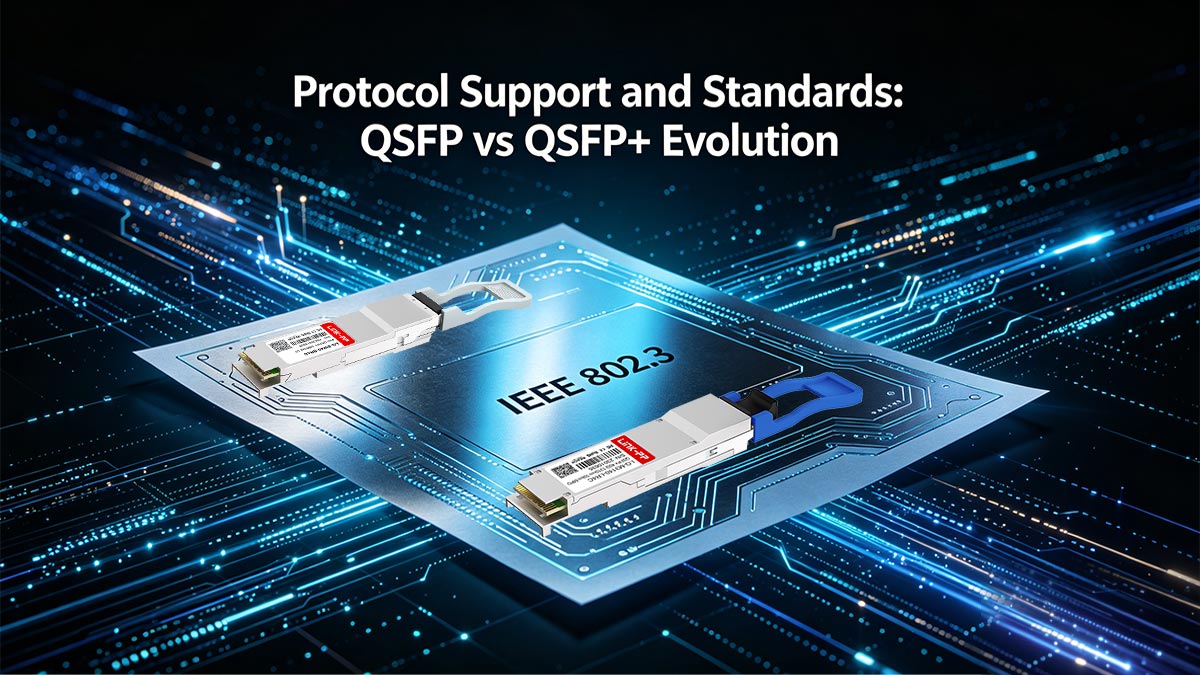
Cumplimiento del estándar Ethernet IEEE 802.3 de 40 Gb
La divergencia más significativa en la cronología de QSFP vs. QSFP+ radica en el cumplimiento oficial con los estándares Ethernet convencionales. El módulo QSFP original se diseñó antes de que la industria finalizara su hoja de ruta para las redes de 40G, lo que lo dejó sin un marco Ethernet estandarizado que seguir.
En cambio, el módulo QSFP+ mejorado se diseñó específicamente para cumplir con el estándar IEEE 802.3ba de Ethernet de 40 Gbps. Esta certificación crucial garantizó que los módulos más recientes pudieran admitir ópticas estandarizadas 40GBASE-SR4 y 40GBASE-LR4, lo que los hace universalmente compatibles entre diferentes fabricantes.
Compatibilidad con InfiniBand SDR, DDR, QDR y FDR
Al comparar el rendimiento de QSFP frente a QSFP+, su historial con los protocolos InfiniBand pone de manifiesto un importante salto generacional. Los módulos QSFP más antiguos manejaban principalmente los primeros protocolos InfiniBand de velocidad de datos simple (SDR) y doble (DDR), que alcanzaban velocidades relativamente bajas.
Con la transición de la tecnología a QSFP+, la compatibilidad se amplió para incluir los perfiles InfiniBand Quad Data Rate (QDR) y Fourteen Data Rate (FDR). Fundamentalmente, si bien QSFP+ permitió alcanzar estas velocidades superiores, también mantuvo la compatibilidad total con los protocolos SDR y DDR anteriores para garantizar una migración de red sin problemas.
Integración de Fiber Channel Over Ethernet (FCoE)
A medida que las redes de almacenamiento convergieron con las redes IP tradicionales, los transceptores tuvieron que evolucionar para transportar múltiples tipos de tráfico simultáneamente. El QSFP original carecía del ancho de banda y las especificaciones eléctricas necesarias para procesar eficientemente estas cargas de trabajo de almacenamiento densas y combinadas a las velocidades actuales.
With the development of QSFP+, transmitting both standard LAN data and heavy SAN storage traffic through the exact same physical port became possible. However, it is important to note that this Fiber Channel over Ethernet (FCoE) integration relies heavily on the capabilities of the host equipment — such as converged network adapters (CNAs) and specialized switches — rather than being an inherent feature of the QSFP+ module itself.
Directrices del Acuerdo Multisource (MSA) para QSFP frente a QSFP+
Las directrices fundamentales para ambos módulos se rigen por Acuerdos de Múltiples Proveedores (MSA, por sus siglas en inglés), que garantizan que diferentes fabricantes produzcan hardware físicamente compatible. El MSA INF-8438 inicial estableció la huella física básica para el QSFP original, pero dejó margen para limitaciones eléctricas.
To push boundaries, manufacturers collaborated on the updated SFF-8436 specification to define the strict parameters for QSFP+. For advanced diagnostics, this newer agreement inherited and integrated the Digital Diagnostics Monitoring (DDM) features originally defined by the SFF-8472 standard, standardizing the comprehensive telemetry that defines the modern QSFP vs QSFP+ framework.
🎈 Evolución de cables y medios: conectividad QSFP frente a QSFP+
The shift in transmission speeds drastically changed the underlying cabling infrastructure required to connect network hardware. As transceivers jumped from low-speed clustering links to high-density 40G aggregates, traditional cordones de parche could no longer keep pace. Exploring the media evolution reveals how advanced fiber termination and clever wavelength management enabled seamless structural links across the data center floor.
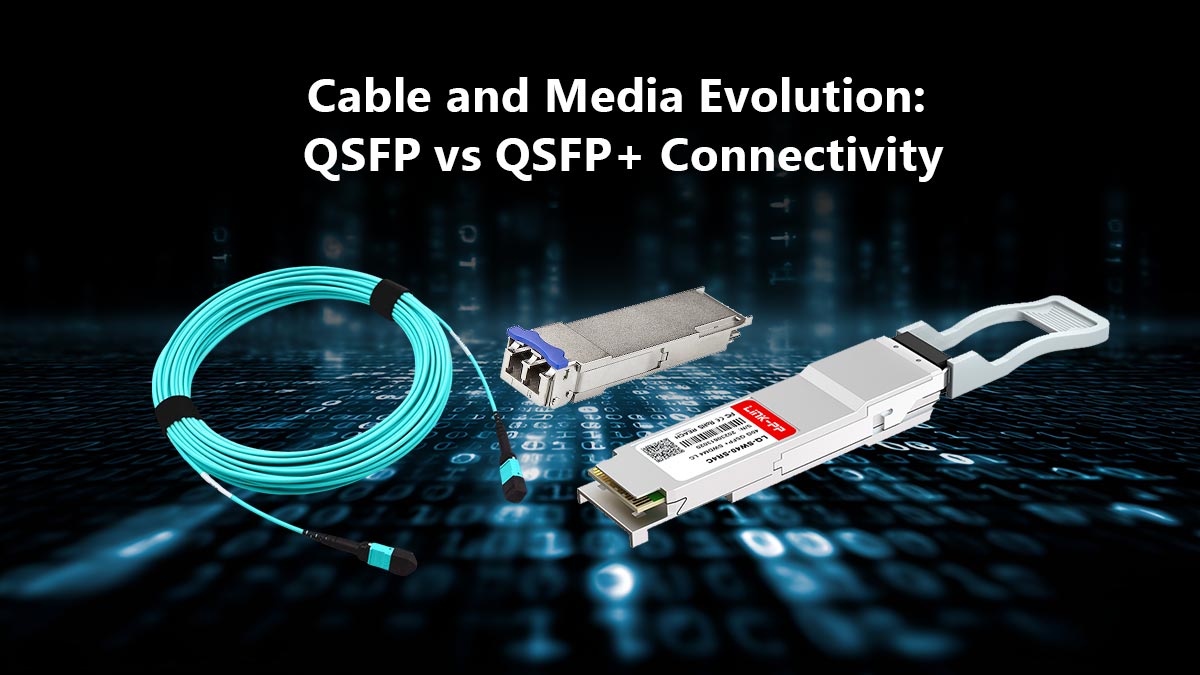
El cambio a la óptica paralela MTP/MPO para transceptores ópticos de 40G
Al comparar las interfaces de fibra de QSFP y QSFP+, el cambio más visible se produjo con la adopción generalizada de la óptica paralela. Los transceptores monocanal tradicionales se basaban en conexiones de doble fibra sencillas, pero la arquitectura multicanal de 40G requería un enfoque diferente.
To support the four discrete data lanes of the QSFP+ standard, engineers turned to MTP / MPO connectors, which bundle 12 separate fibers into a single compact plug. This allowed the module to use four fibers for transmitting and another four for receiving simultaneously, establishing a reliable multi-lane parallel optical connection.
Soluciones QSFP+ avanzadas: Dúplex LC y el auge de los módulos 40G BiDi
While MTP/MPO cabling provided the ideal physical highway for datos paralelos, upgrading an entire data center's fiber backbone can be incredibly expensive. This infrastructure challenge sparked a major design divergence in the QSFP vs QSFP+ ecosystem, leading to the creation of advanced 40G BiDi (Bidirectional) transceivers.
Unlike early hardware configurations, 40G Módulos BiDi utilizar un LC dúplex connector interface, allowing them to run over existing 10G fibra multimodo patches. By transmitting multiple wavelengths over just two fibers, these clever optics saved organizations from costly cable overhauls during their 40G network migrations.
Mejoras en el alcance de la fibra monomodo frente a la fibra multimodo en QSFP+
Distance requirements dictate whether an enterprise deploys multimode or fibra monomodo media. Early QSFP layouts were largely confined to short-reach, local clustering fabrics with highly restricted distance capabilities.
The development of the QSFP+ standard brought massive reach enhancements, dividing deployment options between cost-effective multimode fiber (MMF) for short runs and single-mode fiber (SMF) for long-distance backbones. Short-range modules (such as the QSFP-40G-SR4) easily cover distances up to 150m over OM4 cables, while long-range variants (like the QSFP-40G-LR4) utilize high-powered lasers to push data up to 10km without signal degradation.
Integración de la multiplexación por división de longitud de onda (WDM) en la óptica de 40G.
To achieve long-distance transmission over a single pair of single-mode fibers without using bulky parallel cables, engineers integrated Wavelength Division Multiplexing (WDM) into the hardware design. This sophisticated optical technology was practically non-existent in the early, low-speed era of original QSFP designs.
Dentro de un módulo 40GBASE-LR4 QSFP+, un multiplexor interno combina cuatro flujos de datos independientes en cuatro longitudes de onda ópticas distintas, alrededor de los 1310 nm. Estas cuatro señales viajan simultáneamente a través de una sola fibra óptica y se separan de forma precisa mediante un demultiplexor en el extremo receptor, lo que maximiza la eficiencia de los datos sin aumentar la cantidad de cables físicos.
🎈 Aplicaciones en el mundo real: Implementación de QSFP frente a QSFP+ en infraestructura de 40G
El verdadero valor de cualquier estándar de hardware se hace evidente al evaluar su implementación en redes de producción reales. A medida que los centros de datos se esforzaban por gestionar el enorme volumen de tráfico, la elección de los componentes ópticos adecuados determinaba tanto el rendimiento de la red como los costes operativos. El análisis de casos de uso reales revela cómo las organizaciones reemplazaron sistemáticamente las interconexiones obsoletas para construir entornos operativos de 40G robustos.
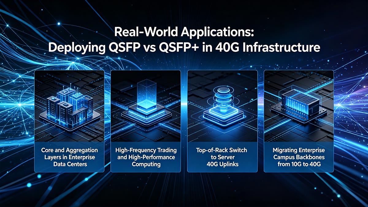
Capas de núcleo y agregación en centros de datos empresariales
En los grandes centros de datos empresariales, la gestión del tráfico masivo que circula entre los conmutadores de la capa central y la capa de agregación requiere un rendimiento de datos increíble. Si bien los primeros diseños se basaban en el QSFP original para agrupar múltiples conexiones de baja velocidad, este enfoque pronto resultó insuficiente para las exigencias de la virtualización moderna.
La implementación de módulos QSFP+ optimizados para 40G permitió a los administradores de centros de datos agregar tráfico pesado en canales de alta eficiencia. Este cambio de ingeniería simplificó enormemente el enrutamiento de datos entre los conmutadores centrales, garantizando que el tráfico de aplicaciones de alto volumen se transmita a través del núcleo de la red corporativa sin sufrir pérdidas de paquetes ni retrasos estructurales.
Negociación de alta frecuencia y computación de alto rendimiento (HPC)
Informática de alto rendimiento (HPC) environments and high-frequency trading networks operate under incredibly tight processing deadlines where microsecond delays translate to millions of dollars. When evaluating QSFP vs QSFP+ inside these advanced clustering environments, the technical differences became critical.
Las instalaciones de computación de alto rendimiento (HPC) prefieren el estándar QSFP+ mejorado, ya que admite los protocolos InfiniBand QDR y FDR de alta velocidad con rutas eléctricas optimizadas de baja latencia. Estas características de rendimiento permiten que los clústeres de computación masivos compartan datos casi instantáneamente, evitando los cuellos de botella de transmisión que afectaban a las primeras instalaciones de hardware de baja velocidad.
Conmutador Top-of-Rack (ToR) a enlaces ascendentes de servidor de 40G
As individual physical servers grew more powerful, their uplink connections to the local Top-of-Rack (ToR) switch required a massive boost in available throughput. The old method of combining multiple 10G links consumed too many physical ports and complicated basic network architecture.
La integración de interfaces QSFP+ de alta densidad en las tarjetas de línea de los conmutadores ToR solucionó eficazmente este problema de densidad. Permitió a los ingenieros de red implementar enlaces ascendentes de 40G de alta eficiencia desde el rack de servidores directamente a la capa de agregación, maximizando el ancho de banda disponible y ahorrando valioso espacio en los equipos.
Migración de redes troncales empresariales de campus de 10G a 40G
Migrar una extensa red corporativa desde una troncal de 10G congestionada representa un importante obstáculo logístico y financiero para los departamentos de TI. En el contexto de la transición de QSFP a QSFP+, el módulo mejorado proporcionó las herramientas operativas precisas necesarias para gestionar sin problemas estas actualizaciones arquitectónicas de gran alcance.
Mediante el uso de transceptores flexibles 40G BiDi o LR4 QSFP+, los administradores de red lograron aumentar la velocidad de sus enlaces troncales a 40G a través de las rutas de fibra óptica existentes. Este ingenioso método evitó el elevado coste de instalar nueva fibra a través de las paredes del campus, reduciendo drásticamente los costes de instalación y minimizando el tiempo de inactividad de la red durante las actualizaciones estructurales críticas.
🎈 Más allá de 40G: El legado futuro de QSFP frente a QSFP+
Las innovaciones arquitectónicas implementadas durante la migración a 40G crearon un modelo duradero para el futuro del hardware de redes de alta velocidad. Al analizar cómo evolucionó este marco específico de cuatro carriles a lo largo del tiempo, podemos observar claramente cómo la industria sentó las bases para los modernos centros de datos de terabits.
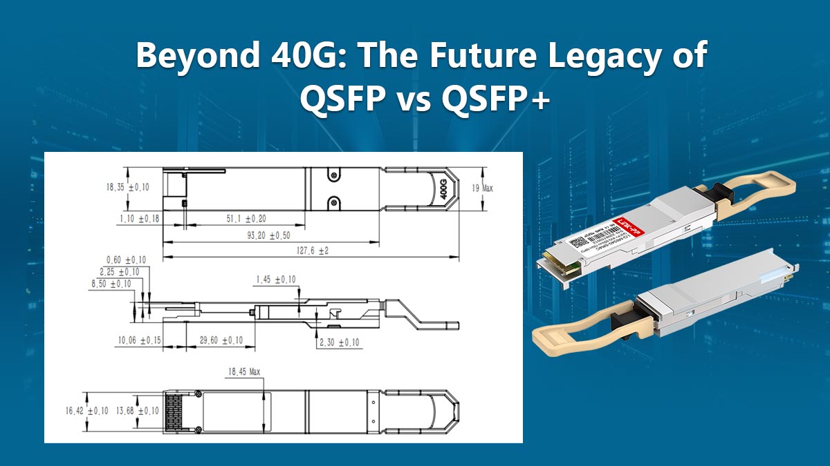
Cómo el formato 40G QSFP+ sentó las bases para el 100G QSFP28
When analyzing the legacy of QSFP vs QSFP+, the most profound impact was how the 40G mechanical footprint paved the direct path for 100G QSFP28 modules. By maintaining the exact same outer dimensions but upgrading the internal lanes from 10Gbps to 25Gbps, engineers achieved a massive speed quadrupling without changing switch port sizes.
La evolución de la señalización NRZ a PAM4: escalando más allá de los límites de 40G
While the QSFP vs QSFP+ era relied entirely on traditional Non-Return-to-Zero (NRZ) signaling to transmit binary ones and zeros, this electrical method eventually hit a strict physical performance wall. To scale past these 40G and 100G limits, modern hardware transitioned to Pulse Amplitude Modulation 4-Level (PAM4) signaling, which packs twice as much data into the same time slot by using four distinct voltage levels.
Comparación de la arquitectura de 4 carriles: De 40G QSFP+ a 200G/400G QSFP-DD
The foundational four-lane architecture popularized during the QSFP vs QSFP+ transition remains highly relevant in today's ultra-fast 200G and 400G networks. Modern QSFP-DD (Double Density) transceivers expand upon this exact same structural heritage by adding a second row of electrical pins, doubling the lane count to eight to achieve unprecedented data center density.
🎈 Conclusiones clave de la evolución de los módulos QSFP frente a QSFP+ de 40 G
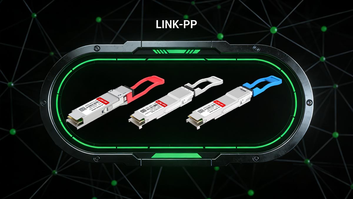
En resumen, al analizar la historia de QSFP frente a QSFP+, se pone de manifiesto cómo las ingeniosas mejoras internas pueden aumentar drásticamente el rendimiento de la red sin modificar el tamaño físico del hardware. Si bien el diseño original introdujo una densidad espacial altamente eficiente, fueron las estrictas mejoras eléctricas y el procesamiento paralelo de 4 carriles de QSFP+ los que realmente convirtieron el despliegue de 40G de alta velocidad en un estándar global.
Elegir los componentes ópticos adecuados es absolutamente fundamental para garantizar la fiabilidad de la red a largo plazo, una eficiencia energética óptima y una escalabilidad futura sin problemas. Si actualmente está actualizando la infraestructura de su centro de datos u optimizando sus conmutadores empresariales, explore la selección premium de transceptores ópticos de alto rendimiento en LINK-PP Tienda Oficial para encontrar la solución perfecta para sus necesidades.