


































Modern communication networks rely heavily on fiber optic technology to deliver high-speed, low-latency, and high-capacity data transmission. From data centers and enterprise campuses to long-haul telecommunications infrastructure, optical fibers serve as the backbone of digital connectivity. As transmission speeds continue to increase, maintaining signal quality across fiber links has become a critical factor in ensuring reliable network performance.
One of the most important challenges affecting optical communication is attenuation in fiber optics. Attenuation refers to the gradual loss of optical signal power as light travels through a fiber cable. Excessive attenuation can shorten transmission distances, increase error rates, and reduce overall network efficiency. Understanding the sources of signal loss and the methods used to recover or maintain signal strength is essential for network engineers, system integrators, and IT professionals.
This guide explores several key aspects of attenuation in fiber optic systems, including:
-
The definition and fundamentals of optical attenuation
-
Common causes of signal loss in fiber networks
-
Differences in attenuation across fiber types and wavelengths
-
Measurement techniques such as optical power testing and OTDR analysis
-
Practical signal recovery methods and attenuation reduction strategies
By understanding these concepts, organizations can design more reliable fiber infrastructures, improve network stability, and optimize long-term optical communication performance.
📡 What Is Attenuation in Fiber Optics?
Attenuation in fiber optics is the gradual reduction of optical signal power as light travels through a fiber cable. Every fiber optic link experiences some level of signal loss due to physical properties of the fiber and external influences. Because attenuation directly affects transmission distance, signal quality, and network reliability, it is one of the most important performance metrics in optical communication systems.
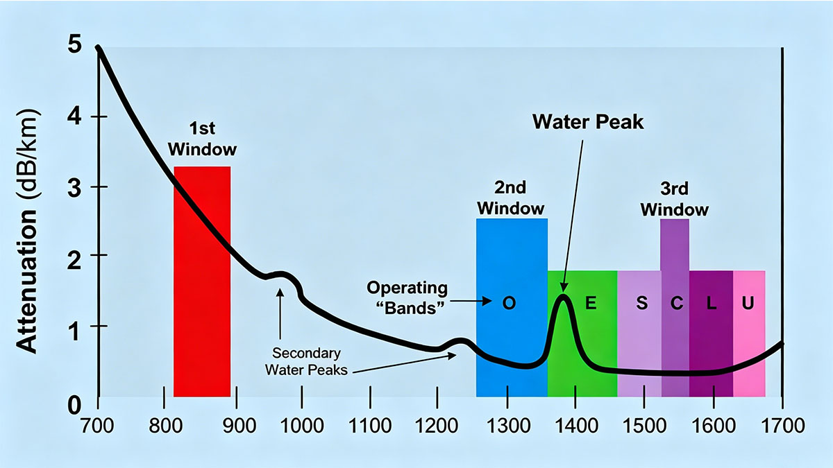
In practical deployments, attenuation is measured in decibels (dB) and is often expressed as loss per kilometer (dB/km). Lower attenuation values indicate that a fiber can carry signals over longer distances with less degradation. Network designers use attenuation calculations to determine whether a signal can reach its destination without falling below the receiver's sensitivity threshold.
Several factors contribute to attenuation in fiber optic networks:
- Absorption of light energy within the fiber material
- Scattering caused by microscopic imperfections in the glass
- Bending losses resulting from improper cable routing
- Connector and splice losses at connection points
- Environmental influences such as stress, temperature changes, and contamination
Understanding attenuation is essential because even small losses accumulate over long transmission paths. A well-designed optical link must account for every source of attenuation to maintain stable and efficient data transmission.
Understanding Optical Signal Loss
Optical signal loss occurs when a portion of the transmitted light fails to reach the receiving device. As light propagates through a fiber, some of its energy is absorbed, scattered, reflected, or diverted away from the intended path. This process reduces the optical power available at the receiver and can ultimately affect communication performance.
The amount of signal loss depends on several network characteristics:
- Fiber type and manufacturing quality
- Operating wavelength
- Cable length
- Number of connectors and splices
- Installation conditions
The following table illustrates typical attenuation values for commonly used optical fiber wavelengths.
| Fiber Type | Operating Wavelength | Typical Attenuation |
|---|---|---|
| Multimode Fiber | 850nm | 2.5–3.5dB/km |
| Multimode Fiber | 1300nm | 0.8–1.5dB/km |
| Single-Mode Fiber | 1310nm | ~0.35dB/km |
| Single-Mode Fiber | 1550nm | ~0.20dB/km |
These values demonstrate why long-distance networks typically operate at 1310nm or 1550nm wavelengths, where attenuation is significantly lower than in shorter-wavelength multimode systems.
An optical signal does not disappear instantly; rather, it gradually weakens over distance. Effective network design focuses on minimizing this loss to ensure that sufficient optical power reaches the receiving equipment.
Why Attenuation Matters in Communication Systems
Attenuation matters because it determines how far and how effectively optical signals can travel. Excessive attenuation can prevent a receiver from accurately detecting incoming data, leading to performance degradation and reduced network stability.
From a network engineering perspective, attenuation influences several critical areas:
- Maximum transmission distance
- Optical link budget calculations
- Receiver sensitivity requirements
- Error rate performance
- Overall network reliability
When attenuation exceeds acceptable limits, organizations may encounter the following issues:
- Increased bit error rates (BER)
- Reduced throughput
- Intermittent connectivity
- Service interruptions
- Additional infrastructure requirements
For this reason, attenuation is considered a foundational parameter during fiber optic network planning. Engineers evaluate expected losses before deployment to ensure that optical links maintain adequate power margins under both normal and adverse operating conditions.
📡 Main Causes of Attenuation in Fiber Optics
The main causes of attenuation in fiber optics include material absorption, Rayleigh scattering, fiber bending, connector and splice losses, and environmental influences. Some attenuation mechanisms are inherent to the fiber itself and cannot be completely eliminated, while others result from installation practices, component quality, or operating conditions. Understanding these causes is essential for reducing optical power loss and improving overall network performance.
In modern fiber optic systems, attenuation is rarely caused by a single factor. Instead, total link loss is typically the cumulative effect of multiple attenuation sources acting along the transmission path.
Material Absorption Losses
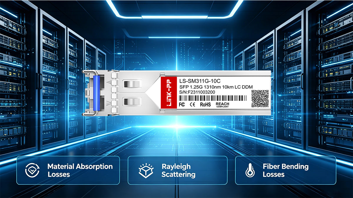
Material absorption occurs when portions of the optical signal are converted into heat within the fiber material. Although modern optical fibers are manufactured with extremely high-purity silica glass, a small amount of absorption remains unavoidable and contributes to overall attenuation.
Material absorption can be divided into two primary categories:
- Intrinsic absorption caused by the natural molecular structure of silica
- Extrinsic absorption caused by impurities introduced during manufacturing
- Residual hydroxyl (OH⁻) ions creating water peak absorption regions
- Trace metallic contaminants increasing signal loss
The impact of absorption varies depending on the operating wavelength. Fiber manufacturers continuously improve purification processes to minimize absorption and achieve lower attenuation levels across key transmission windows.
As transmission distances increase, even small absorption losses accumulate, making low-loss fiber materials particularly important for long-haul optical networks.
Rayleigh Scattering
Rayleigh scattering is the dominant source of attenuation in modern optical fibers. It occurs because microscopic density and refractive index variations within the glass scatter a portion of the transmitted light in different directions.
Several characteristics make Rayleigh scattering significant:
- It is an inherent property of optical fiber
- It cannot be completely eliminated
- It affects all fiber optic systems
- Its impact decreases at longer wavelengths
The primary factors influencing Rayleigh scattering include:
- Glass density fluctuations
- Molecular-scale structural irregularities
- Operating wavelength selection
- Fiber manufacturing quality
Because scattering loss is lower at longer wavelengths, many long-distance networks operate near 1550nm, where attenuation is significantly reduced compared to shorter wavelengths.
Fiber Bending Losses
Fiber bending losses occur when optical cables are bent beyond their recommended limits, causing part of the light signal to escape from the fiber core. Unlike intrinsic attenuation mechanisms, bending losses are often preventable through proper installation and cable management practices.
Fiber bending losses generally fall into two categories:
- Macrobending loss caused by large visible bends
- Microbending loss caused by small distortions within the fiber structure
Several installation-related issues can contribute to bending losses:
- Tight cable routing around corners
- Excessive cable tension
- Improper cable storage
- Overcrowded cable trays
- Mechanical pressure on fiber jackets
The table below highlights the differences between the two primary forms of bending loss.
| Bending Type | Primary Cause | Visibility | Impact on Signal |
|---|---|---|---|
| Macrobending | Large-radius bends | Easily visible | Moderate to severe |
| Microbending | Microscopic distortions | Usually invisible | Gradual signal degradation |
Maintaining proper bend radius specifications during installation is one of the most effective ways to minimize avoidable attenuation in fiber optic networks.
Connector and Splice Losses
Every connector and splice introduces a certain amount of insertion loss into a fiber link. While individual losses are often small, multiple connection points can significantly increase total attenuation across long network paths.
Connector and splice losses commonly result from:
- Core misalignment
- End-face contamination
- Air gaps between fiber ends
- Poor polishing quality
- Mechanical stress at connection points
Typical attenuation contributors include:
- Connector insertion loss
- Fusion splice loss
- Mechanical splice loss
- Reflectance-related losses
The quality of installation and maintenance directly affects the magnitude of these losses. Clean connectors, accurate alignment, and precision fusion splicing help maintain low attenuation levels throughout the network.
Because connector-related problems are among the most common causes of excessive optical loss, routine inspection and cleaning remain critical maintenance practices.
Environmental Factors
Environmental conditions can increase attenuation over time by affecting the physical condition and optical characteristics of fiber cables. While modern fibers are designed to withstand demanding operating environments, prolonged exposure to adverse conditions may still impact performance.
Key environmental factors include:
- Temperature fluctuations
- Mechanical vibration
- Moisture exposure
- Cable aging
- External pressure and stress
These conditions can contribute to:
- Increased microbending
- Material degradation
- Connector contamination
- Changes in optical characteristics
- Accelerated component wear
The severity of environmental attenuation depends on cable design, installation quality, and deployment location. Outdoor telecommunications networks, industrial facilities, and harsh-environment installations typically require additional protection measures to maintain stable optical performance.
📡 Attenuation Characteristics Across Different Fiber Types
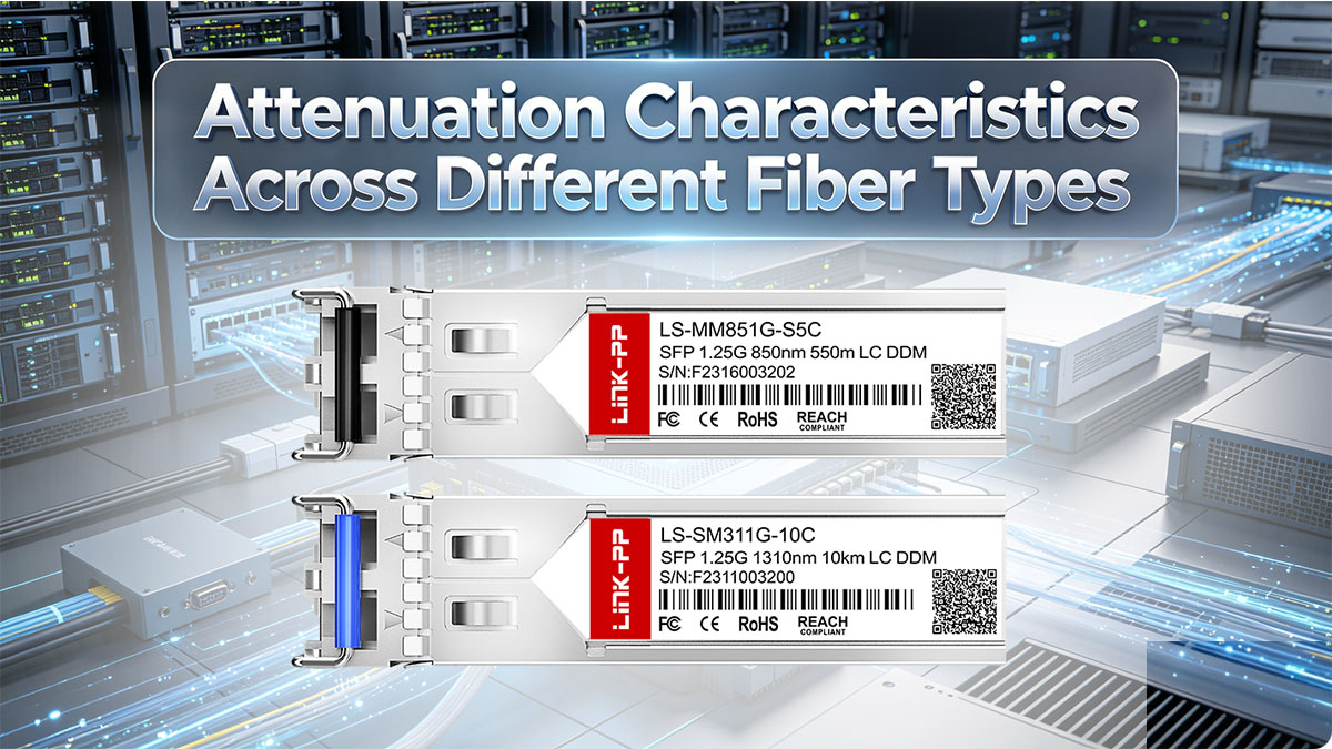
Attenuation characteristics vary significantly depending on fiber type and operating wavelength. Single-mode fiber generally exhibits lower attenuation than multimode fiber, making it the preferred choice for long-distance communication. In addition, attenuation changes across different wavelength windows, directly influencing transmission reach, network design, and optical system efficiency.
When evaluating fiber optic performance, it is important to consider both the physical structure of the fiber and the wavelength at which the network operates. These factors work together to determine overall signal loss and link reliability.
Single-Mode Fiber Attenuation
Single-mode fiber (SMF) offers the lowest attenuation among commonly deployed optical fibers. Its small core diameter allows light to travel through a single propagation mode, minimizing scattering effects and reducing overall signal degradation.
The primary attenuation characteristics of single-mode fiber include:
- Low optical loss over long distances
- Excellent performance in metropolitan and long-haul networks
- Support for high-speed transmission rates
- Compatibility with optical amplification technologies
The table below illustrates typical attenuation values for common single-mode operating wavelengths.
| Fiber Type | Operating Wavelength | Typical Attenuation |
|---|---|---|
| Single-Mode Fiber | 1310nm | Approximately 0.35dB/km |
| Single-Mode Fiber | 1550nm | Approximately 0.20dB/km |
| Single-Mode Fiber | 1625nm | Approximately 0.25–0.30dB/km |
These low attenuation levels enable transmission over tens or even hundreds of kilometers when combined with appropriate network design and signal amplification techniques.
Multimode Fiber Attenuation
Multimode fiber (MMF) typically experiences higher attenuation than single-mode fiber due to its larger core diameter and different operating wavelengths. While multimode systems are highly effective for shorter-distance applications, signal loss increases more rapidly over extended links.
Several characteristics define multimode attenuation performance:
- Higher attenuation compared to single-mode fiber
- Operation primarily at 850nm and 1300nm wavelengths
- Optimized for short- and medium-distance communication
- Common deployment in enterprise and data center environments
The following table summarizes typical multimode attenuation values.
| Fiber Type | Operating Wavelength | Typical Attenuation |
| Multimode Fiber | 850nm | 2.5–3.5dB/km |
| Multimode Fiber | 1300nm | 0.8–1.5dB/km |
The significant difference between 850nm and 1300nm attenuation demonstrates how wavelength selection can influence overall optical performance, even within the same fiber type.
Comparing Fiber Attenuation by Wavelength
Wavelength selection plays a crucial role in determining attenuation levels. Even when using the same fiber type, optical signals experience different amounts of loss depending on the transmission window being utilized.
The most commonly used wavelength windows include:
- 850nm
- 1300nm
- 1310nm
- 1550nm
- 1625nm
The table below compares typical attenuation performance across these wavelengths.
| Wavelength | Common Fiber Type | Typical Attenuation Range |
| 850nm | Multimode | 2.5–3.5dB/km |
| 1300nm | Multimode | 0.8–1.5dB/km |
| 1310nm | Single-Mode | ~0.35dB/km |
| 1550nm | Single-Mode | ~0.20dB/km |
| 1625nm | Single-Mode | ~0.25–0.30dB/km |
Among these transmission windows, 1550nm typically delivers the lowest attenuation and is therefore widely used in long-distance telecommunications networks. The reduced signal loss at this wavelength allows operators to extend transmission reach while minimizing the need for additional amplification or regeneration equipment.
However, wavelength selection is not based solely on attenuation. Network designers must also consider factors such as dispersion, equipment compatibility, regulatory requirements, and application-specific performance objectives.
📡 How Attenuation Is Measured in Fiber Networks
Attenuation measurement in fiber networks is the process of quantifying optical power loss between a transmitter and receiver. It is essential for verifying link quality, ensuring compliance with design specifications, and identifying hidden faults in fiber optic infrastructure. Accurate measurement allows engineers to confirm whether a fiber link can support the required transmission distance and data rate without signal degradation.
Optical Power Meter Testing
Optical power meter testing is one of the most direct and widely used methods for measuring attenuation in fiber networks. It compares the transmitted optical power with the received power to determine total link loss.
The fundamental principle of this method is straightforward: any reduction in measured optical power indicates attenuation along the fiber path. Engineers typically perform this test using a calibrated light source and a power meter placed at opposite ends of the fiber link.
The key characteristics of optical power meter testing include:
- Direct measurement of end-to-end insertion loss
- High accuracy for installed fiber links
- Fast and practical field deployment
- Dependence on proper calibration and reference setup
Before presenting structured measurement parameters, it is important to understand how different test configurations influence accuracy and reliability.
| Test Method | Measurement Focus | Typical Application |
|---|---|---|
| Light Source + Power Meter | Total link loss | Field commissioning |
| Loopback Testing | Bidirectional loss validation | Data center links |
| Reference Cable Method | Baseline calibration | Laboratory and field testing |
These measurement approaches allow technicians to validate whether total attenuation remains within the acceptable link budget defined during network design. After completing the test, results are compared against expected loss values to confirm system performance or identify excessive attenuation.
Proper setup is critical because inaccurate referencing or dirty connectors can lead to misleading results. Therefore, technicians must ensure that all optical interfaces are clean and correctly aligned before measurement begins.
Optical Time Domain Reflectometer (OTDR)
The Optical Time Domain Reflectometer (OTDR) is a more advanced tool used to analyze attenuation along the entire length of a fiber link. Unlike power meters, which measure total loss, OTDR provides a detailed loss profile by detecting reflections and backscattered light.
The OTDR works by sending short optical pulses into the fiber and analyzing the returned signal. This allows engineers to locate specific points of loss, including splices, connectors, bends, and breaks.
Key advantages of OTDR-based measurement include:
- Identification of loss events along the fiber span
- Distance-based fault localization
- Detection of microbends and macro-bends
- Visualization of overall fiber health
Before examining measurement parameters, it is important to understand how OTDR traces represent attenuation behavior across the link.
| OTDR Feature | Function | Diagnostic Value |
| Backscatter Trace | Displays signal decay over distance | Overall attenuation profile |
| Event Markers | Identifies connectors and splices | Localized loss detection |
| Reflectance Peaks | Highlights reflections | Connector quality assessment |
| Dead Zones | Indicates measurement blind spots | Limitation awareness |
These features make OTDR an indispensable tool for diagnosing complex fiber networks, especially in long-haul and metropolitan infrastructures. By interpreting trace patterns, engineers can determine whether attenuation is caused by fiber degradation, poor splicing, or installation errors.
Link Budget Analysis
Link budget analysis is a predictive method used during fiber network design to estimate whether the optical signal will remain above the receiver sensitivity threshold after accounting for all attenuation sources.
This method calculates total expected loss by summing all contributing factors in the transmission path. It is used to ensure that sufficient optical power margin exists for reliable operation under real-world conditions.
Typical components included in link budget calculations are:
- Fiber attenuation per kilometer
- Connector insertion loss
- Splice loss
- System margin for aging and environmental variations
- Equipment-specific losses
Before presenting the calculation structure, it is important to understand how each element contributes to total system loss.
| Loss Component | Typical Value Range | Impact on Link |
| Fiber Loss | 0.2–3.5dB/km | Distance-dependent attenuation |
| Connector Loss | 0.2–0.75dB each | Interface-related loss |
| Splice Loss | 0.05–0.3dB each | Joint-related loss |
| System Margin | 3–10dB | Safety and aging allowance |
These values help engineers determine whether a proposed fiber link design is feasible before physical deployment. If total calculated loss exceeds allowable limits, adjustments such as adding optical amplification or reducing link distance must be considered.
Link budget analysis ensures that attenuation is managed proactively rather than reactively, reducing the likelihood of service degradation after installation.
📡 Effects of Excessive Attenuation on Network Performance
Excessive attenuation in fiber optic networks leads to a significant reduction in received optical power, which directly impacts signal integrity and overall communication reliability. When the optical signal falls below the receiver sensitivity threshold, the system can no longer correctly interpret transmitted data, resulting in degraded performance or complete link failure. In modern high-speed networks, even small increases in attenuation can have noticeable operational consequences.
Reduced Transmission Distance
Excessive attenuation primarily reduces the effective transmission distance of a fiber optic link. As signal power decreases along the fiber, the maximum achievable span before signal regeneration or amplification is required becomes shorter.
The impact of attenuation on transmission distance can be summarized as follows:
- Higher attenuation reduces usable link length
- Additional amplification or regeneration may be required
- Network topology must be redesigned in some cases
- Long-haul performance becomes more limited
Before presenting structured effects, it is important to understand how distance constraints translate into real-world network limitations.
- Reduced reach between switches, routers, or optical transport equipment
- Increased reliance on intermediate optical devices
- Higher infrastructure complexity for wide-area networks
- Reduced design flexibility for future expansion
These limitations make attenuation control a critical factor in backbone and metropolitan network planning. Once transmission distance is compromised, network redesign or additional optical equipment is often required to restore performance levels.
Increased Bit Error Rates
Excessive attenuation has a direct impact on bit error rate (BER), which measures the number of incorrect bits received compared to total transmitted bits. As signal strength weakens, the receiver has more difficulty distinguishing between logical 0s and 1s, leading to higher error probability.
The relationship between attenuation and bit errors can be summarized through several key effects:
- Reduced signal-to-noise ratio (SNR)
- Increased susceptibility to electrical and optical noise
- Degradation of receiver decision accuracy
- Higher probability of corrupted data frames
Before listing specific performance consequences, it is important to recognize how sensitive modern optical systems are to power variations.
- Marginal signals become unstable under load
- Error correction mechanisms become heavily utilized
- Retransmissions increase network overhead
- Latency may rise due to repeated data recovery attempts
These effects are particularly critical in high-speed systems such as 10G, 40G, 100G, and higher-rate networks, where even minor optical degradation can significantly impact data integrity.
Service Reliability Issues
Excessive attenuation also affects overall service reliability, leading to unstable or intermittent network behavior. Unlike complete link failures, reliability issues often manifest as sporadic performance degradation that is more difficult to diagnose.
Common reliability problems caused by high attenuation include:
- Intermittent connectivity loss
- Packet drops during peak traffic periods
- Unexpected link flapping
- Reduced quality of service (QoS) stability
Before outlining specific reliability impacts, it is important to understand how attenuation-related instability develops in real environments.
- Marginal optical power levels fluctuate with temperature changes
- Connector contamination introduces variable losses
- Mechanical stress causes intermittent microbending effects
- Aging components gradually reduce signal margin
These factors combine to create unstable operating conditions, especially in environments where fiber infrastructure is exposed to vibration, temperature variation, or physical movement. Over time, such instability can significantly affect application performance and user experience.
Impact on High-Speed Optical Systems
High-speed optical systems are more sensitive to attenuation because they operate with tighter power budgets and higher modulation complexity. As data rates increase, the tolerance for signal degradation decreases, making attenuation control even more critical.
The impact of excessive attenuation on high-speed networks includes:
- Reduced margin for error correction
- Increased dependency on precise optical alignment
- Greater sensitivity to connector and splice quality
- Higher risk of link degradation at long distances
Before presenting structured observations, it is important to understand how different speed classes respond to attenuation.
| Data Rate | Sensitivity to Attenuation | Typical Impact |
|---|---|---|
| 10G | Moderate | Occasional performance degradation |
| 25G | High | Reduced link margin |
| 40G | High | Increased BER sensitivity |
| 100G+ | Very High | Strict power budget requirements |
These characteristics show that as transmission speed increases, allowable attenuation margins become tighter. In high-speed data center interconnects and carrier-grade networks, even small losses in optical power can significantly affect system stability.
As a result, managing attenuation is not only important for maintaining current performance but also for ensuring scalability in future high-capacity optical infrastructures.
📡 Signal Recovery Strategies for Fiber Optic Attenuation
Signal recovery strategies in fiber optic networks focus on restoring or maintaining sufficient optical power when attenuation reduces signal strength below acceptable operating levels. These strategies are essential for ensuring stable transmission, especially in long-distance, high-speed, or high-density network environments where cumulative losses are unavoidable.
Optimizing Fiber Installation Practices
Proper installation practices are one of the most effective ways to prevent unnecessary signal loss. Many attenuation issues originate from physical stress or improper handling during deployment, making installation quality a key factor in long-term network performance.
Effective installation optimization includes:
- Maintaining recommended bend radius limits
- Avoiding excessive pulling tension during cable routing
- Ensuring proper cable support in trays and conduits
- Preventing microbending caused by mechanical pressure points
- Following structured fiber management guidelines
Before listing structured installation considerations, it is important to understand how small physical deviations can significantly affect optical performance over long distances.
- Even minor bends can introduce measurable signal loss
- Repeated stress can degrade fiber integrity over time
- Poor routing increases cumulative attenuation across the link
- Mechanical instability can cause intermittent performance issues
These factors highlight why installation quality directly influences attenuation levels. By controlling physical conditions during deployment, many avoidable losses can be eliminated at the source, reducing the need for later compensation mechanisms.
Improving Connector and Splice Quality
Connector and splice quality plays a major role in minimizing localized attenuation points within a fiber network. Each connection introduces potential loss, and poor workmanship or contamination can significantly increase overall signal degradation.
Key methods for improving connection quality include:
- Regular cleaning of connector end-faces using approved tools
- Using precision alignment connectors with tight tolerances
- Applying fusion splicing for low-loss permanent joints
- Inspecting connectors before every mating cycle
- Avoiding reuse of damaged or contaminated ferrules
Before presenting structured quality factors, it is important to recognize how connection-related losses accumulate in real deployments.
- Multiple connectors increase total insertion loss
- Dust or oil contamination can severely disrupt signal transmission
- Misalignment leads to reflection and scattering losses
- Poor splicing quality introduces permanent attenuation points
These issues are especially critical in dense fiber environments such as data centers, where large numbers of connections exist within short distances. Maintaining connector hygiene and splice accuracy is therefore essential for sustaining stable optical performance.
Using Optical Amplifiers
Optical amplifiers are widely used in fiber optic systems to restore signal strength without converting optical signals into electrical form. They amplify the optical signal directly, allowing networks to extend transmission distances while compensating for attenuation.
Common benefits of optical amplification include:
- Extension of long-haul transmission distances
- Reduction in need for electrical regeneration
- Support for high-capacity wavelength-division multiplexing systems
- Improved signal strength across multi-span networks
Before examining amplifier types, it is important to understand how amplification integrates into modern optical systems.
- Amplifiers are typically placed at strategic points in long-distance links
- They compensate for accumulated fiber attenuation
- They help maintain required receiver power levels
- They support scalable backbone network design
Two widely used optical amplification technologies are described below.
EDFA Technology
Erbium-Doped Fiber Amplifiers (EDFA) are the most commonly deployed optical amplifiers in long-distance communication systems, particularly in the 1550nm transmission window.
Key characteristics of EDFA include:
- High gain efficiency in C-band and L-band wavelengths
- Low noise figure compared to electrical regeneration
- Compatibility with dense wavelength-division multiplexing (DWDM)
- Mature and widely deployed technology in telecom networks
EDFA systems are especially effective in backbone and submarine cable systems where maintaining signal integrity over extremely long distances is required.
Raman Amplification
Raman amplification provides distributed optical gain by using the transmission fiber itself as the amplification medium. Unlike EDFAs, which amplify at discrete points, Raman amplification can extend signal strength along the fiber span.
Key advantages include:
- Distributed gain along the fiber length
- Improved noise performance in certain configurations
- Flexibility in wavelength optimization
- Enhanced performance in ultra-long-haul systems
Although more complex to implement, Raman amplification is valuable in high-performance optical networks requiring extended reach and improved signal-to-noise ratio control.
Deploying Optical Regeneration Systems
Optical regeneration systems restore signal quality by not only amplifying the optical power but also reshaping and retiming the signal. This process is different from simple amplification because it addresses both power loss and signal distortion.
Key functions of optical regeneration include:
- Signal reshaping to restore waveform integrity
- Retiming to correct synchronization errors
- Noise reduction through electrical conversion stages
- Restoration of degraded digital signals
Before outlining practical implications, it is important to understand how regeneration fits into long-distance networks.
- Used when amplification alone is insufficient
- Typically deployed in ultra-long-haul transmission systems
- Helps maintain signal integrity across multiple spans
- Ensures compatibility with high-speed transmission protocols
Regeneration is often applied in combination with optical amplification to maintain high-quality transmission over extremely long distances or highly complex network paths.
Selecting Low-Loss Fiber Components
Component selection plays a critical role in minimizing attenuation at the system level. Even when fiber installation is optimal, poor-quality components can introduce unnecessary signal loss.
Important considerations include:
- Low-loss fiber cables with optimized refractive index profiles
- High-precision connectors with minimal insertion loss
- Fusion-spliced joints with controlled attenuation characteristics
- Certified components compliant with industry standards
Before summarizing key selection principles, it is important to highlight how component quality affects long-term performance.
- High-quality components reduce cumulative attenuation
- Stable performance reduces maintenance requirements
- Improved optical alignment minimizes signal disruption
- Better materials increase network lifespan
By selecting appropriate components during the design and procurement phase, network operators can significantly reduce the need for later compensation and improve overall system reliability.
📡 Best Practices for Minimizing Attenuation in Fiber Optic Networks
Minimizing attenuation in fiber optic networks requires a combination of careful system design, disciplined installation practices, and ongoing maintenance. Since optical loss accumulates across fiber spans, connectors, and environmental interactions, even small inefficiencies can significantly impact total link performance. Effective mitigation strategies focus on reducing avoidable losses while maintaining stable long-term transmission quality.
Network Design Optimization
Proper network design is the foundation for minimizing attenuation because it defines how optical power is distributed across the entire link. A well-designed system ensures that signal strength remains within acceptable margins even after accounting for all expected losses.
Key design optimization practices include:
- Performing accurate link budget calculations before deployment
- Selecting appropriate fiber types based on distance and data rate requirements
- Minimizing the number of intermediate connection points
- Planning efficient physical routing paths to reduce total fiber length
- Incorporating safety margins for aging and environmental variation
Before listing structured design considerations, it is important to recognize how design decisions directly influence optical performance.
- Shorter routes reduce cumulative fiber loss
- Fewer connectors lower insertion loss accumulation
- Proper margin planning prevents future performance degradation
- Optimized architecture improves scalability and reliability
These principles ensure that attenuation is addressed at the architectural level, reducing dependence on corrective measures after deployment. A robust design phase significantly lowers the risk of exceeding allowable optical power budgets in operational networks.
Installation and Maintenance Guidelines
Installation quality has a direct and lasting impact on attenuation levels, as physical handling errors often introduce permanent or semi-permanent signal loss. Maintenance practices are equally important for preventing gradual performance degradation over time.
Key installation and maintenance practices include:
- Following manufacturer-specified bend radius requirements
- Avoiding excessive pulling tension during cable installation
- Ensuring proper fiber routing in trays and conduits
- Cleaning connectors before every mating operation
- Performing regular inspection of splices and termination points
Before outlining detailed operational impacts, it is important to understand how physical handling affects attenuation behavior.
- Improper bending introduces microbending losses
- Contaminated connectors increase insertion loss
- Loose or damaged splices create permanent loss points
- Mechanical stress accelerates fiber degradation
These factors highlight that many attenuation issues originate from preventable installation errors. Consistent adherence to standardized procedures helps ensure stable optical performance and reduces long-term maintenance costs.
Continuous Performance Monitoring
Continuous performance monitoring allows network operators to detect early signs of attenuation-related issues before they develop into service disruptions. By tracking optical power levels and analyzing link behavior over time, potential problems can be identified and resolved proactively.
Effective monitoring practices include:
- Real-time optical power level tracking
- Periodic OTDR testing for fault localization
- Threshold-based alerting for signal degradation
- Historical performance trend analysis
- Predictive maintenance based on attenuation patterns
Before presenting structured monitoring benefits, it is important to understand how early detection improves network resilience.
- Small losses can be corrected before impacting service quality
- Faults can be isolated without full network downtime
- Maintenance scheduling becomes more efficient
- Long-term degradation patterns can be identified
These advantages make continuous monitoring a critical component of modern fiber optic network management. Instead of reacting to failures, operators can maintain system stability through proactive intervention.
📡 Conclusion
Attenuation in fiber optics refers to the gradual loss of optical signal power as it travels through a fiber cable, and it remains one of the most critical performance factors in modern optical communication systems. Understanding fiber optic attenuation and signal loss mechanisms is essential for designing reliable, high-speed networks that maintain stable transmission over varying distances and conditions.
Across different fiber types, wavelengths, and network architectures, attenuation directly influences transmission reach, signal integrity, and overall system efficiency. Effective management of optical attenuation ensures that communication links remain within their power budgets and continue to deliver consistent performance in both short-range and long-haul applications.
The most important insights from this guide can be summarized as follows:
- Attenuation in fiber optics is caused by absorption, scattering, bending, connectors, and environmental factors
- Single-mode fiber typically provides lower attenuation than multimode fiber, especially at 1550nm
- Accurate measurement using optical power meters and OTDR is essential for diagnosing signal loss
- Excessive attenuation leads to reduced transmission distance, higher bit error rates, and unstable network performance
- Signal recovery strategies such as proper installation, amplification, and high-quality components are critical for maintaining link integrity
These points highlight that attenuation management is not a single corrective action but a continuous engineering practice spanning design, deployment, and maintenance.
Maintaining low attenuation is fundamental to achieving stable, high-performance optical networks. By applying proper design principles, selecting high-quality fiber components, and implementing effective monitoring strategies, organizations can significantly improve long-term network reliability and scalability.
For professionals seeking to optimize fiber optic performance and reduce signal loss in real-world deployments, exploring high-quality optical components and connectivity solutions can further enhance system stability. The LINK-PP Official Store provides a wide range of fiber optic modules and interconnect solutions designed to support efficient, low-loss optical communication infrastructure, helping networks maintain strong performance across demanding environments.







