شحن مجاني يزيد عن 600 دولار، إذا كنت بحاجة إلى سعر أفضل، فيرجى الاتصال بنا مباشرة.
هل تحتاج إلى مساعدة؟
الدردشة الحية معنا
دردشة مباشرة
تريد الاتصال بنا؟

+ 86-752-3386717

Language: English
  1. English
  2. Русский
  3. Português
  4. Español
  5. Nederlands
  6. Français
  7. Italiano
  8. Deutsch
  9. العربية
  10. Ελληνικά
  11. にほんご
  12. 한국어
  13. Tiếng Việt
  14. Indonesian
  15. Thai
Currency: USD
USD - US Dollar
EUR - Euro
GBP - British Pound
CAD - Canadian Dollar
AUD - Australian Dollar
JPY - Japanese Yen
SEK - Swedish Krona
NOK - Norwegian Krone
IDR - Indonesia Rupiahs
BRL - Brazilian Real
THB - Thailand Baht
  • اهتم بشؤونك من خلال مجموعة متنوعة من خيارات الدفع الموثوقة.

  • استخدم رقم الطلب أو رقم التتبع للتحقق من حالة الشحن.

  • احصل على عرض الأسعار الخاص بك بسرعة ونقدم لك خدمة أكثر احترافية.

  • ساعد في إدارة ميزانيتك ونفقاتك بشكل أفضل.

  • قابلنا وتعرف على مهمتنا وإيماننا وخدمتنا والمزيد.

  • ابحث عن مواقعنا وتواصل معنا عن كثب.

  • اكتشف مدى اهتمامنا بالجودة.

  • معرفة آخر الأخبار والأحداث حولها l-p.com

  • دراسة متعمقة للأدلة التقنية ومعايير الصناعة ومعلومات التوافق مع وحدات SFP.

  • معايير تفصيلية للمنتجات ومقارنات جنبًا إلى جنب لمساعدتك في اختيار الوحدة المناسبة.

  • استكشف حلول الاتصال الواقعية لمراكز البيانات والمؤسسات وشبكات الاتصالات.

  • نصائح أساسية حول اختيار معدلات نقل البيانات، ومسافات الإرسال، وأنواع الموصلات.

اللغة
  1. الإنجليزية
  2. Русский
  3. البرتغالية
  4. الإسباني
  5. français
  6. إيطالية
  7. Deutsch
  8. العربية
  9. に ほ ん ご
  10. تينغ نام
  11. الأندونيسية
  12. تايلاندي
اختر العملة
USD - الدولار الأمريكي
يورو - يورو
GBP - الجنيه البريطاني
CAD - الدولار الكندي
AUD - الدولار الاسترالي
الين الياباني JPY - الين الياباني
SEK - كرونا سويدية
NOK - كرونة نرويجية
IDR - الروبية الاندونيسية
BRL - ريال برازيلي
THB - باهت تايلاندي
مدونة او مذكرة / SFP Electrical Connector Types and Signal Comparison Guide

SFP Electrical Connector Types and Signal Comparison Guide

26 أيار 2026 LINK-PP-مرح مركز المعرفة

SFP Electrical Connector Types and Signal Comparison Guide

The SFP electrical connector is the host-side 20-contact, 0.8 mm card-edge interface that mates with an SFP-family module through the cage. It carries high-speed differential data, low-speed control lines, power, and management signals. In SFP+ hosts, the low-speed interface is based on 3.3 V LVTTL, and the high-speed path is built around 100 Ω differential signaling.

:contentReference[oaicite:0]{index=0}

Although many engineers use the term “SFP connector” loosely, the host-side receptacle is defined as part of a 0.8 mm card-edge connector system. SNIA separates the connector, cage, and module into different specifications, and newer pluggable generations such as SFP28, SFP56, and SFP112 extend that same family while relying on higher-level standards such as IEEE or FC-PI for performance requirements.

:contentReference[oaicite:1]{index=1}

In practice, this means the connector choice is not just a mechanical decision. It affects signal integrity, EMI behavior, grounding strategy, insertion force, and PCB footprint constraints. For that reason, a correct comparison of SFP, SFP+, and later-generation interfaces must look at both electrical signaling and mechanical implementation.

This guide explains the following:

  • what an SFP electrical connector is and where it sits in the port stack
  • how SFP, SFP+, and SFP28 differ at the signal level
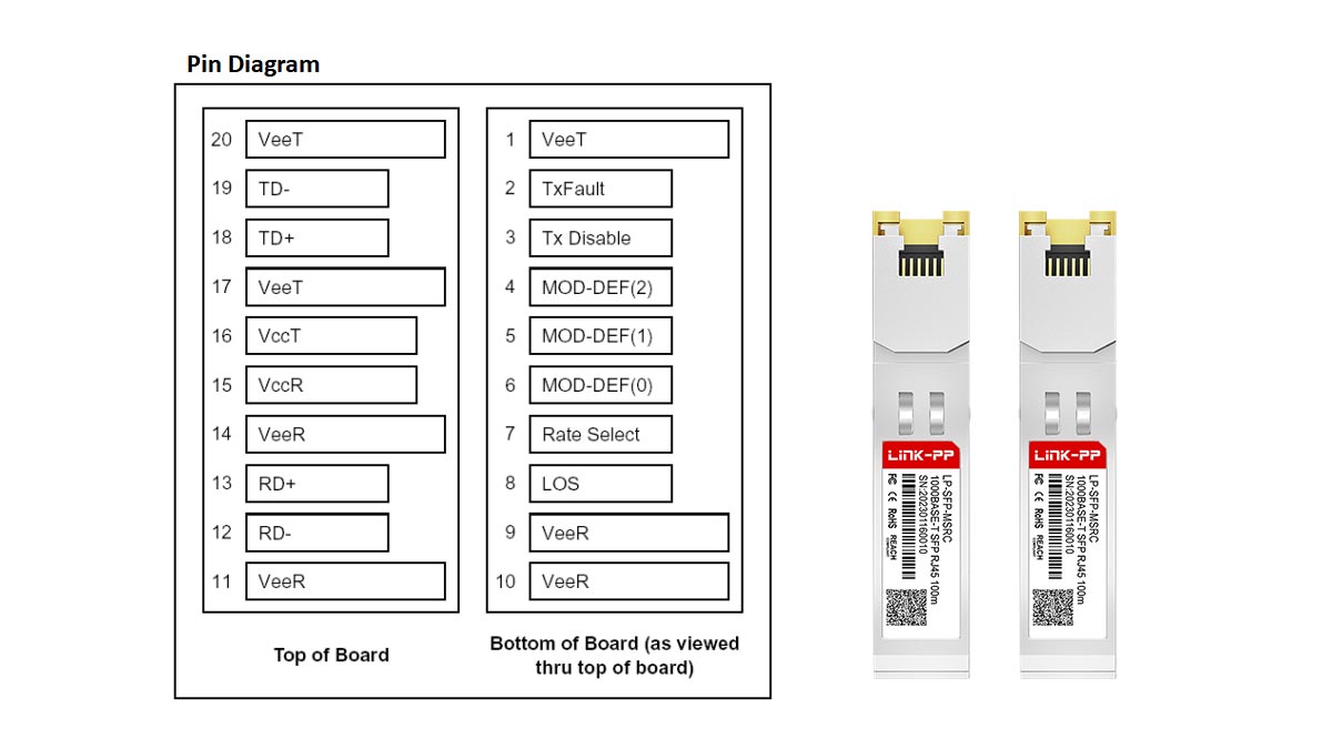
  • which pins carry data, power, control, and management functions
  • how the connector relates to the cage and the module
  • what matters most for PCB layout, grounding, and EMI control

⏩ What Is an SFP Electrical Connector?

An SFP electrical connector is the PCB-mounted host receptacle that provides the electrical interface between an SFP-family transceiver module and the host device. It is installed beneath the SFP cage and mates with the module’s 20-position card-edge contact interface. The connector carries high-speed transmit and receive signals, power, grounding, and management signals required for module identification, diagnostics, and network communication.

What Is an SFP Electrical Connector?

In a typical Ethernet switch, router, server, or industrial networking device, an SFP port consists of three separate components working together:

  1. وحدة SFP – The removable optical or copper transceiver.
  2. قفص SFP – The metal enclosure that provides mechanical retention and EMI shielding.
  3. SFP Electrical Connector – The host-side connector that transfers electrical signals between the module and the PCB.

Many engineers and buyers mistakenly use the term "SFP connector" to describe the entire port. In reality, the connector is only one part of the complete assembly. Understanding this distinction is important when designing hardware, sourcing components, or troubleshooting connectivity issues.

The Physical Location of the SFP Electrical Connector

The SFP electrical connector is mounted directly on the host PCB and positioned inside the SFP cage. When a transceiver module is inserted into the port, its gold-plated edge contacts slide into the connector and establish electrical continuity with the host system.

The signal path can be simplified as follows:

Fiber Cable

SFP Module

SFP Electrical Connector

PCB

Switch ASIC / NIC / FPGA

Unlike the cage, which primarily serves a mechanical and shielding function, the connector is responsible for carrying all electrical communication between the host and the transceiver.

What Signals Pass Through an SFP Electrical Connector?

An SFP electrical connector supports both high-speed data transmission and low-speed management functions.

فئة الإشارة الوظيفة
TX± Differential Pair Host transmits data to module
RX± Differential Pair Module transmits data to host
Power (VccT/VccR) Supplies operating voltage
أرض Electrical reference and shielding
SDA / SCL I²C serial communication
TX تعطيل Turns off optical transmitter
خطأ TX Reports transmitter faults
فقدان الإشارة (LOS) Indicates received signal failure

These signals enable modern networking equipment to support hot-swapping, digital diagnostics monitoring (DDM/DOM), module identification, and real-time link management.

SFP Electrical Connector vs. SFP Cage vs. SFP Module

One of the most common sources of confusion is the relationship between the connector, cage, and transceiver. The table below highlights their different functions.

مكون الوظيفة الأساسية التوصيلات الكهربائية قابل للإزالة
وحدة SFP Optical or copper transceiver نعم نعم
قفص SFP Mechanical retention and EMI shielding لا لا
SFP Electrical Connector Electrical interface to PCB نعم لا

مفتاح الوجبات الجاهزة: The module converts network signals, the cage secures and shields the module, and the electrical connector serves as the bridge that carries signals between the module and the host PCB.

Why the SFP Electrical Connector Matters

At Gigabit Ethernet speeds, connector performance has a measurable effect on system reliability. At 10G, 25G, and higher data rates, connector quality becomes even more critical because the connector directly influences:

  • سلامة الإشارة
  • Differential impedance control
  • فقدان الإدراج
  • عودة الخسارة
  • التداخل الكهرومغناطيسي (EMI)
  • Electrostatic discharge (ESD) performance
  • Long-term mating durability

A poorly designed connector can introduce reflections, crosstalk, and excessive attenuation that degrade link performance even when the transceiver module itself meets specification.

Engineering Insight:

When selecting an SFP electrical connector, engineers should evaluate more than mechanical compatibility. The most successful high-speed designs consider connector impedance, grounding strategy, cage integration, PCB stack-up, and compliance with relevant SFP Multi-Source Agreement (MSA) specifications. In modern 10G and 25G platforms, signal integrity issues are often traced back to connector and PCB layout decisions rather than the optical module itself.

In short, an SFP electrical connector is the host-side electrical interface at the heart of every SFP port. It connects the removable transceiver module to the system PCB, enabling power delivery, data transmission, diagnostics, and network communication while working alongside the SFP cage to form a complete pluggable interface.


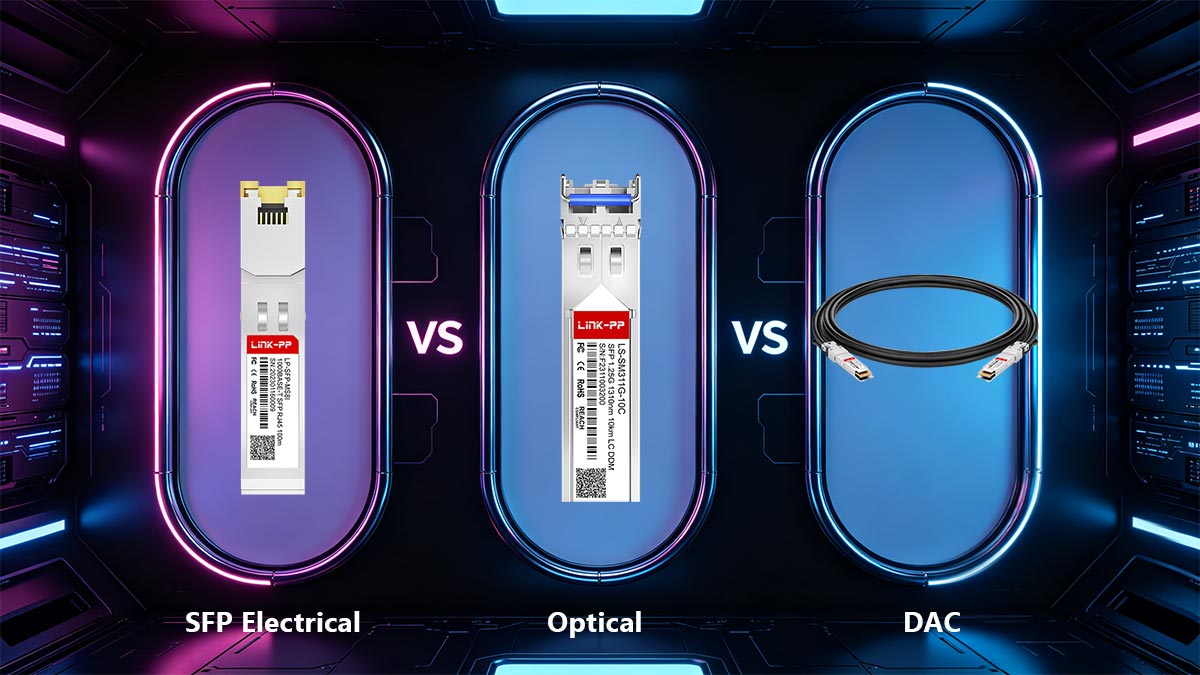
⏩ SFP Electrical vs. Optical vs. DAC: A Technical Comparison

SFP-based connectivity can be implemented through three primary approaches: electrical Ethernet transceivers (RJ45), Direct Attach Copper (DAC) cables, and fiber optic transceivers. Each technology addresses a different balance of transmission distance, power consumption, latency, deployment cost, and scalability. For short-range rack-level networking, DAC is typically the most cost-effective solution. For structured copper cabling infrastructure, RJ45-based SFP modules provide flexibility. For long-distance, high-bandwidth, and EMI-sensitive environments, fiber optic SFP modules remain the preferred choice.

SFP Electrical vs. Optical vs. DAC: A Technical Comparison

When selecting an SFP connectivity solution, engineers should evaluate not only transmission speed but also cabling architecture, switch density, power budget, future scalability, and environmental conditions.

SFP Connectivity Technology Comparison

معامل Electrical SFP (RJ45) كابل DAC SFP بصري
وسيط نقل Twisted Pair Copper تويناكس النحاس الألياف البصرية
موصل نموذجي RJ45 Integrated Twinax Assembly LC دوبلكس
المسافة النموذجية حتى 100 م 0.5–7 m (Passive)
Up to 15 m (Active)
مئات الأمتار إلى عشرات الكيلومترات
كمون منخفض أدنى منخفض
استهلاك الطاقة متوسط إلى مرتفع أدنى منخفض إلى متوسط
قابلية التداخل الكهرومغناطيسي أكثر معتدل المناعي
مرونة التثبيت أسعار محدودة بطول الكابل أسعار
تكلفة الكابل منخفض منخفظ جدا معتدل
تكلفة جهاز الإرسال والاستقبال معتدل None (integrated) متوسط ​​إلى مرتفع
استخدام مركز البيانات طبقة الوصول أعلى الرف (ToR) Spine-Leaf, Inter-Building
التوسعة معتدل محدود أسعار
 

When to Choose Electrical SFP (RJ45) Connections

Choose RJ45 SFP when you need to connect to existing Cat5e/Cat6/Cat6A infrastructure and want a simple copper upgrade path. It is a practical option for enterprise access networks, branch offices, and industrial Ethernet deployments.

وتشمل التطبيقات النموذجية:

  • مفاتيح الوصول الخاصة بالمؤسسة
  • شبكات إيثرنت الصناعية
  • Branch office deployments
  • بناء أنظمة التشغيل الآلي
  • Legacy copper-based infrastructure

When to Switch to Direct Attach Copper (DAC) Cables

Choose DAC for short-distance links inside the same rack or between adjacent racks. It offers low latency, low power consumption, and very low cost, making it ideal for data centers and high-density server environments.

A DAC cable typically consists of:

  • كابل نحاسي تويناكس
  • Integrated SFP+, SFP28, or QSFP connectors
  • Factory-calibrated signal path

This architecture minimizes insertion loss and reduces component count.

When Fiber Optic SFP Modules Are the Better Choice

Choose fiber when you need longer distance, better signal integrity, or immunity to EMI. Fiber SFP modules are the preferred solution for spine-leaf networks, campus links, telecom environments, and other high-performance or high-interference deployments.

Common Fiber SFP Categories

نوع الوحدة النمطية نوع الألياف المسافة النموذجية
1000BASE-SX الألياف المتعدد حتى 550 م
1000BASE-LX الألياف أحادية الوضع يصل إلى 10 كم
10 جرام SFP + SR الألياف المتعدد يصل إلى 300-400 متر
10 جرام SFP + LR الألياف أحادية الوضع يصل إلى 10 كم
25G SFP28 SR الألياف المتعدد حتى 100 م
25G SFP28 LR الألياف أحادية الوضع يصل إلى 10 كم

أفضل حالات الاستخدام

Fiber optic SFP modules are generally the preferred solution for:

  • شبكات الحرم الجامعي
  • بنية مراكز البيانات ذات العمود الفقري والورقة
  • Metropolitan Ethernet networks
  • البنية التحتية للاتصالات
  • Industrial facilities with high EMI exposure
  • Future-proof network upgrades

التوصية النهائية

  • منفذ RJ45 SFP for existing copper networks
  • DAC for short, low-cost rack-to-rack links
  • الألياف SFP for long-distance, scalable, EMI-safe connectivity

⏩ SFP Electrical Signals and Pin Functions

An SFP electrical connector carries two high-speed differential data pairs, 3.3 V power, ground, and a small set of low-speed control and management signals. In the SFP+ family, the high-speed path is designed around low-voltage AC-coupled signaling with nominal 100 Ω differential impedance, while the low-speed side handles module control, status, and I²C management.

SFP Electrical Signals and Pin Functions

1) TX/RX differential pairs

The transmit and receive pairs are the core data paths. TX carries host-to-module traffic, and RX carries module-to-host traffic. These are differential signals, which helps preserve signal integrity at high speed and reduce noise sensitivity across the connector interface.

2) Power and ground

The host provides two 3.3 V power rails: VccT for the transmitter side and VccR for the receiver side. The specification also states that each connector contact can carry up to 500 mA continuous and peak current, and that during hot-plug insertion the ground, voltage, and signal contacts mate in a defined order.

3) I²C management interface

SCL is the serial clock line, and SDA is the bidirectional serial data line used for module management and identification. The host pulls both lines up through resistors, and the module operates as a slave device on the 2-wire interface.

4) Rx_LOS

Rx_LOS means receiver loss of signal. When asserted high, it indicates that the received optical signal has dropped below the level defined by the relevant standard. It is an open-drain/open-collector output, and in some implementations it may be optional or reported only through the 2-wire interface.

5) TX_DISABLE

TX_DISABLE lets the host turn the transmitter off. In practice, it is used during initialization, shutdown, maintenance, or fault isolation. The SFP+ specification also defines timing behavior for how the module responds after TX_DISABLE is asserted or released.

6) TX_FAULT

TX_FAULT reports a transmitter-side fault condition. If the module detects a safety-related transmitter problem, it asserts TX_FAULT and the host can treat that as a fault indication if it remains asserted beyond the startup window.

خلاصة عملية: For design and troubleshooting, the easiest way to think about the connector is this: TX/RX move data, VccT/VccR power the module, ground provides return and reference, SCL/SDA manage the module, Rx_LOS reports receive failure, TX_DISABLE controls output, and TX_FAULT reports transmitter problems.


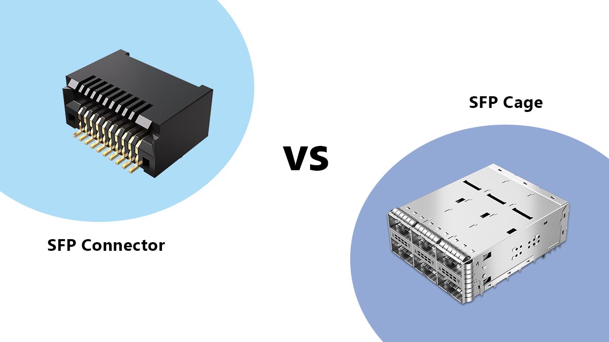
⏩ SFP Connector vs. SFP Cage: What’s the Difference?

The SFP electrical connector is the PCB-mounted contact interface that carries data, power, ground, and management signals between the host system and the module. The SFP cage is the metal structure that holds the module in place, provides the insertion opening, and helps with EMI control. In other words, the connector makes the electrical connection, while the cage provides the mechanical and shielding function.

مكون دور أساسي ماذا يفعل ما لا يفعله
SFP Electrical Connector واجهة كهربائية Mates with the module’s edge contacts and carries host-side signals Does not retain the module mechanically
قفص SFP Mechanical + shielding structure Guides insertion, supports retention, and helps limit EMI leakage Does not carry the signal path by itself

The distinction matters in hardware design. The SFP connector is part of the host board layout and sits underneath the cage assembly. The cage and connector are specified as a system in the SFP mechanical documentation, which is why proper port design must consider both fit and signal integrity.

SFP Connector vs. SFP Cage: What’s the Difference?

الاحتفاظ الميكانيكي

The cage is the part that gives the port its physical shape and keeps the module aligned during insertion and removal. It also works with the latch or pull tab on the module to provide retention. The connector alone cannot hold the module securely in place.

حماية EMI

The cage helps form the conductive enclosure around the module opening, which reduces EMI leakage and improves shielding continuity at the port. This is especially important at higher data rates, where the port must preserve signal quality while limiting radiation and susceptibility.

الاتصال الكهربائي

The connector is the only part that actually transfers the electrical interface from the module to the PCB. It carries the high-speed TX/RX paths, power rails, ground references, and low-speed management lines. Without the connector, the cage would be only a mechanical shell.

خلاصة عملية: when engineers say “SFP port,” they often mean the full cage-and-connector assembly. But for layout, sourcing, and troubleshooting, it helps to separate the roles: the cage holds and shields, the connector connects.


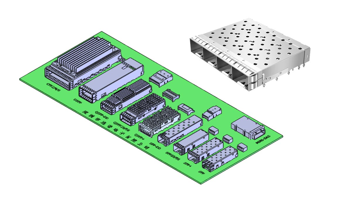
⏩ SFP Connector Footprint, Dimensions, and PCB Layout Basics

The SFP host connector is a right-angled, PCB-mounted card-edge receptacle that mates with the module’s paddle card inside the cage. The SFP family uses a 0.8 mm contact pitch, 20 contacts, and a sequenced mating order so ground connects first, then power, then signal contacts. The connector system is designed as part of the host board and cage assembly, not as a standalone part.

SFP Connector Footprint, Dimensions, and PCB Layout Basics

تصاعد النمط

In the SFP+ connector specification, the board-side connector is a 1 × 0.8 mm card-edge connector with a right-angled body receptacle. The host board footprint includes locator pegs and a defined pad pattern, with 0.80 mm contact pitch within each row, 0.40 mm row-to-row spacing, and a typical 9.60 mm peg-to-peg spacing.

Keep-out area

The module paddle card requires a minimum 5.50 mm component/solder mask keep-out area. The contact geometry also defines the start points for the ground and power pad regions, which helps prevent solder mask intrusion and preserves reliable edge contact during insertion.

Layout considerations for host boards

For a reliable SFP port, the host board should follow the specified contact sequencing: ground first, power second, signal last. The cage or latching structure is also required to guide the paddle card into the connector, provide sufficient wipe on the contacts, and create a hard stop so the module does not bottom out in the connector. The cage shield contact should make contact before the signal pins and break contact last to help reduce ESD and enclosure-to-enclosure potential differences.

Practical design summary: A correct SFP footprint is not just a pad pattern. It is a matched set of connector geometry, keep-out control, cage alignment, and contact sequencing. For PCB layout, the safest approach is to use the exact connector vendor footprint together with the SFF mechanical limits, then verify insertion depth, peg placement, and cage-to-board alignment before release.


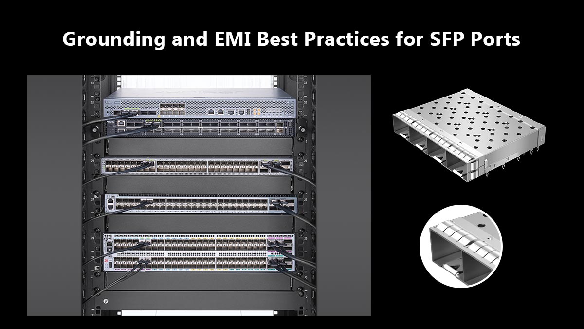
⏩ Grounding and EMI Best Practices for SFP Ports

The safest SFP grounding strategy is to treat the cage and shield as chassis ground, keep them separate from circuit ground, and use a low-impedance path to the enclosure. The SFP MSA explicitly says that chassis grounds and external EMI shields should not be attached to circuit ground, and it also recommends shutting off the connector signals when the transceiver is removed to improve EMI protection.

For high-speed designs, the port should use short, matched differential traces, proper Vcc and GND via stitching, and standard controlled-impedance routing practices. The SFP+ electrical specification recommends short and equal-length differential signal lines, microstrip routing where appropriate, and 50 Ω terminations on the host side.

Grounding and EMI Best Practices for SFP Ports

تأريض الدرع

The metal cage should provide a continuous shielding path around the module opening and connect to the chassis with a low-inductance bond. This helps contain radiated emissions and improves immunity to external noise. In practice, the shield should make reliable contact at the port opening and avoid relying on a long signal-ground return path for EMI control.

Chassis connection

Do لست tie the cage or external shield directly into noisy circuit ground. Instead, reference the shield to chassis or enclosure ground so high-frequency currents can return through the mechanical shell rather than through sensitive signal reference planes. This separation is a core EMC principle and is specifically called out in the SFP MSA.

Noise control for high-speed links

Keep the differential TX/RX pairs short, symmetric, and impedance-controlled, and place power decoupling close to the connector and host IC. The SFP+ specification also notes that the low-speed and power interfaces are part of the host-side electrical design, so layout quality directly affects link stability and EMI margin.

نصائح عملية

A well-designed SFP port follows three rules: ground the cage to chassis, isolate shield from circuit ground, and route the high-speed pairs with strict impedance control. When these three are done correctly, the port is far more likely to meet EMI targets and maintain stable high-speed operation.


⏩ FAQ About SFP Electrical Connector Types and Signals

FAQ About SFP Electrical Connector Types and Signals

1. Is an SFP electrical connector the same as an SFP cage?

No. The connector and cage serve different functions. The connector provides the electrical interface, while the cage provides mechanical retention, module guidance, and EMI shielding. A complete SFP port typically contains both components.

2. How many pins does an SFP connector have?

An SFP electrical connector uses a 20-contact interface based on a 0.8 mm card-edge design. These contacts support data transmission, power delivery, grounding, module management, and status monitoring.

3. What signals pass through an SFP electrical connector?

The connector carries:

  • TX± differential transmit signals
  • RX± differential receive signals
  • Vcc power rails
  • Ground references
  • SDA and SCL management signals
  • TX_DISABLE
  • TX_FAULT
  • Rx_LOS (Loss of Signal)

Together, these signals enable communication, diagnostics, and hot-swappable operation.

4. Can SFP, SFP+, and SFP28 use the same connector style?

Yes. SFP, SFP+, and SFP28 use a similar 20-contact mechanical connector architecture. However, higher-speed applications require tighter signal-integrity control, improved PCB design, and connector performance capable of supporting the target data rate.

5. Does the SFP connector carry optical signals?

No. The connector carries only electrical signals. Optical transmission occurs inside the transceiver module, where electrical signals are converted into optical signals and transmitted through the fiber interface.

6. Why is grounding important in SFP port design?

Proper grounding improves EMI performance, reduces noise coupling, and helps protect against electrostatic discharge (ESD). Industry best practice is to connect the cage shield to chassis ground while maintaining controlled signal-return paths on the PCB.

7. What is the most common mistake when designing an SFP host interface?

One of the most common mistakes is treating the SFP connector as a purely mechanical component. High-speed SFP interfaces require careful attention to differential impedance, trace length matching, grounding strategy, cage integration, and power integrity to ensure reliable operation.


⏩ How to Choose the Right SFP Electrical Connector

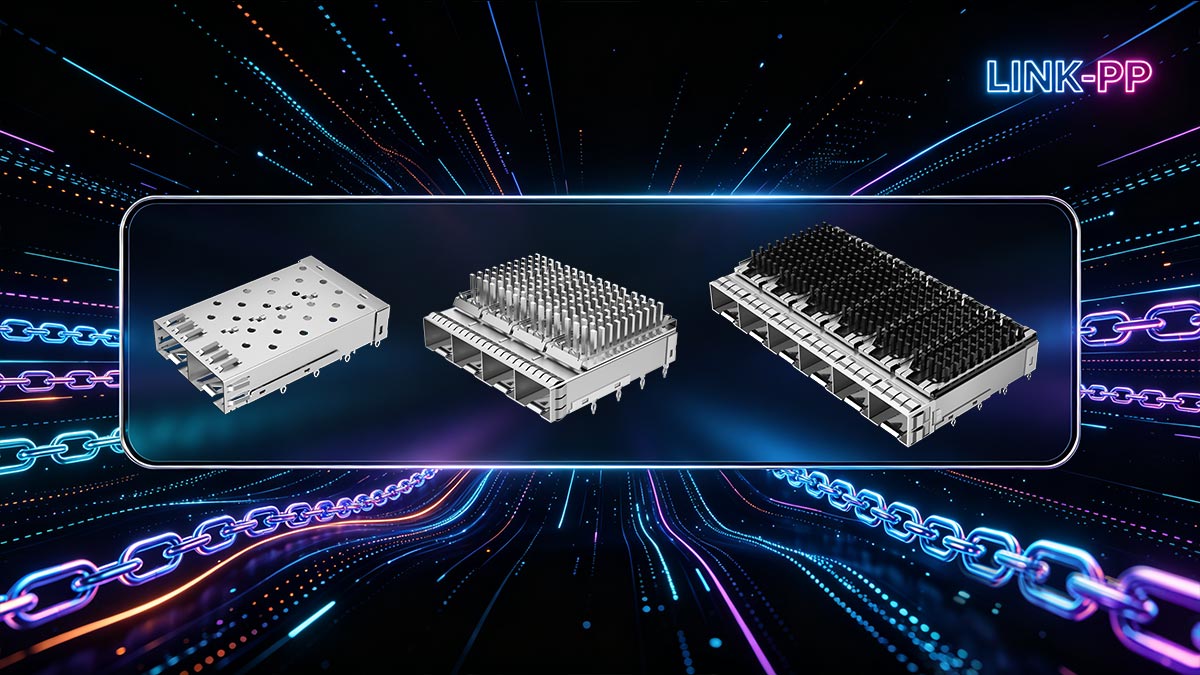
The right SFP electrical connector depends on four practical factors: data rate, board space, compliance requirements, and sourcing strategy. For 1G designs, standard SFP connectors are usually sufficient. For 10G, 25G, and faster platforms, the connector must support tighter signal integrity, stronger EMI control, and a validated cage-to-board layout. The safest choice is a connector that matches the target speed class, PCB footprint, and mechanical specification of the final system.
How to Choose the Right SFP Electrical Connector

1) Start with the target data rate

Your first decision should be the required speed class.

  • 1G SFP for legacy or general-purpose Ethernet
  • شنومكسغ سفب + for mainstream high-speed networking
  • 25G SFP28 for newer data center and access designs

Higher speeds place stricter demands on insertion loss, impedance control, and PCB routing quality. A connector that works well at 1G may not be suitable for a 25G design.

2) Check available board space

SFP ports are compact, but the full assembly still needs enough room for:

  • the connector footprint
  • the cage body
  • keep-out clearance
  • latch and module insertion space
  • trace routing on the host PCB

If the board is dense, the connector choice should be matched to the cage geometry and front-panel layout before finalizing the design.

3) Verify compliance requirements

For production hardware, the connector should align with the relevant SFP mechanical and electrical specifications. That includes:

  • تسلسل الاتصال
  • 100 Ω differential routing expectations
  • grounding and shield behavior
  • hot-plug reliability
  • compatibility with the intended module family

Compliance is especially important in products that must pass EMC, interoperability, or carrier-grade validation.

4) Plan the sourcing strategy

Connector selection is not only a technical decision. It also affects lead time, availability, and long-term supply stability. For OEM and ODM projects, it is better to choose a part that is:

  • على نطاق واسع
  • documented with clear footprint data
  • compatible with the target cage
  • supported by a reliable manufacturer

For teams sourcing complete SFP modules or building around a proven ecosystem, the LINK-PP المتجر الرسمي is a practical place to explore compatible SFP modules and related network connectivity solutions.

قائمة التحقق النهائية للاختيار

Use this quick rule before finalizing the design:

  • Choose by speed first
  • Confirm footprint and cage fit second
  • Check EMI and grounding third
  • Select a stable supplier last

خاتمة

A good SFP electrical connector is the one that matches your electrical target, mechanical constraints, and supply needs at the same time. For stable performance and easier deployment, always evaluate the connector as part of the full SFP port system, not as an isolated component.

فيديو

المزيد
صورة غلاف الفيديو
01:11
خدمة التوصيل العالمية | LINK-PP
يونيو 26، 2024
1.2k
888