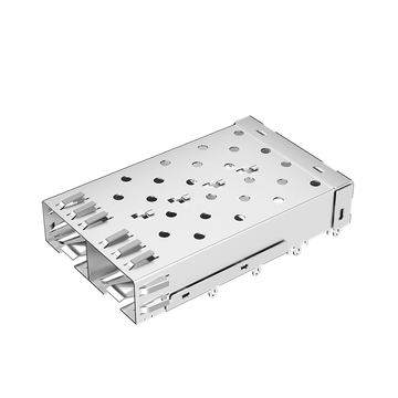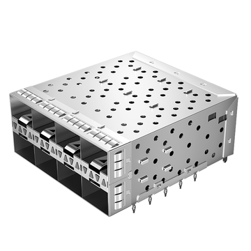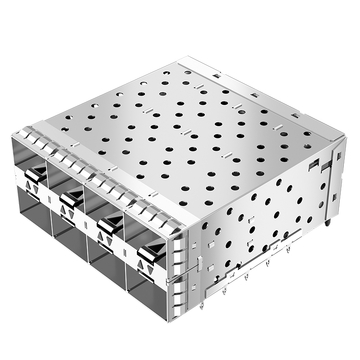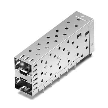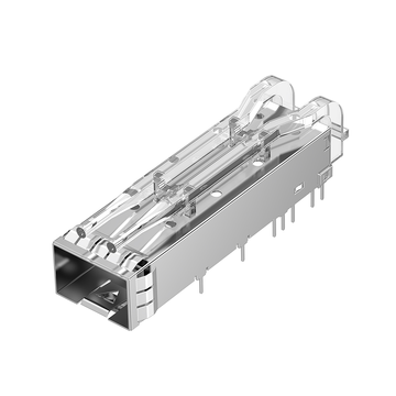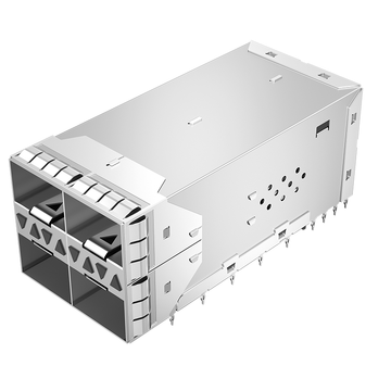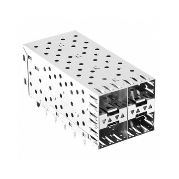
صُممت الأقفاص البصرية القياسية لتوفير دعم ميكانيكي موثوق، ومحاذاة أجهزة الإرسال والاستقبال، والتثبيت، والحماية، والتكامل الحراري ضمن منصات الشبكات الشائعة. بالنسبة للمعدات القياسية، غالبًا ما يفي القفص الجاهز بهذه المتطلبات بكفاءة. مع ذلك، تجمع أجهزة الشبكات الحديثة بشكل متزايد بين كثافة منافذ أعلى، وتصميمات لوحات دوائر مطبوعة أكثر دقة، وهياكل متخصصة، ومتطلبات حرارية وتوافق كهرومغناطيسي أكثر صرامة، مما يجعل الأبعاد والتكوينات القياسية أقل ملاءمةً للاستخدام العالمي.
هنا تبرز أهمية تخصيص قفص الألياف الضوئية. قد يبدو القفص متوافقًا ميكانيكيًا، ولكنه قد يُسبب مشاكل تتعلق بمساحة لوحة الدوائر المطبوعة، وتباعد المنافذ، وسهولة الوصول إلى جهاز الإرسال والاستقبال، وتدفق الهواء، وتبديد الحرارة، أو الحماية الكهرومغناطيسية. وتزداد هذه المشاكل أهميةً عند دمج واجهات الإرسال والاستقبال الضوئية من نوع SFP أو SFP28 أو QSFP أو غيرها في منصات خاصة أو قديمة أو عالية الكثافة.
تتناول هذه المقالة الحالات التي يصبح فيها القفص البصري القياسي الجاهز غير مناسب، وكيف يمكن للتصميم المخصص معالجة هذه القيود. وتشمل ما يلي:
- نقاط الفشل الشائعة في المجالات الميكانيكية، والموصلات، والحرارية، والتداخل الكهرومغناطيسي.
- متطلبات متخصصة تتطلب عادةً تخصيصًا.
- المعايير الرئيسية للقفص البصري التي يمكن تعديلها.
- كيفية LINK-PPيتبع فريق التخصيص التابع لنا أساليب التصميم، والنمذجة الأولية، والتحقق.
- معايير عملية لتقييم قفص بصري مخصص قبل تركيبه.
يساعد فهم هذه العوامل المهندسين على اختيار حل قفص يناسب المنصة بأكملها بدلاً من تكييف نظام متخصص حول تصميم قياسي ثابت.
☑️ لماذا تفشل الأقفاص البصرية القياسية الجاهزة في المنصات المتخصصة؟
عادةً ما يصبح قفص الألياف الضوئية القياسي الجاهز غير مناسب عندما لا تتوافق خصائصه الميكانيكية أو الحرارية أو خصائص واجهة المستخدم أو خصائص التداخل الكهرومغناطيسي مع المتطلبات الفعلية للمنصة المضيفة. قد يفي القفص نفسه بالأبعاد الصناعية الشائعة، ولكنه مع ذلك يُسبب مشاكل في التكامل عند استخدامه في محولات عالية الكثافة، أو معدات شبكات خاصة، أو أنظمة قديمة، أو أجهزة متخصصة أخرى.
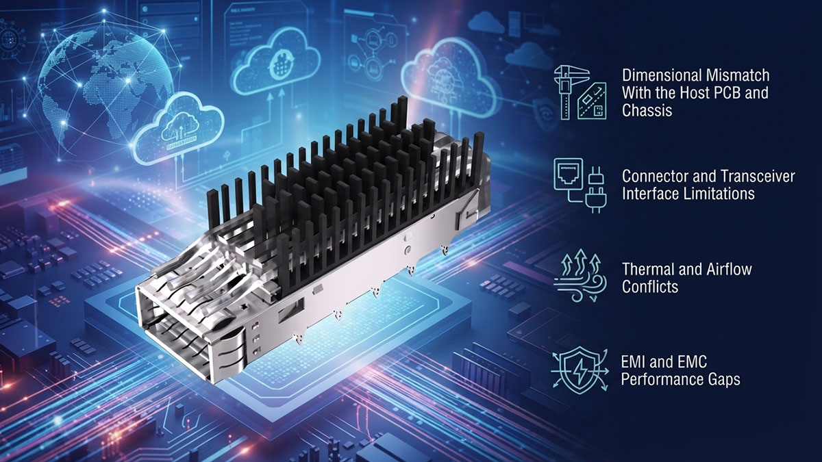
عدم تطابق الأبعاد مع لوحة الدوائر المطبوعة المضيفة والهيكل
يُعدّ عدم تطابق الأبعاد أحد أكثر الأسباب شيوعًا لعدم إمكانية دمج قفص بصري قياسي بشكل صحيح. حتى الاختلاف الطفيف في المساحة، أو موضع التركيب، أو الارتفاع الكلي، قد يتداخل مع لوحة الدوائر المطبوعة، أو الهيكل، أو اللوحة الأمامية، أو المكونات المجاورة.
تشمل المشاكل النموذجية ما يلي:
- بصمات لوحة الدوائر المطبوعة التي لا تتطابق مع نقاط تثبيت القفص.
- ارتفاع القفص الذي يتعارض مع المكونات أو المشتتات الحرارية القريبة.
- عدم وجود مسافة كافية بين المنافذ البصرية المتجاورة.
- فتحات اللوحة الأمامية التي لا تتوافق مع منافذ القفص.
- عمق القفص يتجاوز مساحة الهيكل المتاحة.
- ميزات التثبيت التي لا يمكنها استيعاب بنية لوحة الدوائر المطبوعة الحالية.
تكتسب هذه المسائل أهمية خاصة في معدات الشبكات المدمجة، حيث يجب أن يتناسب القفص البصري مع غلاف ميكانيكي محدد بدقة. فالقفص الذي يفي بمواصفات الأبعاد القياسية ليس بالضرورة متوافقًا مع جميع منصات الاستضافة.
قيود واجهة الموصل وجهاز الإرسال والاستقبال
قد يتعطل قفص الألياف الضوئية أيضًا عندما لا يتوافق تكوين واجهته مع ترتيب جهاز الإرسال والاستقبال والموصل المطلوب من قبل المنصة. ولا يقتصر التوافق على مجرد تحديد ما إذا كان بإمكان وحدة SFP أو QSFP الدخول فعليًا إلى القفص.
تشمل الاعتبارات الرئيسية للواجهة ما يلي:
- متطلبات عامل الشكل SFP و SFP+ و SFP28 و QSFP و QSFP28.
- ميل الفتحة والمسافة بين الأقفاص المتجاورة.
- تحديد موضع الموصل بالنسبة للوحة الدوائر المطبوعة.
- عملية إدخال وإخراج الوحدات النمطية.
- سهولة الوصول إلى المزلاج ولسان السحب وآلية التثبيت.
- محاذاة بين المنفذ البصري وفتحة الهيكل.
بالنسبة للمنصات عالية الكثافة، قد تصبح المسافة القياسية بين المنافذ محدودة للغاية. وقد تتطلب أجهزة الإرسال والاستقبال المتقاربة ترتيبًا مخصصًا للقفص للحفاظ على خلوص ميكانيكي كافٍ مع الحفاظ على إمكانية الوصول إلى اللوحة الأمامية.
تعارضات الحرارة وتدفق الهواء
قد تجعل القيود الحرارية قفصًا بصريًا قياسيًا غير مناسب حتى وإن كان تركيبه الميكانيكي مقبولًا. يتفاعل القفص مع غلاف جهاز الإرسال والاستقبال، ومشتت الحرارة، والوصلة الحرارية، وتدفق الهواء المحيط، لذا فإن هندسته تؤثر بشكل مباشر على فعالية نظام التبريد.
تشمل المشاكل الشائعة المتعلقة بالحرارة وتدفق الهواء ما يلي:
- انخفاض تدفق الهواء حول أجهزة الإرسال والاستقبال المثبتة بكثافة.
- عدم كفاية الاتصال بين الوحدة وهيكل تبديد الحرارة.
- التداخل بين القفص ومشتتات الحرارة المجاورة.
- هندسة القفص التي تعيق مسار تدفق الهواء المقصود.
- مساحة محدودة لمكونات إدارة الحرارة الإضافية.
مع تطور معدات الشبكات الضوئية نحو كثافة منافذ أعلى وسرعات إرسال واستقبال أعلى، تزداد أهمية إدارة الحرارة. لذا، قد يتطلب تصميم قفص متوافق ميكانيكيًا مراعاة تصميمية إضافية للحفاظ على بيئة تشغيل مناسبة.
فجوات الأداء في مجال التوافق الكهرومغناطيسي والتداخل الكهرومغناطيسي
قد يُصبح القفص البصري القياسي مُشكلاً أيضاً عندما تتطلب المنصة توافقاً كهرومغناطيسياً عالياً. ولأن القفص يُمكن أن يُشكّل جزءاً من هيكل الحماية والتأريض حول الواجهة البصرية، فإن وجود فجوات أو عدم كفاية التوصيل الكهربائي قد يُؤدي إلى مسارات تداخل كهرومغناطيسي غير مرغوب فيها.
تشمل المشكلات المحتملة المتعلقة بالتوافق الكهرومغناطيسي ما يلي:
- الفجوات بين القفص والهيكل.
- عدم اكتمال استمرارية التأريض.
- عدم كفاية التلامس بين زنبرك الإصبع.
- عدم كفاية الحماية حول الواجهة البصرية.
- التفاوتات الميكانيكية التي تقلل من موثوقية التأريض.
- التفاعل بين هيكل القفص والدوائر الإلكترونية عالية السرعة القريبة.
هذا يعني أنه لا يمكن دائمًا فصل أداء التوافق الكهرومغناطيسي عن التصميم الميكانيكي. قد تحتاج أبعاد القفص ونقاط التلامس وهياكل الحماية وطرق التركيب إلى العمل معًا لتحقيق سلوك التوافق الكهرومغناطيسي المطلوب.
☑️ ما هي متطلبات التخصيص التي تتجاوز مواصفات القفص القياسية؟
يصبح التخصيص ضروريًا عندما يتطلب قفص بصري تلبية متطلبات ميكانيكية أو حرارية أو متعلقة بالتوافق الكهرومغناطيسي أو التكامل خاصة بالتطبيق، وهي متطلبات لا يمكن تحقيقها باستخدام تكوين قياسي. فبدلاً من تغيير المنصة الأساسية لاستيعاب قفص قياسي، يمكن تصميم قفص بصري مخصص ليناسب لوحة الدوائر المطبوعة والهيكل وجهاز الإرسال والاستقبال وظروف التشغيل الفعلية.
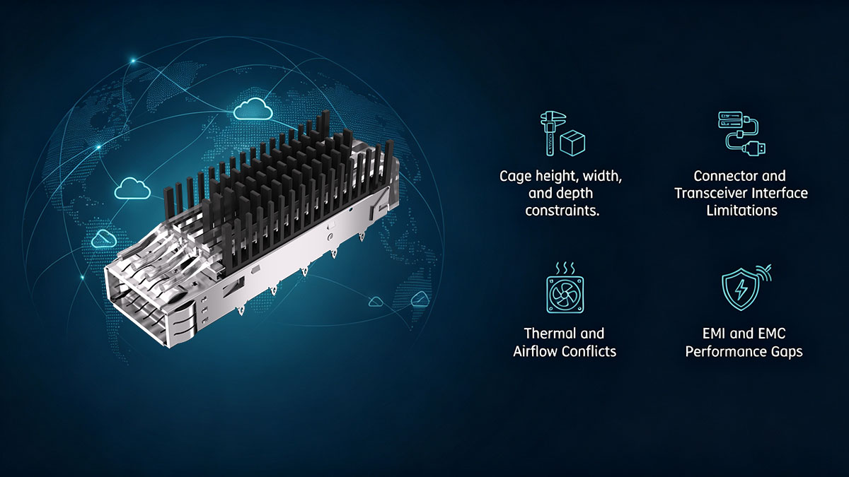
أبعاد غير قياسية وبصمات لوحة الدوائر المطبوعة
تُعدّ الأبعاد غير القياسية من أبرز الأسباب التي تدعو إلى تجاوز استخدام الأقفاص البصرية الجاهزة. إذ يُمكن تصميم قفص مخصص يتناسب مع مساحة اللوحة المتاحة، وهندسة التركيب، والظروف الميكانيكية للمنصة المستهدفة.
قد تشمل المتطلبات النموذجية ما يلي:
- طول أو عرض أو ارتفاع القفص حسب الطلب.
- أبعاد بصمة لوحة الدوائر المطبوعة المعدلة.
- مواقع فتحات التثبيت غير القياسية.
- مواقع المنافذ المزاحة.
- تقليل الخلوص حول المكونات المجاورة.
- تصميم هندسي خاص للقفص يناسب المساحة المحدودة للهيكل.
يُعدّ هذا النهج مفيدًا بشكل خاص عندما تكون لوحة الدوائر المطبوعة الحالية مصممة مسبقًا ولا يمكن تعديلها بسهولة. ويمكن أن يساعد مطابقة القفص مع تصميم اللوحة المُعتمد على تجنب إعادة تصميم الدوائر المحيطة والهياكل الميكانيكية دون داعٍ.
ترتيبات المنافذ المخصصة ومجموعات الأقفاص
غالباً ما يصبح ترتيب المنافذ مسألة تخصيص عندما لا توفر المسافات القياسية بين الأقفاص الكثافة المطلوبة للمنافذ أو تصميم اللوحة الأمامية. يمكن لتجميعات الأقفاص المخصصة استيعاب أعداد ومنافذ ومسافات مختلفة، بالإضافة إلى ترتيبات هيكلية متنوعة، وفقاً لتصميم المنصة.
الشروط الشائعة تشمل:
- تكوينات قفص أحادية المنفذ ومتعددة المنافذ.
- منافذ بصرية متجاورة.
- ترتيبات الأقفاص المتراصة.
- تجميعات الأقفاص المتصلة للواجهات عالية الكثافة.
- تكوينات المنافذ المختلطة لأشكال أجهزة الإرسال والاستقبال المختلفة.
- تم تخصيص مسافة فتحات المنافذ لتتناسب مع فتحات اللوحة الأمامية.
لا يقتصر الهدف على مجرد تركيب المزيد من المنافذ في مساحة أقل، بل يجب أن يحافظ التصميم أيضاً على سهولة الوصول إلى جهاز الإرسال والاستقبال، والاستقرار الميكانيكي، وتدفق الهواء، والمسافة الكافية بين المكونات المتجاورة.
متطلبات خاصة لتبديد الحرارة
قد تتجاوز المتطلبات الحرارية قدرات القفص القياسي عندما تولد الوحدات البصرية حرارة أكبر أو عندما تكون قدرة التبريد للمنصة المضيفة محدودة. ويمكن للتخصيص أن ينسق بنية القفص مع مشتتات الحرارة، والوصلات الحرارية، ومسار تدفق الهواء في النظام.
قد يعالج التصميم الحراري المتخصص ما يلي:
- أبعاد ومواصفات مشتتات الحرارة المخصصة.
- تحديد موضع المشتت الحراري بالنسبة لجهاز الإرسال والاستقبال.
- وضع مادة التوصيل الحراري.
- المسافة الفاصلة بين المكونات الحرارية ولوحة الدوائر المطبوعة.
- اتجاه تدفق الهواء والعوائق المحتملة.
- متطلبات تبديد الحرارة في التكوينات البصرية عالية الكثافة.
لذا، ينبغي اعتبار القفص والتجميع الحراري حلاً ميكانيكياً متكاملاً. قد يكون القفص الذي يتناسب مع لوحة الدوائر المطبوعة ولكنه يُعيق تدفق الهواء أو يمنع التلامس الحراري الفعال غير مناسب للتطبيق.
متطلبات الحماية والتأريض المخصصة للحماية من التداخل الكهرومغناطيسي
قد تتجاوز متطلبات التوافق الكهرومغناطيسي (EMI) وخصائص الحماية الكهرومغناطيسية (EMC) خصائص القفص القياسي، خاصةً عند وضع الواجهة البصرية بالقرب من دوائر حساسة عالية السرعة. ويمكن دمج ميزات حماية وتأريض مخصصة في تصميم القفص لتحسين التوافق مع المنصة المضيفة.
تشمل مجالات التخصيص المحتملة ما يلي:
- هياكل الحماية المحيطة بالمنافذ البصرية.
- نقاط تأريض مخصصة.
- مواقع وتكوينات أصابع الزنبرك.
- اتصال كهربائي بين القفص والهيكل.
- ضمان استمرارية الحماية بين مجموعات الأقفاص المتجاورة.
- ميزات ميكانيكية تحافظ على اتصال تأريض موثوق.
يجب أن تتوافق هذه الخصائص مع التفاوتات الميكانيكية للهيكل وبنية التثبيت. لذا، يتطلب التحكم الفعال في التداخل الكهرومغناطيسي مراعاة تصميم الحماية والتأريض منذ البداية، بدلاً من إضافتهما بعد الانتهاء من تصميم الهيكل الهندسي للهيكل.
متطلبات التثبيت الميكانيكي وإمكانية الوصول
قد تتطلب المنصات المتخصصة أيضًا ميزات تثبيت ميكانيكية وتسهيلات للصيانة تختلف عن تصميمات الأقفاص القياسية. يجب أن يسمح القفص ببقاء أجهزة الإرسال والاستقبال في مكانها بشكل آمن مع توفير وصول كافٍ للتركيب والإزالة والصيانة.
قد تشمل عملية التخصيص ما يلي:
- إجراءات إدخال وإخراج جهاز الإرسال والاستقبال.
- سهولة الوصول إلى لسان السحب والمشبك.
- قيود الوصول إلى اللوحة الأمامية.
- ميزات الاحتفاظ بالبيانات لعمليات الخدمة المتكررة.
- الاستقرار الميكانيكي في ظل الاهتزاز أو الحركة.
- الخلوص بين القفص ومكونات الهيكل المحيطة به.
تُعدّ هذه المتطلبات ذات أهمية خاصة في المعدات التي تخضع وحداتها البصرية للصيانة بشكل متكرر أو التي تكون فيها مساحة اللوحة الأمامية محدودة للغاية. ويمكن لتصميم مخصص للتثبيت والوصول أن يضمن عدم تأثر الموثوقية الميكانيكية سلبًا بالصيانة العملية.
☑️ ما هي معايير القفص البصري التي يمكن تخصيصها؟
يمكن تخصيص القفص البصري وفقًا لعدة معايير مترابطة، تشمل الأبعاد الميكانيكية، وتكوين المنافذ، والهياكل الحرارية، والحماية من التداخل الكهرومغناطيسي، وخصائص التركيب. ويُعدّ النهج الأمثل هو التعامل مع القفص كوحدة كهروميكانيكية متكاملة بدلاً من تعديل أبعاده الخارجية فقط.
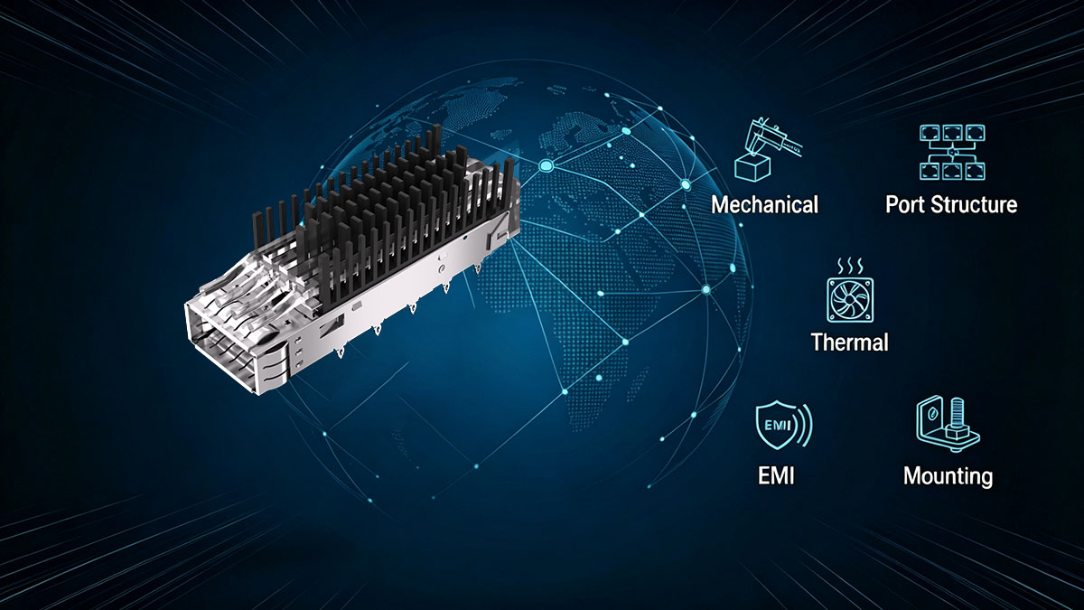
يمكن تلخيص مجالات التخصيص الرئيسية على النحو التالي:
| منطقة التخصيص | المعلمات النموذجية | الهدف الأساسي للتصميم |
|---|---|---|
| ميكانيكي أو | الطول، العرض، الارتفاع، المساحة | تكامل النظام الأساسي |
| هيكل الميناء | عدد المنافذ، والتباعد، والترتيب | الكثافة وسهولة الوصول |
| ملابس حرارية | مشتت حراري، واجهة حرارية، مسار تدفق الهواء | التحكم في درجة الحرارة |
| EMI | التدريع، نقاط التأريض، أطراف زنبركية | أداء EMC |
| متزايد | ألسنة، دبابيس، ثقوب، ميزات تثبيت | استقرار لوحة الدوائر المطبوعة/الهيكل |
ترتبط هذه المعايير ارتباطًا وثيقًا. فعلى سبيل المثال، قد يؤدي زيادة كثافة المنافذ إلى تقليل مساحة تدفق الهواء المتاحة، بينما قد يؤثر تغيير أبعاد القفص على محاذاة التركيب ومواقع التلامس الكهرومغناطيسي. لذا، يجب تقييم القفص البصري المُصمم خصيصًا كوحدة متكاملة بدلًا من مجموعة من التعديلات المنفصلة.
الهندسة الميكانيكية وهيكل التركيب
تُعدّ الهندسة الميكانيكية عادةً أساسًا لتخصيص قفص البصريات، إذ يجب أن يتوافق القفص فعليًا مع لوحة الدوائر المطبوعة، وجهاز الإرسال والاستقبال، والهيكل، واللوحة الأمامية. ويمكن تعديل الأبعاد المخصصة وميزات التركيب لتلائم القيود الخاصة بكل منصة.
قد تشمل المعايير الميكانيكية الرئيسية ما يلي:
- الطول الإجمالي للقفص، وعرضه، وارتفاعه.
- بصمة لوحة الدوائر المطبوعة ومواقع فتحات التثبيت.
- ألسنة التثبيت، أو الدبابيس، أو غيرها من هياكل التثبيت.
- موضع المنفذ بالنسبة للوحة الدوائر المطبوعة.
- التخليص الداخلي والخارجي للمكونات.
- محاذاة اللوحة الأمامية وخلوص الهيكل.
- التفاوتات الأبعادية للمكونات المتزاوجة.
تحدد هذه التفاصيل ما إذا كان من الممكن تركيب القفص بشكل صحيح والحفاظ على استقراره الميكانيكي أثناء إدخال جهاز الإرسال والاستقبال وإزالته وصيانته الروتينية.
كثافة الموانئ وترتيبها
يُحدد تكوين المنافذ كيفية وضع أجهزة الإرسال والاستقبال الضوئية ضمن المساحة المتاحة. ويمكن تعديل عدد المنافذ والمسافات بينها وترتيبها حسب الحاجة عندما لا يوفر القفص القياسي الكثافة أو التصميم المادي المطلوب.
تشمل الاعتبارات التصميمية المهمة ما يلي:
- عدد المنافذ الضوئية.
- ميل البوابات والمسافة بين المراكز.
- تكوينات متجاورة أو مكدسة.
- تركيبات الأقفاص للمنصات عالية الكثافة.
- محاذاة المنفذ مع فتحة الهيكل.
- مساحة كافية لمزالج جهاز الإرسال والاستقبال وعلامات السحب.
- الفصل بين أنواع الواجهات البصرية المختلفة.
بالنسبة لتطبيقات SFP وSFP28 وQSFP والتطبيقات ذات الكثافة العالية، يجب أن يوازن تصميم المنافذ بين استغلال المساحة وسهولة الوصول والمتطلبات الحرارية. إن مجرد تقليل المسافة بين المنافذ دون مراعاة هذه العوامل قد يُسبب مشاكل في التركيب أو التبريد.
مشتت حراري ومجموعة حرارية
يركز التخصيص الحراري على الحفاظ على نقل الحرارة بكفاءة مع ضمان التوافق الميكانيكي لمجموعة القفص. وبحسب التطبيق، يمكن تنسيق القفص مع مشتتات الحرارة، والوصلات الحرارية، وبنية تدفق الهواء للمنصة.
تشمل المعايير الحرارية ذات الصلة ما يلي:
- أبعاد وشكل المشتت الحراري.
- موضع المشتت الحراري بالنسبة لجهاز الإرسال والاستقبال.
- موقع مادة التوصيل الحراري.
- مساحة التلامس بين المكونات الحرارية.
- مساحة خالية حول هياكل تبديد الحرارة.
- اتجاه تدفق الهواء ومساحة التهوية المتاحة.
يجب ألا يعيق الهيكل الحراري المُصمم خصيصاً المكونات المجاورة أو مسار تدفق الهواء المقصود. وهذا أمر بالغ الأهمية خاصةً بالنسبة للواجهات البصرية عالية الكثافة، حيث يمكن لوحدات متعددة أن تُركّز الحرارة داخل غلاف صغير نسبياً.
ميزات الحماية من التداخل الكهرومغناطيسي والتأريض
تُعالج عملية تخصيص التوافق الكهرومغناطيسي دور القفص في الحماية والتأريض حول الواجهات البصرية. ويمكن تحديد مواقع هياكل الحماية وميزات التوصيل الكهربائي وفقًا للخصائص الكهرومغناطيسية والميكانيكية للمنصة المستهدفة.
تشمل معايير التخصيص المحتملة ما يلي:
- هيكل الحماية والتغطية.
- مواقع التأريض.
- وضع الأصابع بشكل زنبركي.
- نقاط التلامس بين القفص والهيكل.
- هندسة التلامس والضغط الميكانيكي.
- ضمان استمرارية الحماية بين مجموعات الأقفاص المتجاورة.
تُعدّ التفاوتات الميكانيكية مهمة هنا، لأنه حتى بنية التأريض المصممة جيدًا قد لا تعمل بكفاءة إذا كانت نقاط التلامس غير محاذية أو غير متصلة بشكل كافٍ. لذا، ينبغي دمج اعتبارات التداخل الكهرومغناطيسي في تصميم القفص بدلًا من اعتبارها تعديلًا نهائيًا.
☑️ كيف يعمل LINK-PPهل يستطيع فريق التخصيص لدينا حل متطلبات الأقفاص غير القياسية؟
LINK-PPيُعالج فريق التخصيص لدينا متطلبات الأقفاص البصرية غير القياسية من خلال البدء بالمنصة المستهدفة بدلاً من فرض تصميم غير متوافق مع تكوين قفص ثابت. وتُترجم هذه العملية المتطلبات الميكانيكية والحرارية ومتطلبات الواجهة والتوافق الكهرومغناطيسي إلى مجموعة أقفاص بصرية مُخصصة يُمكن تقييمها مقابل نظام الشبكة الكامل.
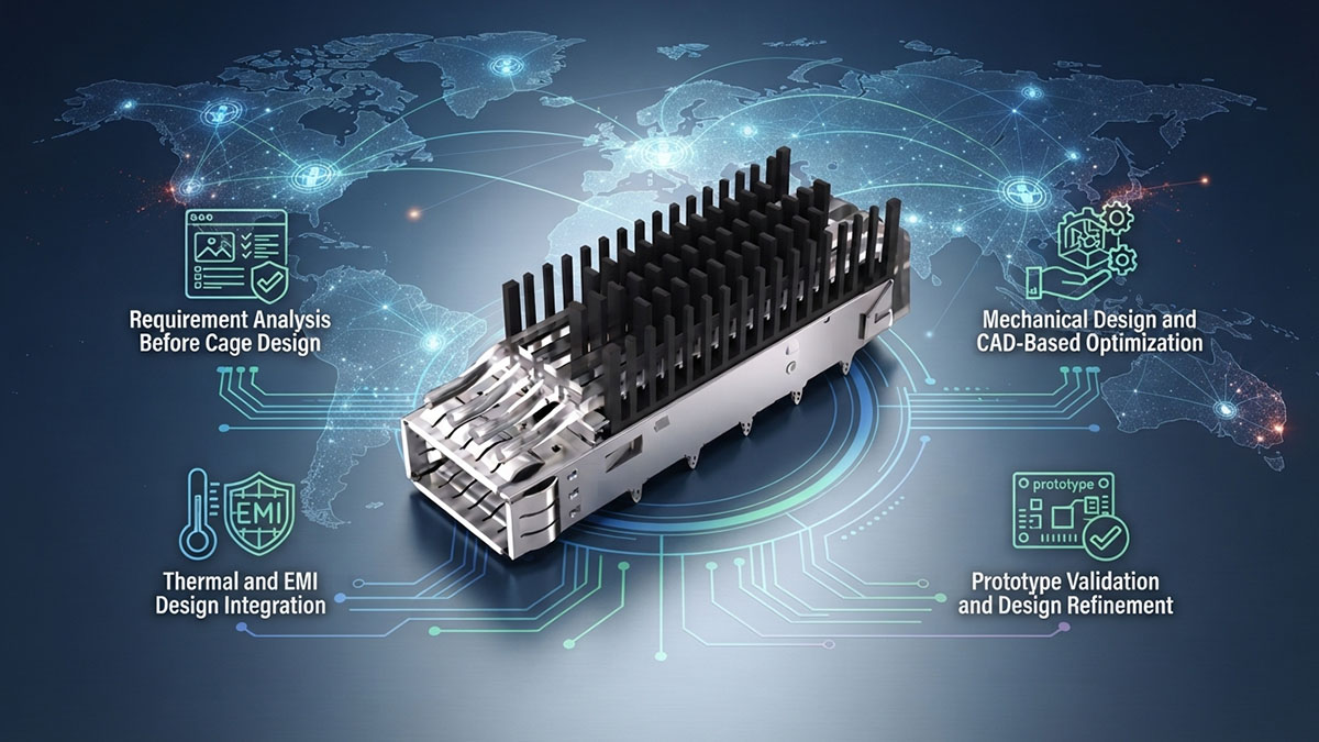
تحليل المتطلبات قبل تصميم القفص
تتمثل الخطوة الأولى في تحديد متطلبات التطبيق الفعلية قبل تحديد بنية القفص. وهذا يمنع التصميم من التركيز على بُعد واحد مع إغفال القيود الأخرى في المنصة.
يتضمن تحليل المتطلبات عادةً ما يلي:
- نوع وشكل جهاز الإرسال والاستقبال الضوئي.
- عدد المنافذ الضوئية المطلوبة.
- أبعاد لوحة الدوائر المطبوعة ومنطقة التركيب المتاحة.
- قيود الهيكل واللوحة الأمامية.
- تباعد المنافذ وسهولة الوصول إليها.
- متطلبات تبديد الحرارة وتدفق الهواء.
- اعتبارات التوافق الكهرومغناطيسي والتأريض.
- متطلبات إدخال جهاز الإرسال والاستقبال واستخراجه وصيانته.
يُتيح تعريف المتطلبات الواضح لفريق التخصيص تحديد أهداف تصميم قابلة للقياس. كما يُساعد في تحديد ما إذا كان التحدي الرئيسي يتمثل في التوافق الميكانيكي، أو كثافة المنافذ، أو الإدارة الحرارية، أو الحماية من التداخل الكهرومغناطيسي، أو مزيج من عدة عوامل.
التصميم الميكانيكي والتحسين القائم على التصميم بمساعدة الحاسوب
بمجرد تحديد المتطلبات، يمكن تصميم هندسة القفص بما يتناسب مع القيود الفيزيائية للمنصة المضيفة. يتيح التصميم القائم على برامج التصميم بمساعدة الحاسوب (CAD) مراجعة الأبعاد الحرجة، ومواقع التركيب، ومحاذاة المنافذ، ومسافات الخلوص بين المكونات قبل الإنتاج الفعلي.
يمكن أن تركز عملية التصميم على ما يلي:
- تحويل أبعاد المنصة إلى هندسة القفص.
- مطابقة بصمة لوحة الدوائر المطبوعة ومواقع التركيب.
- التحقق من التداخل مع المكونات المجاورة.
- تحسين محاذاة المنافذ مع اللوحة الأمامية.
- الحفاظ على مسافة كافية لإدخال وإخراج جهاز الإرسال والاستقبال.
- مراجعة التفاوتات البُعدية لمناطق التزاوج الحرجة.
يُعد هذا النهج مفيدًا بشكل خاص لمعدات الشبكات الخاصة أو عالية الكثافة لأنه يمكن تصميم القفص حول المنصة الحالية بدلاً من الحاجة إلى تعديلات واسعة النطاق على لوحة الدوائر المطبوعة أو الهيكل.
تكامل التصميم الحراري والتوافق الكهرومغناطيسي
يجب مراعاة الإدارة الحرارية والتحكم في التداخل الكهرومغناطيسي جنبًا إلى جنب مع التصميم الميكانيكي لأن التغييرات في هندسة القفص يمكن أن تؤثر على كل من تدفق الهواء والحماية الكهرومغناطيسية. LINK-PPوبالتالي، يمكن لعملية التخصيص الخاصة بـ "s" أن تأخذ هذه المتطلبات في الاعتبار أثناء تطوير القفص بدلاً من التعامل معها كأفكار لاحقة منفصلة.
تشمل الاعتبارات التصميمية المهمة ما يلي:
- تنسيق أبعاد القفص مع موضع المشتت الحراري.
- الحفاظ على مسار تدفق الهواء المقصود.
- توفير اتصال حراري مناسب مع مجموعة جهاز الإرسال والاستقبال.
- تحديد مواقع نقاط التأريض وفقًا لهيكل المنصة.
- دمج خصائص الحماية حول الواجهات البصرية.
- الحفاظ على الاتصال الكهربائي بين القفص والهيكل عند الحاجة.
يمكن أن يساهم دمج هذه العوامل مبكراً في تقليل التداخلات بين الهياكل الحرارية، وميزات التثبيت، ومكونات الحماية، والدوائر المجاورة. وبالتالي، يُفضل تقييم القفص البصري المصمم خصيصاً كجزء من المنصة الكاملة بدلاً من اعتباره مكوناً معدنياً معزولاً.
التحقق من صحة النموذج الأولي وتحسين التصميم
ينبغي التحقق من صحة تصميم القفص المخصص فعلياً قبل اعتماد التصميم النهائي. يوفر النموذج الأولي فرصة لتحديد المشكلات الميكانيكية أو الحرارية أو المتعلقة بسهولة الوصول أو الحماية، والتي قد لا تتضح تماماً من التصميم البُعدي وحده.
يمكن أن يشمل التحقق من صحة النموذج الأولي ما يلي:
- التحقق من التوافق المادي مع لوحة الدوائر المطبوعة المستهدفة أو الهيكل.
- التحقق من إدخال جهاز الإرسال والاستقبال وإخراجه.
- فحص محاذاة المنافذ وسهولة الوصول إلى اللوحة الأمامية.
- تقييم وضعية المشتت الحراري والوصلة الحرارية.
- فحص قيود تدفق الهواء.
- مراجعة توصيلات التأريض والحماية.
- تحسين الأبعاد أو السمات الهيكلية بناءً على نتائج الاختبار.
تُعدّ هذه العملية التكرارية ذات قيمة خاصة للتطبيقات المتخصصة التي لا تسمح بأي تداخل ميكانيكي أو أخطاء في التكامل. فمن خلال تحسين التصميم قبل الإنتاج، يمكن تحويل عملية التخصيص من متطلبات خاصة بمنصة معينة إلى تجميع قفص قابل للتكرار ومناسب للاستخدام المقصود.
☑️ متى ينبغي على المهندسين اختيار تصميم القفص المخصص بدلاً من التصميم القياسي؟
ينبغي على المهندسين اختيار تصميم قفص بصري مخصص عندما لا يفي القفص القياسي بمتطلبات المنصة الميكانيكية أو الحرارية أو الكثافة أو التداخل الكهرومغناطيسي أو سهولة الوصول للصيانة، دون المساس بتصميم النظام ككل. ويكتسب التصميم المخصص أهمية خاصة عندما يؤدي تعديل لوحة الدوائر المطبوعة أو الهيكل لاستيعاب قفص ثابت إلى زيادة التعقيد الهندسي أو مخاطر التكامل.

معدات الشبكات عالية الكثافة
تُعدّ معدات الشبكات عالية الكثافة خيارًا مثاليًا لتصميم أقفاص مخصصة، نظرًا لأن المساحة المحدودة للوحة الدوائر المطبوعة واللوحة الأمامية قد تجعل التباعد القياسي للمنافذ غير عملي. ومع ازدياد عدد الواجهات الضوئية، يجب أن يوازن القفص بين كثافة المنافذ وسهولة الوصول إليها، وتدفق الهواء، والإدارة الحرارية.
يمكن النظر في التخصيص عندما تتطلب المنصة ما يلي:
- واجهات بصرية متقاربة مثل SFP أو SFP28 أو QSFP أو ما شابهها.
- منافذ متعددة ضمن منطقة محدودة في اللوحة الأمامية.
- تكوينات الأقفاص المتراصة أو المتصلة.
- تم تحسين مسافة المنافذ لزيادة كثافة الواجهة.
- مساحة إضافية لإدخال جهاز الإرسال والاستقبال وإخراجه.
- الهياكل الحرارية التي يجب أن تتناسب مع مساحة واجهة بصرية صغيرة.
لا يقتصر الهدف على زيادة عدد المنافذ فحسب، بل يجب أن يحافظ تصميم القفص على خلوص ميكانيكي كافٍ وأن يدعم الخصائص الحرارية وخصائص تدفق الهواء للمنصة بأكملها.
منصات الأجهزة الخاصة أو المتخصصة
غالباً ما تستخدم الأجهزة الخاصة والمتخصصة تصميمات ميكانيكية لا تتوافق مباشرةً مع أبعاد القفص القياسية. في هذه الحالات، يمكن أن يوفر التخصيص طريقة عملية لدمج الواجهات البصرية دون إعادة تصميم منصة قائمة.
تُعدّ التخصيصات ذات أهمية خاصة عندما تحتوي المعدات على:
- تصميم لوحة دوائر مطبوعة غير قياسي.
- هيكل هيكلي خاص.
- فتحات فريدة في اللوحة الأمامية.
- القيود الميكانيكية القديمة.
- مواقع التثبيت الحالية التي لا يمكن نقلها.
- تحديد موضع الواجهة البصرية المتخصصة.
بالنسبة للأجهزة القديمة، يمكن أن يساعد قفص بصري مصمم خصيصًا في الحفاظ على بنية لوحة الدوائر المطبوعة والهيكل الحاليين. فبدلاً من إعادة تصميم الأجهزة المحيطة فقط لاستيعاب قفص جاهز، يمكن تكييف القفص مع هندسة النظام القائمة.
تطبيقات عالية الأداء وعالية الحمل الحراري
قد تتطلب المنصات البصرية عالية الأداء تكاملاً حرارياً أكثر دقة مما يوفره القفص القياسي. كما أن نشر أجهزة الإرسال والاستقبال عالية السرعة والتكوينات البصرية الكثيفة يزيد من أهمية تبديد الحرارة والتوصيل الحراري وإدارة تدفق الهواء.
يصبح تخصيص القفص أكثر ملاءمة عندما تحتوي المنصة على ما يلي:
- وحدات بصرية ذات قدرة أعلى.
- واجهات بصرية عالية الكثافة بسرعة 25 جيجابت، أو 100 جيجابت، أو 400 جيجابت، أو سرعات أعلى.
- تدفق هواء داخلي محدود.
- مساحة محدودة لتشتيت الحرارة.
- مسافة حرارية ضيقة حول المنافذ البصرية.
- متطلبات محددة لبنية التبريد.
في هذه البيئات، يجب أن يتوافق تصميم القفص مع مشتتات الحرارة ومسارات تدفق الهواء. قد يتناسب القفص القياسي ميكانيكيًا مع النظام، ولكنه مع ذلك يحد من قدرة المنصة على تبديد الحرارة بكفاءة.
معدات الشبكة الحساسة للتوافق الكهرومغناطيسي
ينبغي مراعاة التخصيص أيضًا عندما يكون القفص البصري موجودًا بالقرب من دوائر حساسة عالية السرعة، أو عندما يكون للمعدات متطلبات صارمة فيما يتعلق بالتوافق الكهرومغناطيسي. قد يحتاج القفص إلى خصائص حماية وتأريض محددة غير متوفرة في التكوين القياسي.
تشمل الشروط ذات الصلة ما يلي:
- متطلبات صارمة للتوافق الكهرومغناطيسي.
- إشارات كهربائية عالية السرعة بالقرب من الواجهات البصرية.
- الدوائر المجاورة الحساسة.
- اتصال تأريض محدود بين الهيكل والقفص.
- متطلبات الحماية المستمرة حول المنافذ البصرية.
- أنظمة تأريض متخصصة أو أنظمة تلامس زنبركية.
في مثل هذه التطبيقات، يتيح التخصيص تلبية المتطلبات الميكانيكية ومتطلبات الحماية من التداخل الكهرومغناطيسي معًا. وقد يكون هذا أكثر فعالية من محاولة إضافة ميزات الحماية بعد اختيار القفص القياسي.
عموماً، لا يحتاج المهندسون إلى تخصيصات لمجرد أن المنصة متخصصة. بل إن المبرر الأقوى هو وجود تباين ملحوظ بين القفص القياسي ومتطلبات المنصة. فعندما يتعذر حل قيود الأبعاد أو الكثافة أو الحرارة أو التداخل الكهرومغناطيسي أو سهولة الوصول دون المساس بالنظام، يصبح القفص البصري المصمم خصيصاً هو النهج الهندسي الأنسب.
☑️ ما هي أكثر الأخطاء شيوعاً في تخصيص قفص العدسات البصرية؟
تحدث أكثر أخطاء تخصيص القفص البصري شيوعًا عندما يركز المهندسون على تحسين عامل تصميم واحد مع إغفال كيفية تفاعل القفص مع لوحة الدوائر المطبوعة، وجهاز الإرسال والاستقبال، والهيكل، ونظام التبريد، وبيئة التداخل الكهرومغناطيسي. لذا، ينبغي تصميم القفص المخصص كجزء من الواجهة البصرية الكاملة وليس كمكون ميكانيكي معزول.
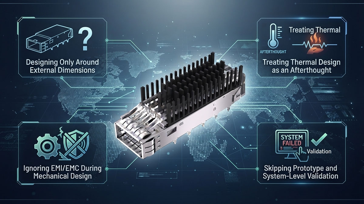
التصميم بناءً على الأبعاد الخارجية فقط
إن التركيز فقط على الأبعاد الخارجية للقفص قد يؤدي إلى تصميم يبدو متوافقًا ظاهريًا ولكنه يفشل أثناء عملية دمج المنصة الفعلية. فالطول والعرض والارتفاع الكلي ليست سوى جزء من الواجهة الميكانيكية.
تشمل الأخطاء الشائعة ما يلي:
- مع تجاهل البصمة الفعلية للوحة الدوائر المطبوعة.
- عدم محاذاة فتحات التثبيت أو ميزات التثبيت.
- تجاهل التداخل مع المكونات المجاورة.
- عدم مراعاة مساحة الفراغ في اللوحة الأمامية.
- إهمال التفاوتات في الأبعاد.
- بافتراض أن الأبعاد الاسمية تضمن التوافق المادي.
يتطلب تصميم قفص بصري مخصص ناجح مساحة داخلية وخارجية كافية، بالإضافة إلى الأبعاد الكلية الصحيحة. وتساعد مراجعة القفص مع لوحة الدوائر المطبوعة، وجهاز الإرسال والاستقبال، والهيكل، والمكونات المحيطة على كشف أي تداخل قبل بدء الإنتاج.
التعامل مع التصميم الحراري كفكرة ثانوية
غالباً ما يُستهان بالتصميم الحراري عند البدء بالتخصيص بناءً على المتطلبات الميكانيكية. قد يتناسب القفص بشكل صحيح ولكنه مع ذلك يُسبب مقاومة حرارية مفرطة أو يُعيق مسار تدفق الهواء المقصود حول أجهزة الإرسال والاستقبال الضوئية.
تشمل الأخطاء الشائعة في التصميم الحراري ما يلي:
- عدم كفاية تلامس المشتت الحراري.
- عدم كفاية التوصيل الحراري بين المكونات.
- هياكل تبديد الحرارة ذات مواقع سيئة.
- سد قنوات تدفق الهواء الموجودة.
- ترك مساحة غير كافية حول مشتتات الحرارة.
- تقييم السلوك الحراري فقط بعد الانتهاء من التصميم الميكانيكي.
ينبغي مراعاة المتطلبات الحرارية في تصميم القفص منذ البداية. وهذا أمر بالغ الأهمية خاصةً بالنسبة للمنصات البصرية عالية الكثافة، حيث يمكن لأجهزة الإرسال والاستقبال المتعددة أن تُركّز الحرارة في حيز محدود.
تجاهل التداخل الكهرومغناطيسي/التوافق الكهرومغناطيسي أثناء التصميم الميكانيكي
قد يتم إغفال اعتبارات التوافق الكهرومغناطيسي (EMI) والتداخل الكهرومغناطيسي (EMC) عند التعامل مع التخصيص بشكل أساسي كمهمة هندسية للأبعاد. ومع ذلك، فإن هندسة القفص، وموصلات التأريض، وهياكل الحماية، وواجهات الهيكل، كلها عوامل تؤثر على الأداء الكهرومغناطيسي.
تشمل الأخطاء المحتملة ما يلي:
- حماية غير مكتملة حول المنافذ البصرية.
- ضعف التأريض بين القفص والهيكل.
- وضع غير صحيح لأصابع الزنبرك.
- فجوات مفرطة بين الهياكل الموصلة.
- ضغط التلامس غير كافٍ.
- عدم مراعاة استمرارية الحماية بين الأقفاص المتجاورة.
توضح هذه المشكلات سبب ضرورة تحديد متطلبات التوافق الكهرومغناطيسي قبل وضع التصميم النهائي للقفص. يجب أن تعمل التفاوتات الميكانيكية وخصائص التلامس الكهربائي معًا للحفاظ على حماية وتأريض موثوقين في ظل ظروف التشغيل المقصودة.
تجاوز مرحلة النموذج الأولي والتحقق على مستوى النظام
لا يضمن نموذج التصميم بمساعدة الحاسوب (CAD) الذي يبدو صحيحًا بالضرورة نجاح دمجه في الواقع العملي. فإهمال التحقق من صحة النموذج الأولي قد يسمح ببقاء التداخلات الميكانيكية أو القيود الحرارية أو مشاكل الوصول غير مكتشفة حتى مرحلة الإنتاج أو النشر.
ينبغي أن تتحقق عملية التحقق المناسبة مما يلي:
- تركيب القفص المادي على لوحة الدوائر المطبوعة المستهدفة والهيكل.
- إدخال واستخراج جهاز الإرسال والاستقبال الضوئي.
- محاذاة المنافذ مع اللوحة الأمامية.
- مسافة فاصلة عن المكونات المجاورة.
- تحديد موضع المشتت الحراري والوصلة الحرارية.
- تدفق الهواء حول الواجهة البصرية.
- تأريض وحماية الاتصال.
- الاستقرار الميكانيكي أثناء عمليات الخدمة المتكررة.
لذا، يُعد اختبار النماذج الأولية جزءًا مهمًا من تخصيص القفص البصري. فهو يتيح فرصة لتحسين الأبعاد، وخصائص التركيب، والهياكل الحرارية، وعناصر الحماية قبل أن يصبح التصميم جاهزًا للإنتاج.
☑️ كيف يتم تقييم قفص بصري مخصص قبل نشره؟
ينبغي تقييم قفص بصري مُصمّم خصيصًا وفقًا للمنصة الكاملة، وليس بناءً على توافق أبعاده فقط. قبل التركيب، يجب على المهندسين التحقق من التوافق الميكانيكي، وسهولة الوصول إلى جهاز الإرسال والاستقبال، والسلوك الحراري، وتدفق الهواء، وخصائص التداخل الكهرومغناطيسي، واتساق التصنيع، لضمان أداء القفص بكفاءة في بيئته المُخصصة.
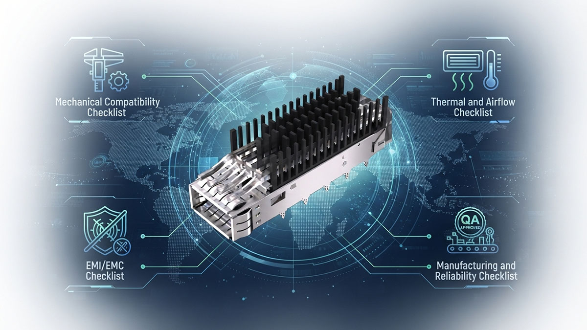
قائمة التحقق من التوافق الميكانيكي
يجب التأكد من التوافق الميكانيكي أولاً، إذ يجب أن يتوافق الهيكل الخارجي تمامًا مع لوحة الدوائر المطبوعة، والهيكل، واللوحة الأمامية، وجهاز الإرسال والاستقبال الضوئي. قد يتسبب الهيكل الخارجي الذي لا يفي بمعايير التكامل الميكانيكي الأساسية في مشاكل أثناء التركيب، حتى وإن كانت خصائصه الأخرى مقبولة.
تشمل الفحوصات الرئيسية ما يلي:
- تحقق من الأبعاد الكلية للقفص ومساحة لوحة الدوائر المطبوعة.
- تأكد من محاذاة فتحة التثبيت والدبوس واللسان وآلية التثبيت.
- تحقق من موضع المنافذ الضوئية بالنسبة لفتحات اللوحة الأمامية.
- افحص المسافة بين لوحة الدوائر المطبوعة المجاورة ومكونات الهيكل.
- تحقق من سهولة إدخال جهاز الإرسال والاستقبال وإخراجه.
- تأكد من أن ألسنة السحب والمزالج ومناطق الوصول للخدمة لا تزال قابلة للوصول.
ينبغي إجراء هذه الفحوصات باستخدام المكونات المتوافقة الفعلية كلما أمكن ذلك. يساعد هذا في تحديد التداخلات المتعلقة بالتفاوتات التي قد لا تكون واضحة من الأبعاد الاسمية في التصميم بمساعدة الحاسوب.
قائمة التحقق من الحرارة وتدفق الهواء
يُحدد التحقق الحراري ما إذا كان القفص المُصمم خصيصًا وهياكل تبديد الحرارة المرتبطة به قادرة على العمل بكفاءة في ظل ظروف نموذجية. ولا يُعد التوافق الميكانيكي وحده كافيًا للتأكد من أن الواجهة البصرية تتمتع بتبريد مناسب.
ينبغي أن يشمل التقييم ما يلي:
- تلامس المشتت الحراري مع السطح الحراري المقصود.
- تحديد موضع مادة التوصيل الحراري وتناسقها.
- اتجاه تدفق الهواء عبر القفص والمجموعة المحيطة به.
- القيود المحتملة على تدفق الهواء الناتجة عن هندسة القفص.
- سلوك درجة الحرارة تحت أحمال نموذجية للوحدة البصرية.
- النقاط الساخنة المحتملة حول المنافذ الضوئية ذات الكثافة السكانية العالية.
ينبغي تقييم النتائج في ظل ظروف تعكس التكوين الفعلي للمنصة. وهذا أمر بالغ الأهمية خاصةً بالنسبة لشبكات SFP28 وQSFP عالية الكثافة، وعمليات النشر الضوئية عالية السرعة، حيث يمكن أن يؤثر انخفاض تدفق الهواء بشكل أكبر على الأداء الحراري.
قائمة التحقق من التوافق الكهرومغناطيسي
يجب أن يؤكد تقييم التوافق الكهرومغناطيسي أن القفص المُصمم خصيصًا يوفر الحماية والتأريض المطلوبين عند دمجه مع النظام الكامل. لا ينبغي تقييم القفص بمعزل عن لوحة الدوائر المطبوعة والهيكل، لأن التوصيل الكهربائي واستمرارية الحماية يعتمدان على علاقتهما الفيزيائية.
تشمل الفحوصات المهمة ما يلي:
- تحقق من استمرارية الحماية حول الواجهة البصرية.
- افحص نقاط التأريض ومواقعها.
- تأكد من وجود اتصال كهربائي موثوق بين القفص والهيكل عند الحاجة.
- تحقق من مسارات التسرب الكهرومغناطيسي المحتملة.
- قم بتقييم مدى ترابط أصابع الزنبرك وثبات الاتصال.
- تأكد من متطلبات التوافق الكهرومغناطيسي (EMC) المعمول بها على مستوى المنصة.
ينبغي أيضًا مراعاة التفاوتات الميكانيكية أثناء هذا التقييم. قد يصبح التلامس الأرضي الذي يعمل بأبعاده الاسمية غير موثوق به إذا أدى تراكم التفاوتات إلى تقليل فعالية التلامس.
قائمة التحقق من التصنيع والموثوقية
تضمن عملية التحقق من صحة التصنيع أن القفص البصري المصمم خصيصًا قادر على إعادة إنتاج التصميم المعتمد باستمرار، بدلاً من أن يعمل بشكل صحيح كنموذج أولي فقط. وهذا أمر بالغ الأهمية، خاصةً عندما يحتوي القفص على العديد من الوصلات الميكانيكية ذات التفاوتات الدقيقة.
ينبغي أن يأخذ التقييم النهائي في الاعتبار ما يلي:
- اتساق التفاوتات البُعدية.
- اتساق المواد والتشطيب السطحي.
- موثوقية التركيب والتثبيت.
- إدخال وإخراج جهاز الإرسال والاستقبال بشكل متكرر.
- الاستقرار الهيكلي أثناء الصيانة الروتينية.
- التوافق بين النموذج الأولي وتجميعات الإنتاج.
لذا، ينبغي أن يستند قرار النشر الناجح إلى كلٍ من الأداء الهندسي وقابلية تكرار التصنيع. فعند التحقق من الملاءمة الميكانيكية، والسلوك الحراري، وأداء التوافق الكهرومغناطيسي، واتساق الإنتاج، يصبح القفص البصري المُصمم خصيصًا في وضع أفضل بكثير لضمان التكامل الموثوق مع منصة الشبكات المستهدفة.
☑️ كيفية العمل مع LINK-PP هل تبحث عن حلول مخصصة لأقفاص بصرية؟
العمل مع LINK-PP يبدأ تصميم حلول الأقفاص البصرية المخصصة بتحديد المنصة المستهدفة وقيودها بدقة. إن توفير معلومات دقيقة حول الجوانب الميكانيكية والبصرية والحرارية والتوافق الكهرومغناطيسي في وقت مبكر يُمكّن فريق التخصيص من ترجمة متطلبات التطبيق إلى مواصفات قفص قابلة للقياس، مما يقلل من عدم اليقين في عملية التكامل.
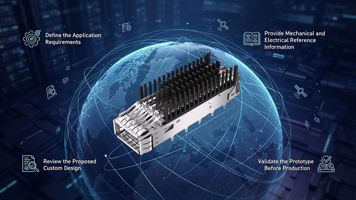
تحديد متطلبات التطبيق
تتمثل الخطوة الأولى في تحديد ما يجب أن يحققه القفص البصري المُصمم خصيصاً ضمن الجهاز المستهدف. ينبغي أن تصف المتطلبات كلاً من الواجهة البصرية والبيئة المادية التي سيعمل فيها القفص.
تتضمن المعلومات الرئيسية ما يلي:
- نوع وشكل جهاز الإرسال والاستقبال الضوئي.
- عدد المنافذ الضوئية المطلوبة.
- أبعاد لوحة الدوائر المطبوعة ومنطقة التركيب المتاحة.
- قيود الهيكل واللوحة الأمامية.
- المسافة المطلوبة بين المنافذ وإمكانية الوصول إليها.
- متطلبات تبديد الحرارة وتدفق الهواء.
- متطلبات التوافق الكهرومغناطيسي والتأريض.
- شروط إدخال جهاز الإرسال والاستقبال واستخراجه وصيانته.
تساعد المتطلبات المحددة بوضوح على التمييز بين قيود التصميم الأساسية والتفضيلات الاختيارية. وهذا يوفر لفريق التخصيص أساسًا عمليًا لتطوير تكوين قفص مناسب.
توفير معلومات مرجعية ميكانيكية وكهربائية
تتيح المعلومات المرجعية مطابقة تصميم القفص مع المنصة الفعلية بدلاً من تقديره بناءً على أبعاد عامة. وكلما كانت البيانات المرجعية أكثر اكتمالاً، كان من الأسهل تحديد التداخلات المحتملة وقيود التداخل أثناء مرحلة التصميم.
قد تتضمن المعلومات المرجعية المفيدة ما يلي:
- رسومات لوحة الدوائر المطبوعة أو المواصفات الأبعادية.
- رسومات اللوحة الأمامية وأبعاد الفتحة.
- مراجع القفص أو الموصل الموجودة.
- أبعاد جهاز الإرسال والاستقبال الضوئي.
- مواقع فتحات التثبيت والتثبيت.
- المساحة المطلوبة حول المكونات المجاورة.
- المتطلبات الكهربائية أو متطلبات التأريض أو متطلبات التوافق الكهرومغناطيسي ذات الصلة.
بالنسبة للمنصات المتخصصة، تعتبر الرسومات الميكانيكية الموجودة مفيدة بشكل خاص لأنها تكشف عن العلاقات بين القفص البصري والهياكل المحيطة التي قد لا تكون واضحة من أبعاد القفص وحدها.
مراجعة التصميم المخصص المقترح
بعد تحديد المتطلبات والمعلومات المرجعية، ينبغي مراجعة تصميم القفص المقترح مقارنةً بالمنصة المستهدفة قبل البدء في مرحلة النموذج الأولي. تتيح هذه المرحلة فرصةً لتحديد أي تعارضات في حين أن التغييرات التصميمية لا تزال قابلةً للإدارة نسبيًا.
ينبغي أن يركز التقييم على ما يلي:
- الأبعاد الكلية للقفص ومساحة لوحة الدوائر المطبوعة.
- محاذاة المنافذ والتباعد بينها.
- ميزات التركيب والتثبيت.
- مشتتات الحرارة والهياكل الحرارية.
- مساحة تدفق الهواء.
- ميزات الحماية والتأريض.
- الوصول إلى مدخل ومخرج جهاز الإرسال والاستقبال.
تساعد مراجعة التصميم التفصيلية على ضمان مراعاة المتطلبات الميكانيكية والحرارية ومتطلبات التوافق الكهرومغناطيسي معًا. كما أنها تقلل من احتمالية أن يؤدي تغيير أحد العناصر إلى مشكلة غير مقصودة في مكان آخر من التجميع.
التحقق من صحة النموذج الأولي قبل الإنتاج
يُعدّ التحقق من صحة النموذج الأولي آخر مرحلة هندسية قبل الانتقال إلى مرحلة الإنتاج. يجب تقييم النموذج الأولي باستخدام مكونات المنصة الفعلية أو مكونات مماثلة، وذلك لضمان تقييم التصميم في ظل ظروف تكامل واقعية.
قد تتضمن عملية التحقق ما يلي:
- اختبار التوافق الميكانيكي — تأكد من أن القفص يتماشى بشكل صحيح مع لوحة الدوائر المطبوعة والهيكل واللوحة الأمامية.
- اختبار توافق جهاز الإرسال والاستقبال — التحقق من الإدخال والاستخراج والاحتفاظ وإمكانية الوصول.
- التحقق الحراري — تحقق من تلامس المشتت الحراري، وتدفق الهواء، وسلوك درجة الحرارة.
- التحقق من التوافق الكهرومغناطيسي (EMI/EMC) — تقييم أداء الحماية والتأريض عند الاقتضاء.
- تأكيد التصميم النهائي — تسجيل الأبعاد المعتمدة، والتفاوتات المسموح بها، والمواد، والخصائص الهيكلية للإنتاج.
بمجرد إتمام هذه الفحوصات، يُصبح النموذج الأولي المُعتمد مرجعًا لتكوين الإنتاج. تُساعد آلية العمل هذه، القائمة على المتطلبات، في تحويل طلب قفص بصري مُتخصص إلى حل قابل للتكرار ومتوافق مع منصة الشبكات الفعلية.
☑️ الخاتمة
يمكن أن يكون القفص البصري القياسي الجاهز حلاً فعالاً عندما تتوافق أبعاده وترتيب منافذه وخصائصه الحرارية وميزات الحماية من التداخل الكهرومغناطيسي مع المنصة المضيفة. مع ذلك، قد تتطلب معدات الشبكات المتخصصة أكثر مما توفره المواصفات القياسية. وتُعدّ تعارضات الأبعاد، والتصميمات عالية الكثافة، والقيود الحرارية، ومتطلبات الحماية، وهياكل التركيب الفريدة، مؤشرات قوية على ضرورة النظر في تخصيص القفص البصري.
الاعتبارات الرئيسية هي:
- قم بمطابقة هندسة القفص وهيكل التثبيت مع لوحة الدوائر المطبوعة والهيكل الفعليين.
- تحسين كثافة المنافذ، والتباعد بينها، وسهولة الوصول إلى جهاز الإرسال والاستقبال.
- قم بدمج متطلبات تبديد الحرارة وتدفق الهواء في تصميم القفص.
- يجب مراعاة الحماية من التداخل الكهرومغناطيسي والتأريض خلال مرحلة التصميم.
- تحقق من الملاءمة الميكانيكية والسلوك الحراري والموثوقية قبل النشر.
- استخدم اختبار النماذج الأولية لتحسين القفص المخصص قبل الإنتاج.
في نهاية المطاف، تكتسب الأقفاص البصرية المصممة خصيصًا قيمتها القصوى عندما تحل تحديًا محددًا في التكامل، بدلاً من مجرد توفير شكل غير قياسي. ومن خلال الجمع بين متطلبات التطبيق والتصميم الميكانيكي والإدارة الحرارية واعتبارات التداخل الكهرومغناطيسي والتحقق من صحة النموذج الأولي، LINK-PPيُمكن لفريق التخصيص التابع لنا مساعدتك في تطوير تجميعات الأقفاص المُناسبة لمنصات الشبكات الضوئية المُتخصصة. للحصول على حلول الاتصال الضوئي ودعم إضافي للتخصيص، تفضل بزيارة LINK-PP المتجر الرسمي لاستكشاف الخيارات المتاحة وربط متطلبات منصتك بالحل المناسب.