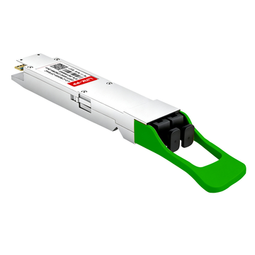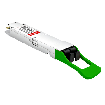
Are your data center networks struggling to keep up with the surging bandwidth demands of modern AI and machine learning workloads? As hyperscale fabrics scale rapidly, the MMS4X50-NM 800G OSFP 2xFR4 optical transceiver delivers the high-density performance required to eliminate critical interconnect bottlenecks. By packing dual independent 400G optical engines into a single compact module, it doubles throughput without consuming extra switch front-panel space.
How can engineering teams achieve this 800G leap across data halls without replacing their existing duplex single-mode fiber infrastructure? While parallel MPO-based optics often introduce severe cabling congestion and high deployment costs, CWDM4 multiplexing resolves this by splitting the 800G signal across two duplex LC links (four fibers total). This approach provides a practical, cost-effective path to scale leaf-spine and backend fabrics directly over standard Dual LC connections.
✴️ Overview and Architecture of the MMS4X50-NM 800G OSFP Transceiver
Next-generation hyperscale data centers require high-density optical interfaces capable of keeping pace with massive throughput demands. The MMS4X50-NM addresses this requirement by integrating dual optical engines into a high-thermal-efficiency OSFP package. This architecture optimizes switch front-panel space while delivering deterministic 800Gbps aggregate bandwidth for demanding cloud infrastructure.

Defining the 800G OSFP Form Factor and Twin-Port Architecture
The MMS4X50-NM leverages the Octal Small Form-Factor Pluggable (OSFP) standard, which provides the electrical integrity and thermal headroom required for 800G line rates. Its physical design features integrated cooling fins and an 8-lane electrical host interface operating at 100Gbps PAM4 per lane.
Built around a twin-port concept, the module groups these eight electrical lanes into two completely distinct 400G channels. This allows a single 800G OSFP cage to function either as a monolithic 800G link or as two independent 400G interfaces, effectively doubling port density without altering mechanical footprints.
How Dual Independent 400G-FR4 Optical Engines Work in One Transceiver
Inside the MMS4X50-NM, two separate 400G-FR4 optical engines operate side by side, each powered by dedicated CWDM EML lasers and internal multiplexers. Each engine aggregates four 100G PAM4 optical wavelengths onto one transmit fiber per engine (paired with a separate receive fiber), while the internal demultiplexer separates them at the receiver.
An advanced onboard Digital Signal Processor (DSP) retimes and reshapes the incoming host electrical signals independently for each engine. Because the optical sub-assemblies operate autonomously, a disruption or link-state transition on one 400G-FR4 path does not impact the transmission performance or telemetry of the other.
Essential Role of 2xFR4 in High-Bandwidth AI Backend Fabrics
Modern AI and machine learning clusters depend heavily on lossless, non-blocking interconnects to prevent GPU starvation during large-scale model training. The MMS4X50-NM 2xFR4 design supports high-radix leaf-spine switching fabrics by providing direct, low-latency optical paths across spans up to 2km.
Deploying dual 400G-FR4 engines within a single module simplifies physical cabling across backend accelerator pods. It enables high-density switch-to-switch and switch-to-leaf interconnects over standard duplex single-mode fiber, minimizing cable bundle bulk and maximizing airflow in dense compute halls.
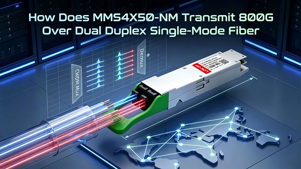
✴️ How Does MMS4X50-NM Transmit 800G Over Dual Duplex Single-Mode Fiber
Transmitting 800G across extended data hall distances requires combining high-speed electrical conversion with optical multiplexing. The MMS4X50-NM achieves this by converting host PAM4 signals into dual multiplexed optical streams designed for standard single-mode fiber infrastructure.
Electrical 8x100G PAM4 Host Interface and DSP Retimer Architecture
The MMS4X50-NM interfaces with the host switch via an 8-lane electrical bus, where each lane carries a 53.125GBd PAM4 signal to deliver 100Gbps. A high-performance DSP retimer receives these incoming signals to equalize electrical channel loss, suppress jitter, and perform clock and data recovery (CDR).
After retiming, the DSP conditions the clean 8x100G PAM4 data streams and routes them directly to the optical driver circuitry across both 400G engines. This process ensures low pre-FEC bit error rates and maintains pristine signal integrity before electro-optical modulation occurs.
CWDM4 Wavelength Grid (1271–1331nm) and Multiplexing Explained
To transmit 400G per engine over a single transmit fiber, the MMS4X50-NM utilizes the CWDM4 wavelength grid with 20nm channel spacing at 1271, 1291, 1311, and 1331nm. Each optical lane is driven by a high-speed Electro-absorption Modulated Laser (EML), which provides superior chirp control and high extinction ratios for 100G PAM4 signals.
An integrated optical multiplexer combines all four EML wavelengths onto a single fiber core. On the receiving end, an optical demultiplexer separates the incoming wavelengths and directs them onto high-speed photodetectors paired with low-noise Transimpedance Amplifiers (TIAs) to reconstruct the electrical waveforms.
Dual LC Duplex (4-Fiber SMF) Optical Interface Layout
Unlike parallel optical modules that rely on multi-fiber ribbon connectors, the MMS4X50-NM features dual LC duplex connectors. This physical layout accommodates two completely independent 400G FR4 links, utilizing a total of only four standard single-mode fibers (two Tx and two Rx).
This 4-fiber design allows network operators to reuse existing structured duplex LC patch panels without costly fiber plant overhauls. Furthermore, it significantly reduces cable bulk at the switch faceplate, improving chassis ventilation and simplifying high-density rack management.
Optical Power Margins and Dispersion Management for 2km Reach
Over a 2km span of standard G.652 single-mode fiber, chromatic dispersion can distort high-baud-rate PAM4 eye diagrams. The MMS4X50-NM minimizes these dispersion penalties by pairing CWDM wavelengths operating near the zero-dispersion window with stable, narrow-linewidth EML lasers.
Combined with the high sensitivity of the integrated TIAs, the module maintains a robust optical link budget that easily accommodates fiber attenuation and patch panel insertion losses. This delivers deterministic link margins and error-free transmission across multi-tier enterprise and hyperscale data center spans.
✴️ Comparing MMS4X50-NM Against 800G OSFP 2xDR4 Optical Solutions
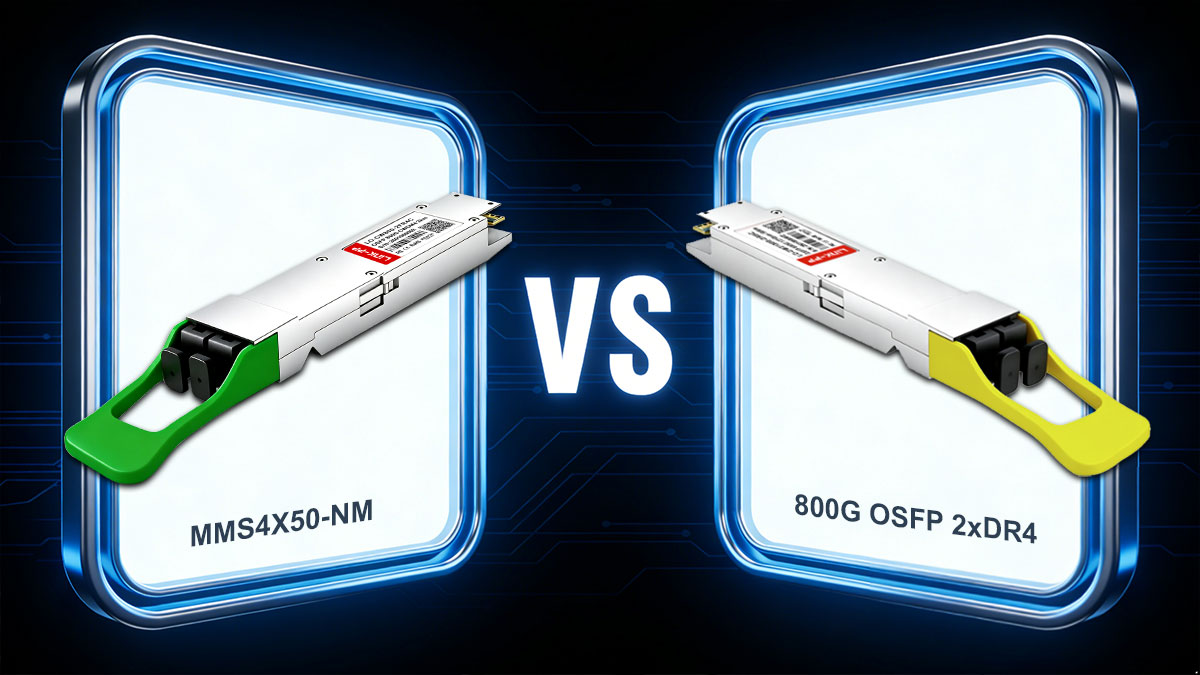
Selecting the optimal 800G optical architecture requires balancing reach, connector reliability, and structured cabling investments. While parallel single-mode optics suit short-reach breakout scenarios, the MMS4X50-NM provides a streamlined alternative for longer spans across data hall suites. Evaluating their core architectural differences illustrates how multiplexing reduces fiber strand consumption from 16 to just 4 per 800G link, solving high-density cabling constraints.
The following table highlights the primary technical and operational differences between the MMS4X50-NM and standard 800G 2xDR4 optical solutions:
| Parameter / Feature | MMS4X50-NM (800G OSFP 2xFR4) | Standard 800G OSFP 2xDR4 |
| Optical Architecture | Wavelength Division Multiplexing | Parallel Single-Mode |
| Optical Interface | Dual LC Duplex | Dual MPO-12/APC |
| Standard Reach | Up to 2km over SMF | Up to 500m over SMF |
| Cabling Infrastructure | Reuses standard Duplex LC fiber plant | Requires dedicated high-count MPO trunks |
| Connector Sensitivity | Lower dust/particle surface contamination risk | Higher risk of multi-fiber ferrule misalignment |
| Primary Deployment | Spine-leaf uplinks & long-span AI backends | Short-reach top-of-rack & GPU breakouts |
Wavelength Division Multiplexing vs. Parallel Single-Mode
The MMS4X50-NM operates on Wavelength Division Multiplexing (CWDM), multiplexing four separate optical lanes onto a single fiber core per direction for each 400G engine. In contrast, 800G 2xDR4 uses Parallel Single-Mode (PSM) technology, which transmits a single unmultiplexed 1310nm wavelength across dedicated parallel optical strands.
This difference gives the MMS4X50-NM a decisive advantage in reach and signal integrity over longer spans. By utilizing EML lasers across the CWDM4 grid, the 2xFR4 transceiver comfortably achieves 2km links, far exceeding the typical 500m limitation inherent to 2xDR4 parallel optics.
Cabling Infrastructure: 4-Fiber Dual LC vs. 16-Fiber MPO/MTP Trunks
Physical layer density is heavily impacted by connector choice and fiber strand consumption. The MMS4X50-NM requires only four optical fibers terminated with dual standard duplex LC connectors, simplifying cable pathways and reducing patch panel footprint.
Conversely, 800G 2xDR4 deployments require 16 optical fibers across dual MPO trunks, creating dense cable congestion in overhead trays and vertical rack managers. The 4-fiber LC approach of the MMS4X50-NM eliminates the complexity of MPO polarity alignment and substantially lowers optical surface contamination risks.
CAPEX & OPEX Trade-offs: Transceiver Unit Cost vs. Fiber Plant Density
While 2xDR4 optical modules often have lower initial component costs due to simpler single-wavelength lasers, they shift significant CAPEX onto structured fiber infrastructure. Outfitting an entire data center with high-density multi-fiber MPO trunks and patch panels significantly drives up day-one installation expenses.
The MMS4X50-NM delivers superior long-term OPEX and lifecycle value by reusing existing duplex single-mode fiber plants. Network operators avoid costly structured cabling retrofits while enjoying lower installation labor, streamlined cable tracking, and reduced physical footprint per rack.
✴️ Network Topology and Breakout Use Cases for MMS4X50-NM Module
Modern data center architectures demand flexible physical layer solutions that adapt seamlessly to both high-radix monolithic fabrics and distributed breakout topologies. The MMS4X50-NM provides this versatility across four key deployment scenarios: direct 800G spine interconnects, 2x400G breakout to legacy leaves, brownfield upgrades over existing LC plants, and AI-scale backend fabrics.
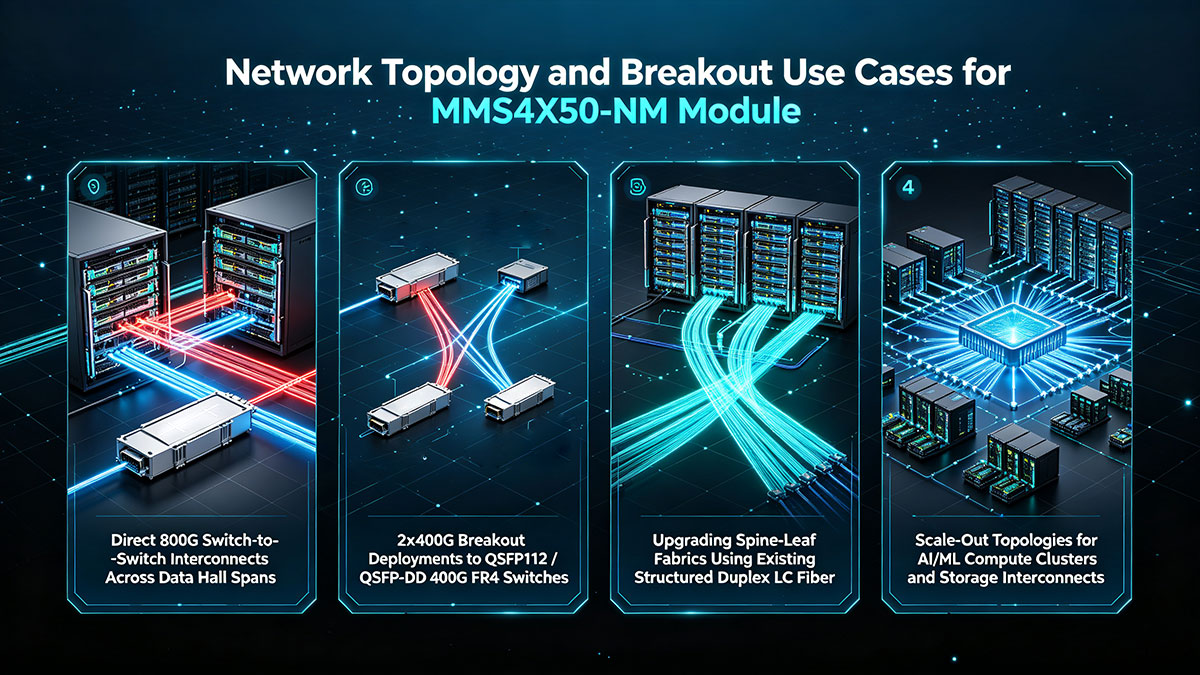
Direct 800G Switch-to-Switch Interconnects Across Data Hall Spans
In core spine and super-spine layers, the MMS4X50-NM establishes high-capacity 800G point-to-point connections between dense aggregation switches across distances up to 2km. The transceiver pairs two 400G-FR4 links in tandem to transport a full 800Gbps payload over two standard single-mode fiber pairs.
This configuration delivers non-blocking interconnectivity across expansive data hall suites without requiring intermediary optical amplification or dispersion compensation hardware. Network architects can expand core backbone bandwidth while keeping switch port consumption and front-panel cabling strictly contained.
2x400G Breakout Deployments to QSFP112 / QSFP-DD 400G-FR4 Switches
Configuring the host switch port into a 2x400G split mode enables the MMS4X50-NM to act as an optical breakout hub connecting 800G OSFP spines directly to 400G leaf switches. Because each optical engine operates independently, each duplex LC interface links natively to a standard 400GBASE-FR4 transceiver packaged in either QSFP112 or QSFP-DD form factors.
This design eliminates the need for bulky optical breakout harnesses or MPO-to-LC conversion cassettes. Network teams gain a clean, direct point-to-point optical link between dissimilar switch generations, simplifying tiered migration without stranding expensive port capacity.
Upgrading Spine-Leaf Fabrics Using Existing Structured Duplex LC Fiber
Migrating traditional enterprise and cloud data centers to 800G speeds often stalls due to the massive cost of replacing legacy single-mode cabling. Deploying the MMS4X50-NM circumvents this infrastructure barrier by operating directly over existing structured duplex LC fiber runs.
Facilities can double or quadruple fabric throughput without replacing existing cross-connect patch panels or pulling new multi-fiber trunk cables. This strategy protects legacy fiber investments, drastically cuts deployment timelines, and simplifies day-two optical maintenance.
Scale-Out Topologies for AI/ML Compute Clusters and Storage Interconnects
Distributed training workloads rely on ultra-low-latency backend fabrics to synchronize billions of model parameters across accelerated server nodes. The MMS4X50-NM connects high-density rail-optimized leaf switches to spine tiers, ensuring deterministic, jitter-free data delivery across extensive GPU compute fabrics.
Additionally, the transceiver provides robust, high-bandwidth interconnects for all-flash NVMe-oF storage arrays serving massive AI training datasets. Its 2km reach allows storage pods and compute clusters to be placed in separate halls or floors without sacrificing throughput or inducing packet drops.
✴️ What Key Optical Metrics Define the MMS4X50-NM Link Budget
Deploying reliable 800G links across data hall spans requires maintaining a disciplined optical power budget to avoid frame loss and signal degradation. The MMS4X50-NM adheres to rigorous transmitter quality thresholds and receiver sensitivity limits to guarantee robust end-to-end performance over single-mode fiber.
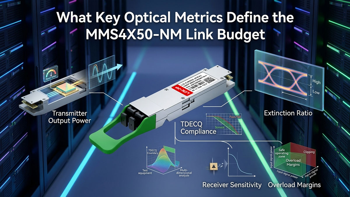
Transmitter Output Power, Extinction Ratio, and TDECQ Compliance
Transmitter optical health directly dictates how cleanly a 100G PAM4 modulated waveform travels through single-mode fiber. The MMS4X50-NM leverages high-linearity EML lasers to maintain high optical launch power and superior eye opening across all CWDM channels.
Key transmit parameters determine the baseline optical signal quality before entering the fiber plant:
- Launch Power (OMA): Maintains sufficient optical power per lane between -0.5dBm and +4.0dBm.
- Extinction Ratio (ER): Enforces a minimum 3.5dB threshold for clean PAM4 logic separation.
- TDECQ Limit: Complies with the ≤3.4dB requirement to ensure low transmitter distortion.
- Wavelength Stability: Anchors each lane precisely within the 20nm CWDM4 grid tolerance.
Receiver Sensitivity, Overload Margins, and G.652 Fiber Attenuation
At the receiving end, the internal transimpedance amplifier (TIA) array must reliably detect weakened PAM4 optical signals without distortion. The MMS4X50-NM provides a sensitive receiver threshold alongside adequate overload protection to prevent photodetector saturation on short patch cables.
Standard G.652 single-mode fiber introduces roughly 0.4dB/km attenuation in the 1310nm CWDM window, totaling under 1.0dB across a 2km span. Because the transceiver receiver sensitivity threshold extends down to around -7dBm (OMA outer), operators retain ample optical power margin against fiber absorption and chromatic dispersion.
IEEE KP4 Pre-FEC Bit Error Rate and Margin Analysis
Because 100G PAM4 signals operate with reduced multi-level voltage spacing, error correction is mandatory to achieve flawless data transmission. The MMS4X50-NM relies on IEEE 802.3ck KP4 Forward Error Correction (RS(544,514)) processed by the host switch and DSP to eliminate transmission errors.
Maintaining a healthy link requires understanding the baseline metrics that govern physical layer integrity:
- Pre-FEC Threshold: Enforces a raw bit error rate strictly below the 2.4 × 10⁻⁴ correction limit.
- Post-FEC Target: Guarantees zero frame loss by driving the corrected BER down to 1 × 10⁻¹⁵.
- SNR Margin: Provides sufficient signal-to-noise headroom to absorb laser aging and thermal drift.
- DSP Equalization: Automatically compensates for high-frequency electrical loss across the host PCB.
Managing Insertion Loss Across Multi-Tier Patch Panels
Structured data center cabling frequently passes through multiple Main Cross-Connect (MCX) and Intermediate Cross-Connect (ICX) bulkheads. With the MMS4X50-NM compliant with a total channel insertion loss budget of approximately 4.0dB for 2km FR4 links (including both fiber attenuation and connector losses), connector loss allocation must be managed carefully.
Each standard LC-to-LC mating adapter typically contributes 0.2dB to 0.5dB of insertion loss depending on polish quality. Deploying high-grade, low-loss LC patch panels ensures that multi-tier cross-connects remain well within the 4.0dB envelope, preventing uncorrectable FEC bursts and intermittent packet drops.
✴️ Deployment Best Practices and Thermal Guidelines for MMS4X50-NM
Deploying high-density 800G optical transceivers requires strict adherence to physical installation standards and proactive thermal management. Following proper handling procedures for the MMS4X50-NM ensures sustained physical-layer integrity and prevents premature hardware degradation in mission-critical fabrics.

OSFP Finned Top Handling, Thermal Pad Contact, and Mechanical Latching
The MMS4X50-NM features an integrated finned top design that interfaces directly with switch airflow channels to conduct heat away from the internal DSP. Technicians must avoid applying uneven downward force on the heatsink fins during insertion to prevent damaging internal thermal interface materials.
Proper insertion requires fully engaging the module until the mechanical latch clicks into the OSFP cage to ensure flush thermal pad contact. Inspect the pull-tab release mechanism before installation to avoid mechanical binding or port misalignment inside dense chassis line cards.
End-Face Cleaning Standards for Dual LC to Prevent High-Density Burn-in
High-power PAM4 EML optical engines concentrate intense light energy onto tiny single-mode fiber core surfaces. Any microscopic dust, oil, or debris trapped on the Dual LC connector face can lead to localized laser burn-in and irreversible ferrule pitting.
Installers should implement IEC 61300-3-35 inspection standards and clean every LC connector with dedicated dry-cleaning pens before insertion. Always cap unused optical ports immediately with dust covers to protect internal optical multiplexers and TIA receivers from airborne contamination.
Managing TX/RX Polarity and Channel Alignment in Breakout Links
The MMS4X50-NM utilizes a dual-engine architecture where two separate Duplex LC ports map to specific 400G logical interfaces. Maintaining standard fiber crossover (Tx-Rx alignment) across structured patch panels is critical to ensure transmitter outputs align correctly with opposite receiver inputs.
When breaking out to 400G FR4 modules, clearly label each LC pair at both ends to prevent cross-connecting Engine 0 and Engine 1 paths. Misaligned fiber pairs will cause link state flapping, improper clock recovery, and false optical loss-of-signal alarms on the switch operating system.
Managing 14 - 16W Power Dissipation in Dense 64-Port 800G Chassis
A fully loaded 64-port 800G OSFP switch chassis can generate nearly 1kW of thermal load from optical transceivers alone, as each MMS4X50-NM dissipates roughly 14 to 16W under full traffic. Facility engineers must maintain unrestricted front-to-back chassis airflow and ensure rack fans operate at adequate static pressure.
Monitor real-time module internal temperature sensors to verify operating levels remain below the maximum 70°C commercial case temperature limit as defined in the OSFP MSA. Populating empty switch cages with OSFP airflow filler blanks prevents bypass air recirculation and ensures uniform cooling across active optical modules.
✴️ How to Monitor and Troubleshoot MMS4X50-NM Optical Links
Maintaining uninterrupted 800G fabric throughput requires proactive telemetry monitoring and systematic physical layer troubleshooting. By leveraging switch-level diagnostic tools, engineers can quickly isolate signal anomalies and optimize the performance of the MMS4X50-NM across complex optical paths.

Reading Digital Diagnostic Monitoring Telemetry for Tx and Rx Power
The MMS4X50-NM embeds comprehensive Digital Diagnostic Monitoring (DDM) capabilities conforming to CMIS standards to report real-time operating metrics. Because the transceiver houses dual independent 400G engines, telemetry is monitored separately across all eight optical lanes.
Reviewing these diagnostic parameters via the switch command line reveals critical physical health indicators:
- Lane-by-Lane Power: Check individual Tx and Rx optical power levels against acceptable operating thresholds.
- Laser Bias Current: Monitor current draw to detect degrading laser diodes before failure.
- Internal Temperature: Track case thermal readings to verify heatsink and airflow efficiency.
- Supply Voltage: Confirm steady 3.3V power delivery from the host switch line card.
Identifying Bad Fiber Connections through High Pre-FEC Error Rates
Pre-FEC Bit Error Rate (BER) analysis provides the most reliable early indicator of dirty connectors, micro-bends, or excessive patch panel attenuation. Monitoring per-lane pre-FEC error trends allows operators to identify deteriorating physical paths long before uncorrectable FEC errors cause frame drops.
A significant BER spike localized to one 400G engine typically indicates physical issues on that specific Duplex LC fiber pair rather than an electrical bus failure. Inspect and clean the corresponding LC ferrule immediately using a fiber scope if pre-FEC rates climb near the IEEE-defined 2.4 × 10⁻⁴ KP4 correction limit.
Handling Common Link Flaps and Optical Signal Loss Issues
Intermittent link flaps on the MMS4X50-NM are commonly caused by fiber polarity mismatches, seated connector strain, or marginal optical power budgets. Isolating the issue requires systematic fault domain verification across both hardware and optical cabling:
- Check Loss of Signal (LOS): Verify whether the switch port triggers optical Rx LOS on Engine 0 or Engine 1.
- Swap Patch Cables: Test with a known-good LC-to-LC jumper to rule out internal fiber core breaks, and inspect both ends with a fiber scope before reconnecting.
- Inspect OSFP Seating: Re-seat the transceiver module to ensure flush contact with host cage thermal pads.
- Verify Transceiver Firmware: Ensure the switch OS supports the CMIS revision running on the module.
Verifying Port Configuration and Speed Negotiation via Switch CLI
Before troubleshooting optical hardware, verify that the host switch port profile matches the intended operational mode of the MMS4X50-NM. The switch operating system must be explicitly configured for either native 800G mode or split 2x400G breakout mode to ensure correct SerDes lane mapping.
Use standard CLI interface commands (such as show interfaces transceiver or show interfaces ethernet detail) to confirm lane speed, FEC state, and auto-negotiation status. Mismatched FEC configurations between the 800G OSFP host and downstream 400G-FR4 leaf switches will prevent link training and keep the interface down.
✴️ Final Considerations on Upgrading to MMS4X50-NM 800G OSFP 2xFR4 Interconnects

Transitioning to 800G connectivity is a crucial step for scaling data centers and accelerating AI workloads. The MMS4X50-NM provides a practical upgrade path by delivering 800G throughput while protecting existing duplex single-mode fiber investments.
Key advantages make the MMS4X50-NM a compelling choice for modern network upgrades:
- Cabling Simplicity: Transmits 800G over just four single-mode fibers using standard Dual LC connectors.
- Deployment Flexibility: Supports direct 800G switch links or dual 400G breakouts without extra conversion adapters.
- Extended Reach: Uses CWDM4 optics to cover distances up to 2km across data hall spans.
- Lower Total Cost: Reuses existing duplex fiber plants and avoids costly multi-fiber trunk upgrades.
For network operators looking for reliable, cost-effective options, third-party MMS4X50-NM compatible modules provide a direct plug-and-play alternative. High-quality transceivers like the LINK-PP LO-CW800-2FR4C 800G OSFP deliver seamless switch compatibility, stable optical performance, and low power consumption.
Upgrading your network architecture to 800G does not have to require complex cabling overhauls. Visit the LINK-PP Official Store to explore compatible 800G OSFP 2xFR4 optical transceivers and streamline your high-speed fabric deployment.