


































MPO QSFP refers to QSFP transceiver module that use MPO fiber connectors to enable parallel optical transmission for high-speed Ethernet links such as 40Gbps and 100Gbps. These modules are widely deployed in modern data centers because they support higher port density and simplified trunk cabling compared with traditional LC-based optics.
As network bandwidth demands continue to grow, spine-leaf architectures and high-density switch environments increasingly rely on MPO-based connectivity to scale efficiently. MPO QSFP modules allow multiple optical lanes to transmit simultaneously over a single multi-fiber connector, making them well suited for short-reach and structured cabling scenarios where space, scalability, and deployment speed are critical factors.
Understanding how MPO QSFP works, the different module types available, supported fiber standards, and common deployment scenarios helps network engineers and infrastructure planners design reliable high-speed links while avoiding common cabling and compatibility issues. This guide explains the fundamentals of MPO QSFP connectivity, compares it with LC-based QSFP solutions, and outlines when each approach is most appropriate in real-world network designs.
✅ What Is MPO QSFP?
MPO QSFP refers to QSFP transceiver that use an MPO multi-fiber connector instead of a duplex LC connector, enabling parallel optical transmission over multiple fibers at the same time. These modules are typically used for high-speed Ethernet links such as 40Gbps and 100Gbps where higher port density and simplified trunk cabling are required.
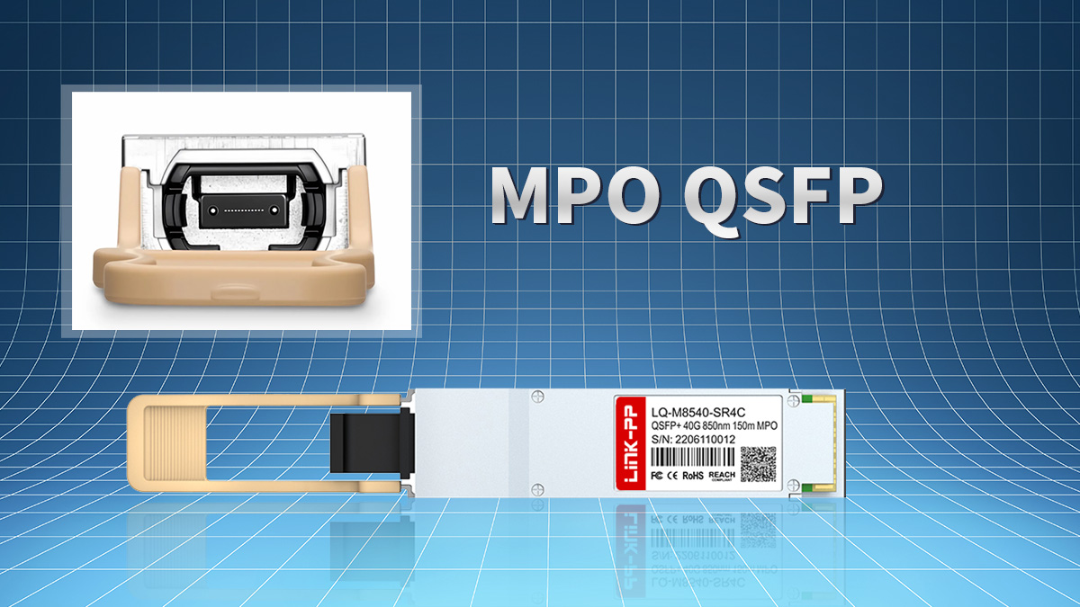
MPO QSFP Definition and Core Concept
An MPO QSFP module combines two key elements: the QSFP form factor and an MPO fiber interface. The QSFP form factor defines the electrical and mechanical interface used in network switches, while the MPO connector allows multiple optical lanes to be transmitted simultaneously through a single multi-fiber cable.
Unlike LC-based QSFP modules that transmit data over one fiber pair, MPO QSFP modules use parallel optics. Each lane carries part of the total bandwidth, and together they form the full link speed. For example, a 40Gbps MPO QSFP module typically transmits four 10Gbps lanes in parallel, while a 100Gbps version may use four 25Gbps lanes.
Why MPO Is Used in QSFP Transceivers
MPO connector is used in QSFP modules primarily to support high-density and high-bandwidth connections in data centers. Parallel transmission reduces the need for multiple duplex fiber runs and allows a single trunk cable to support multiple channels.
MPO QSFP is commonly chosen when networks require:
-
High port density on switches
-
Structured cabling with trunk and harness systems
-
Short-reach high-bandwidth links
-
Breakout from high-speed ports to multiple lower-speed links
This approach simplifies large-scale deployments, especially in spine-leaf architectures where many high-speed links must be connected within limited rack space.
Typical MPO Fiber Configurations
Most MPO QSFP modules use 8-fiber or 12-fiber configurations depending on the optical standard. The exact fiber usage depends on whether the module transmits in parallel or uses single-mode multiplexing.
MPO QSFP modules typically follow these configurations:
| QSFP Type | Typical Fibers Used | Transmission Mode | Common Connector |
|---|---|---|---|
| 40G SR4 | 8 fibers | Parallel MMF | MPO-12 |
| 100G SR4 | 8 fibers | Parallel MMF | MPO-12 |
| 100G PSM4 | 8 fibers | Parallel SMF | MPO-12 |
| 100G DR4 | 8 fibers | Parallel SMF | MPO-12 |
Although many MPO connectors physically contain 12 fibers, only 8 are often used for transmission in SR4 and PSM4 modules, with the remaining fibers reserved or unused. Understanding this structure is important when selecting trunk cables and ensuring correct polarity in MPO QSFP deployments.
✅ How MPO QSFP Connectivity Works
MPO QSFP connectivity works by transmitting multiple optical lanes in parallel through a single multi-fiber MPO connector, allowing high-speed links such as 40Gbps and 100Gbps to be carried over one physical interface. Instead of using one transmit and one receive fiber pair, MPO QSFP modules distribute the total bandwidth across several fibers that operate simultaneously.
This parallel approach is what enables higher port density and scalable cabling in modern data centers.
Parallel Optical Transmission Explained
MPO QSFP modules rely on parallel optics, where each optical lane carries a portion of the total data rate. These lanes operate independently but are synchronized to form a single high-speed link between devices.
In most MPO QSFP modules, the total bandwidth is divided across four transmit fibers and four receive fibers.
| Module Type | Lane Structure | Total Speed | Fiber Type |
|---|---|---|---|
| QSFP+ SR4 | 4×10Gbps | 40Gbps | MMF |
| QSFP28 SR4 | 4×25Gbps | 100Gbps | MMF |
| QSFP28 PSM4 | 4×25Gbps | 100Gbps | SMF |
| QSFP28 DR4 | 4×25Gbps | 100Gbps | SMF |
Each transmit lane sends data on a dedicated fiber, and each receive lane uses a separate fiber. This is why most MPO QSFP modules use 8 active fibers even when the connector supports 12.
Parallel transmission reduces signal complexity inside the module and allows high speeds without requiring complex wavelength multiplexing for short- and mid-reach links.
MPO Connector Structure and Fiber Layout
MPO connectors used with QSFP modules typically contain 12 or 24 fibers arranged in a single row. However, many QSFP parallel optics modules only use 8 of those fibers.
Most MPO QSFP SR4, PSM4, and DR4 modules use 4 transmit fibers and 4 receive fibers.
| MPO Type | Total Fibers | Active Fibers | Common Use |
|---|---|---|---|
| MPO-12 | 12 | 8 | 40G/100G SR4 |
| MPO-12 | 12 | 8 | 100G PSM4 |
| MPO-24 | 24 | 16 | High-density trunks |
The unused fibers in a 12-fiber MPO connector are typically positioned in the center. Proper alignment and polarity are required to ensure transmit fibers on one module connect to receive fibers on the other.
Because MPO uses multiple fibers, correct polarity management is critical for link operation.
Polarity and Alignment Considerations
MPO QSFP links require correct polarity so that transmit lanes on one device connect to receive lanes on the other. Unlike LC duplex links, where polarity is relatively simple, MPO systems must account for multi-fiber alignment across trunk cables and patch panels.
When designing MPO QSFP links, engineers must consider:
-
Type A, B, or C polarity methods
-
MPO trunk cable configuration
-
Key-up vs key-down alignment
-
Breakout cable mapping
Incorrect polarity can prevent links from coming up even if fiber and modules are functional. For this reason, MPO QSFP deployments typically follow standardized cabling systems with pre-terminated trunks and harness cables.
Understanding how parallel lanes, fiber layout, and polarity interact ensures that MPO QSFP links operate reliably and scale efficiently in high-density network environments.
✅ Common Types of MPO QSFP Transceivers
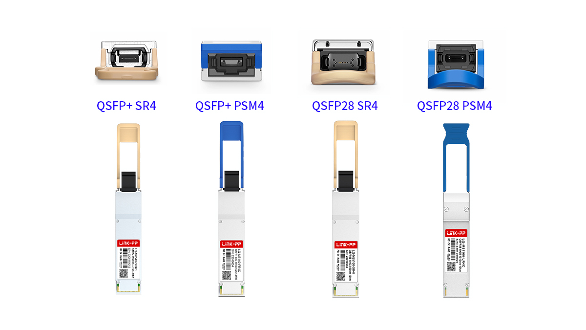
MPO QSFP transceivers are most commonly found in 40Gbps and 100Gbps parallel optical modules designed for high-density data center links. The exact type depends on transmission distance, fiber type, and whether the link uses multimode or single-mode cabling. In practice, most deployments center around SR4, PSM4, and DR4 variants.
These module types share the same QSFP form factor and MPO connector interface but differ in wavelength, fiber type, and supported reach.
QSFP+ 40G MPO Modules
40Gbps MPO QSFP modules are typically used for short-reach multimode connections inside data centers. The most widely deployed option is QSFP+ SR4, which uses parallel multimode fibers for high-density switch-to-switch links.
40G MPO QSFP modules are primarily designed for short-distance multimode transmission within a rack or between nearby racks.
| Module Type | Fiber Type | Typical Distance | Connector |
|---|---|---|---|
| QSFP+ SR4 | MMF (OM3) | 70m | MPO-12 |
| QSFP+ SR4 | MMF (OM4) | 100m | MPO-12 |
| QSFP+ PSM4 | SMF | 500m | MPO-12 |
QSFP+ SR4 is the dominant 40G MPO option for multimode structured cabling. QSFP+ PSM4, while less common today, is used when short-reach single-mode parallel transmission is required without wavelength multiplexing.
QSFP28 100G MPO Modules
For 100Gbps links, MPO-based QSFP28 modules are widely deployed across modern spine-leaf architectures. These modules use four parallel lanes at 25Gbps each to achieve 100Gbps total throughput.
Most 100G MPO QSFP modules use 8 active fibers and are designed for either multimode short reach or single-mode structured cabling.
| Module Type | Fiber Type | Typical Distance | Connector |
|---|---|---|---|
| QSFP28 SR4 | MMF (OM4) | 100m | MPO-12 |
| QSFP28 PSM4 | SMF | 500m | MPO-12 |
| QSFP28 DR4 | SMF | 500m | MPO-12 |
QSFP28 SR4 is commonly used for short-range multimode connections within a data hall. QSFP28 PSM4 and DR4 support single-mode fiber and are often chosen for structured cabling across larger data center spaces where multimode distance is insufficient.
Multimode vs Single-Mode MPO QSFP Selection
Choosing between multimode and single-mode MPO QSFP depends primarily on distance, infrastructure, and future scalability requirements.
Multimode MPO QSFP modules are typically used for short in-row links, while single-mode versions are used for longer structured cabling runs or when future upgrade flexibility is required.
| Fiber Category | Typical Modules | Distance Range | Deployment Scenario |
|---|---|---|---|
| Multimode MMF | SR4 | up to 100m | Rack-to-rack links |
| Single-mode SMF | PSM4 / DR4 | up to 500m | Spine-leaf links |
Multimode solutions generally offer lower transceiver cost but shorter reach. Single-mode MPO QSFP modules support longer distances and more flexible architectures, especially in large-scale data centers where cabling longevity is a priority.
✅ MPO QSFP Fiber Standards and Distance Capabilities
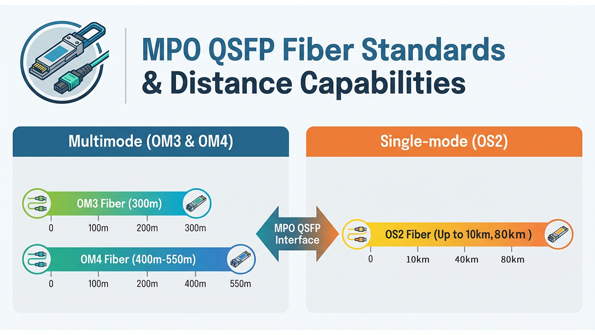
MPO QSFP transceivers support different fiber standards and transmission distances depending on whether they use multimode or single-mode optics. In most deployments, multimode MPO QSFP modules are used for short in-row links, while single-mode versions are selected for longer structured cabling across a data center.
Understanding fiber type, supported distance, and link budget limits is essential when designing reliable MPO QSFP connections.
Multimode MPO QSFP Distance Standards
Multimode MPO QSFP modules are typically based on SR4 optics and operate over OM3 or OM4 multimode fiber. These are optimized for short-reach, high-density links where cost and ease of installation are key priorities.
Multimode MPO QSFP modules are best suited for short-distance connections inside a data hall, typically within the same row or between nearby racks.
| Module Type | Fiber Standard | Typical Distance | Wavelength |
|---|---|---|---|
| 40GBASE-SR4 | OM3 MMF | 70m | 850nm |
| 40GBASE-SR4 | OM4 MMF | 100m | 850nm |
| 100GBASE-SR4 | OM3 MMF | 70m | 850nm |
| 100GBASE-SR4 | OM4 MMF | 100m | 850nm |
OM4 fiber provides improved bandwidth and allows slightly longer reach than OM3. For most modern data centers, OM4 is the preferred multimode standard when deploying new MPO trunk infrastructure.
Multimode MPO QSFP links are commonly used for:
-
Top-of-rack to aggregation switch links
-
Leaf-to-spine connections within a row
-
High-density patch panel environments
Because multimode distance is limited, it is generally not used for cross-hall or campus links.
Single-Mode MPO QSFP Distance Standards
Single-mode MPO QSFP modules support longer reach and are commonly used in structured cabling systems that must scale beyond short rack-to-rack distances. These modules use parallel transmission over single-mode fibers rather than wavelength multiplexing.
Single-mode MPO QSFP modules are typically used when link distances exceed multimode limits or when long-term scalability is required.
| Module Type | Fiber Type | Typical Distance | Use Case |
|---|---|---|---|
| QSFP28 PSM4 | SMF | 500m | Data hall links |
| QSFP28 DR4 | SMF | 500m | Spine-leaf links |
| QSFP28 FR4 | SMF | 2km | (non-MPO, LC) |
PSM4 and DR4 are both parallel single-mode MPO solutions using 8 active fibers. They are often chosen for spine-leaf architectures where distances exceed multimode limits but do not require long-reach LR optics.
Although FR4 supports longer distances, it uses LC connectors and wavelength multiplexing rather than MPO parallel transmission, so it falls outside typical MPO QSFP deployments.
Distance Planning and Link Budget Considerations
Actual MPO QSFP link distance depends not only on the module specification but also on total link loss across connectors, patch panels, and trunk cables. Parallel optics systems often include multiple connection points, which increases insertion loss compared with simple duplex LC links.
When planning MPO QSFP links, consider:
-
Total number of MPO connections in the channel
-
Fiber quality and cleanliness
-
Patch panel and cassette loss
-
Cable length and routing
-
Transceiver link budget
Exceeding the supported loss budget can prevent links from establishing even if the fiber distance is within specification. For this reason, structured MPO cabling systems are typically designed with defined loss limits and tested before deployment.
Careful selection of fiber standard and distance capability ensures that MPO QSFP links remain stable, scalable, and aligned with future bandwidth upgrades.
✅ MPO QSFP vs LC QSFP Transceivers
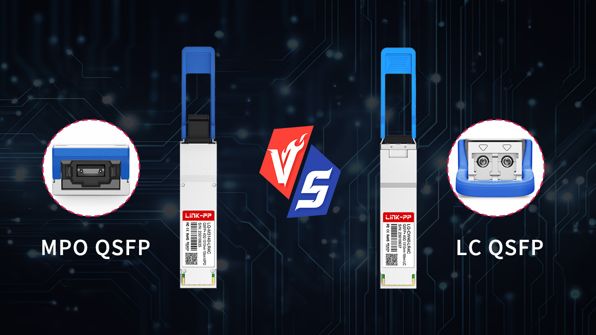
MPO QSFP and LC QSFP transceivers differ primarily in how they connect to fiber: MPO QSFP uses multi-fiber parallel transmission for high-density short-to-mid-reach links, while LC QSFP uses duplex fiber and is typically chosen for longer distances or simpler cabling. The choice between them depends on distance, cabling architecture, scalability needs, and port density requirements.
In modern data centers, both approaches are widely used but serve different roles in network design.
Connector and Transmission Differences
MPO QSFP modules transmit data across multiple fibers simultaneously using parallel optics, while LC QSFP modules use two fibers (one transmit, one receive) and often rely on wavelength multiplexing or serial transmission.
MPO QSFP is optimized for high-density parallel links, whereas LC QSFP is optimized for longer reach and simpler duplex connectivity.
| Feature | MPO QSFP | LC QSFP |
|---|---|---|
| Connector type | MPO multi-fiber | Duplex LC |
| Fiber count | 8–12 fibers | 2 fibers |
| Transmission mode | Parallel lanes | Duplex / WDM |
| Typical speeds | 40Gbps, 100Gbps | 10Gbps–100Gbps |
Because MPO QSFP uses multiple fibers, it can support breakout and high-density trunk cabling. LC QSFP, by contrast, is easier to deploy in environments with existing duplex fiber infrastructure.
Distance and Deployment Scenarios
Distance capability is one of the main deciding factors between MPO and LC QSFP modules. Parallel MPO optics are usually designed for short-to-medium reach, while LC-based modules support longer distances using wavelength multiplexing.
MPO QSFP is typically used for short structured cabling inside data centers, while LC QSFP is used for longer switch-to-switch or building-to-building links.
| Deployment Scenario | Preferred Option | Reason |
|---|---|---|
| Rack-to-rack (short reach) | MPO QSFP | High density, parallel MMF |
| Spine–leaf within data hall | MPO QSFP | Structured trunk cabling |
| Cross-hall links | LC QSFP | Longer reach |
| Campus or metro links | LC QSFP | Single-mode distance |
In many networks, MPO QSFP is used for high-density internal links, while LC QSFP modules handle longer interconnects between rows or buildings.
Cabling Complexity and Scalability
MPO QSFP systems require structured cabling with trunk cables, cassettes, and polarity management. While this introduces design complexity, it also allows for scalable, high-density deployments where many high-speed ports must be connected.
LC QSFP deployments are simpler because they use standard duplex fiber. However, scaling to very high port densities can require more individual cables and patching.
When evaluating cabling architecture, consider:
-
Whether a structured MPO trunk system already exists
-
Required port density on switches
-
Future bandwidth upgrade plans
-
Need for breakout to lower speeds
-
Available fiber infrastructure
MPO QSFP is often preferred in newly built data centers designed for high-density parallel optics. LC QSFP remains common in environments prioritizing reach, compatibility, and simpler cabling management.
Understanding how MPO and LC QSFP differ helps ensure that optical modules, fiber infrastructure, and network architecture are aligned with both current performance requirements and future scalability plans.
✅ Typical Applications of MPO QSFP
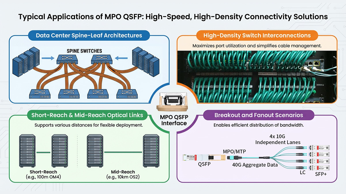
MPO QSFP transceivers are primarily used in high-density data center environments where multiple high-speed links must be deployed efficiently over structured cabling systems. They are especially common in 40Gbps and 100Gbps spine–leaf architecture, short-reach switch interconnections, and breakout scenarios that require parallel optical transmission.
Because MPO QSFP modules use multi-fiber connectors and parallel lanes, they are best suited for environments that prioritize scalability, port density, and structured fiber management rather than long-distance transmission.
Spine–Leaf Data Center Architectures
MPO QSFP modules are widely deployed in spine–leaf networks where a large number of high-speed connections must be established between switches. Parallel optics allow multiple lanes to run through a single MPO trunk cable, reducing cabling congestion and improving airflow within racks.
MPO QSFP is commonly used for high-speed leaf-to-spine links where many parallel connections must be deployed over short to medium distances.
| Network Layer | Typical Module | Fiber Type | Distance |
|---|---|---|---|
| Leaf to spine | QSFP28 SR4 | MMF | up to 100m |
| Leaf to spine | QSFP28 DR4 | SMF | up to 500m |
| Spine to spine | QSFP28 PSM4 | SMF | up to 500m |
In large-scale deployments, MPO trunk cables run between rows or patch panels, while MPO QSFP modules connect directly into switches. This structured approach simplifies installation and supports future upgrades to higher speeds.
High-Density Switch Interconnections
When multiple high-speed ports must be connected within limited rack space, MPO QSFP modules help reduce cable count and improve cable organization. A single MPO trunk can replace multiple duplex fiber runs, which is especially valuable in high-density switch environments.
Typical use cases include:
-
Top-of-rack to end-of-row switching
-
Aggregation switch interconnections
-
Data hall cross-connect areas
-
High-port-count switch deployments
Parallel MPO links help maintain manageable cable routing even as port counts increase.
Breakout and Fanout Scenarios
One of the most common applications of MPO QSFP modules is breakout connectivity, where a single high-speed port is split into multiple lower-speed links. This allows network designers to maximize port utilization and maintain flexibility during network upgrades.
MPO QSFP modules support breakout to multiple lower-speed connections using MPO–LC harness cables.
| High-Speed Port | Breakout Type | Resulting Links | Connector |
|---|---|---|---|
| 40G SR4 | 4×10G | Four 10G links | LC duplex |
| 100G SR4 | 4×25G | Four 25G links | LC duplex |
| 100G DR4 | 4×25G | Four 25G SMF links | LC duplex |
Breakout capability is particularly useful during migration phases, such as upgrading from 10Gbps to 40Gbps or from 25Gbps to 100Gbps networks. It allows existing infrastructure to be reused while gradually transitioning to higher speeds.
Structured Cabling with MPO Trunk Systems
MPO QSFP modules are often deployed within structured cabling systems that use MPO trunk cables, patch panels, and cassettes. This approach centralizes fiber management and enables easier scaling as bandwidth demands grow.
Common structured cabling scenarios include:
-
Pre-terminated MPO trunk installations
-
Data center patch panel cross-connects
-
Modular fiber distribution systems
-
High-density fiber pathways
In these environments, MPO QSFP modules connect directly to MPO trunks or through patch panels, enabling flexible and scalable optical connectivity across the data center.
By aligning MPO QSFP deployments with structured cabling and high-density switching needs, network designers can build scalable infrastructures that support current bandwidth requirements while preparing for future upgrades.
✅ MPO QSFP Breakout and Fanout Scenarios
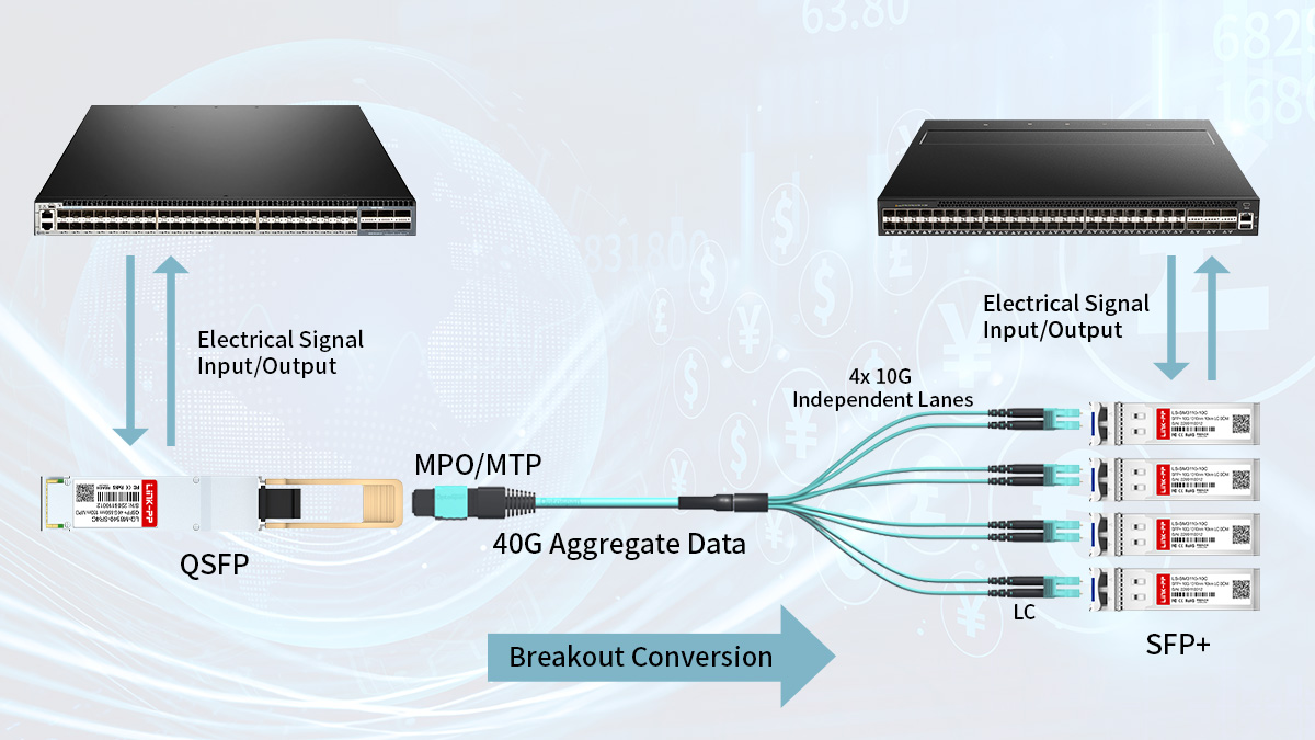
MPO QSFP breakout and fanout allow a single high-speed QSFP port to be split into multiple lower-speed links using MPO harness cables or breakout modules. This is commonly used to convert 40Gbps or 100Gbps parallel optics into multiple 10Gbps or 25Gbps connections, improving port utilization and enabling gradual network upgrades.
Breakout is one of the main reasons MPO QSFP modules are widely deployed in data centers, as it provides flexibility when connecting different generations of network equipment.
Breakout from 40G and 100G MPO QSFP Ports
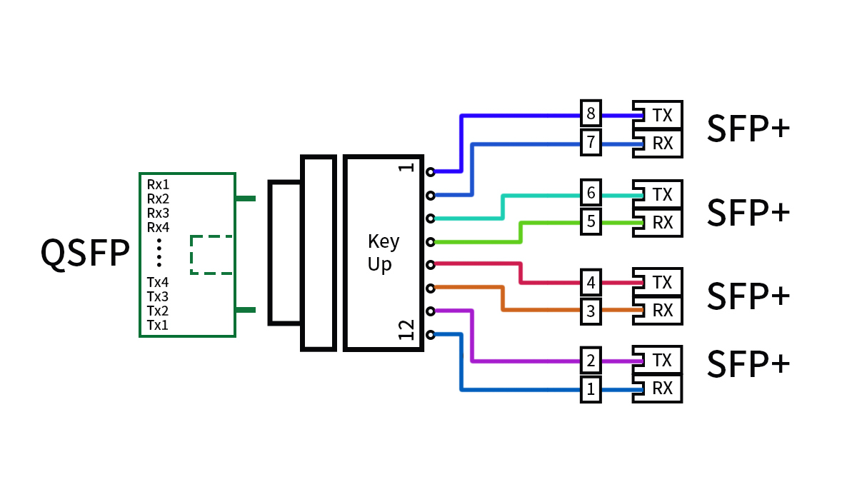
Most MPO QSFP modules support lane-level breakout because their bandwidth is transmitted over multiple parallel fibers. Each optical lane can operate as an independent lower-speed link when connected through an MPO-to-LC harness cable and supported by the switch configuration.
MPO QSFP breakout typically divides one high-speed port into four lower-speed duplex links.
| High-Speed Module | Lane Structure | Breakout Result | Cable Type |
|---|---|---|---|
| QSFP+ SR4 | 4×10Gbps | 4×10G SFP+ | MPO–LC harness |
| QSFP28 SR4 | 4×25Gbps | 4×25G SFP28 | MPO–LC harness |
| QSFP28 DR4 | 4×25Gbps | 4×25G SMF links | MPO–LC harness |
For breakout to work, both the transceiver and the switch port must support breakout mode. Many modern data center switches allow QSFP ports to be configured as four independent lanes through software settings.
Breakout is often used when migrating from lower-speed to higher-speed infrastructure, allowing existing equipment to remain in service during transition phases.
MPO Harness Cables and Fanout Mapping
Breakout connections are achieved using MPO-to-LC harness cables that map individual fibers in the MPO connector to separate duplex LC connectors. Proper mapping ensures that transmit lanes align with receive lanes on the connected devices.
Correct fiber mapping and polarity are essential for successful MPO QSFP breakout.
| Harness Type | MPO End | LC Ends | Typical Use |
|---|---|---|---|
| 8-fiber MPO harness | MPO-12 | 4×LC duplex | 40G/100G breakout |
| Single-mode harness | MPO-12 | 4×LC duplex | 100G DR4 breakout |
| Multimode harness | MPO-12 | 4×LC duplex | 40G/100G SR4 breakout |
These harness cables are usually polarity-managed and pre-terminated to ensure proper alignment. Using incorrect polarity or mapping can prevent links from establishing even when all components are functional.
When to Use Breakout vs Direct MPO Links
Not all deployments require breakout. In some cases, a direct MPO-to-MPO connection between two QSFP modules is preferred, particularly when connecting switches operating at the same speed.
Breakout is typically used when:
-
Connecting a high-speed QSFP port to multiple lower-speed ports
-
Migrating from 10Gbps or 25Gbps to 40Gbps or 100Gbps
-
Maximizing switch port utilization
-
Supporting mixed-speed environments
Direct MPO links are typically used when:
-
Both ends operate at the same speed
-
Structured MPO trunk cabling is already in place
-
High-density switch-to-switch links are required
Choosing between breakout and direct MPO connectivity depends on network architecture, equipment capabilities, and future upgrade plans. When designed correctly, MPO QSFP breakout provides a flexible way to scale bandwidth while maintaining compatibility with existing infrastructure.
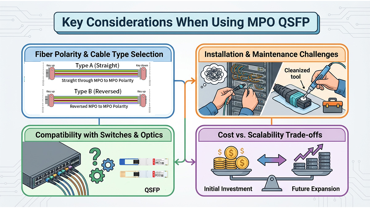
✅ Key Considerations When Using MPO QSFP
MPO QSFP modules offer high-density and scalable connectivity, but successful deployment depends on proper planning around fiber type, polarity, compatibility, and link design. Because MPO systems involve multiple fibers and structured cabling, they require more upfront design consideration than simple duplex LC links.
Before deploying MPO QSFP modules, network designers should evaluate distance requirements, cabling infrastructure, breakout needs, and long-term scalability.
Fiber Type and Distance Planning
Selecting the correct fiber type is one of the most important decisions when deploying MPO QSFP. Multimode and single-mode MPO modules support different distance ranges and are typically used in different parts of a data center.
Multimode MPO QSFP is generally used for short in-row links, while single-mode MPO QSFP is used for longer structured cabling across a data hall.
| Fiber Type | Common Modules | Typical Distance | Deployment Scenario |
|---|---|---|---|
| Multimode MMF | SR4 | up to 100m | Rack-to-rack |
| Single-mode SMF | PSM4, DR4 | up to 500m | Spine–leaf |
| Duplex SMF (LC) | LR4/FR4 | 2km+ | Long links |
Choosing the wrong fiber type can limit future upgrades or require costly recabling. Many newer data centers adopt single-mode MPO infrastructure to maintain flexibility as speeds increase.
Polarity and Cabling Architecture
MPO QSFP deployments rely on correct fiber polarity to ensure transmit fibers connect to receive fibers. Unlike LC duplex links, MPO links involve multiple fibers and often pass through trunk cables and patch panels.
Incorrect polarity is one of the most common causes of MPO QSFP link failures.
When planning cabling, consider:
-
Polarity method (Type A, B, or C)
-
MPO trunk cable configuration
-
Patch panel and cassette layout
-
Key orientation (key-up/key-down)
-
Harness cable mapping
Using pre-terminated structured cabling systems can help maintain consistent polarity and reduce installation errors.
Breakout Compatibility and Switch Support
Not all QSFP ports support breakout, and not all MPO QSFP modules are intended for breakout use. Switch configuration and transceiver type must align with the intended deployment.
Breakout requires both hardware support in the switch and correct transceiver lane configuration.
| Scenario | Requirement | Notes |
|---|---|---|
| 40G to 4×10G | QSFP+ SR4 + breakout support | Common in legacy upgrades |
| 100G to 4×25G | QSFP28 SR4/DR4 + switch config | Widely supported |
| Direct 100G link | Matching QSFP modules | No breakout needed |
Before deployment, verify:
-
Switch port breakout capability
-
Firmware support
-
Correct harness cable type
-
Lane mapping compatibility
Ignoring breakout compatibility can lead to non-functional links even when hardware appears correct.
Link Budget and Connection Loss
MPO QSFP links often include multiple connection points such as trunks, patch panels, and cassettes. Each connection introduces insertion loss, which affects overall link performance.
Total channel loss must remain within the transceiver link budget for the connection to operate reliably.
Key factors affecting link performance:
-
Number of MPO connections
-
Connector cleanliness
-
Cable quality
-
Patch panel loss
-
Total fiber length
Testing and cleaning MPO connectors before installation is critical, as contamination can significantly increase insertion loss.
Future Scalability and Upgrade Paths
MPO QSFP infrastructure is often deployed with future bandwidth upgrades in mind. Choosing the right cabling and module type can simplify migration from 40Gbps to 100Gbps or beyond.
When planning for scalability, consider:
-
Whether current cabling supports higher speeds
-
Potential migration to 200G or 400G
-
Reuse of MPO trunk cables
-
Compatibility with future transceivers
-
Data center expansion plans
A well-designed MPO QSFP cabling system can support multiple upgrade cycles without requiring major infrastructure changes.
Careful planning across fiber type, polarity, breakout support, and link budget ensures that MPO QSFP deployments remain stable, scalable, and aligned with long-term network requirements.
✅ FAQs About MPO QSFP Transceiver
Q1: What is an MPO QSFP transceiver?
An MPO QSFP is a QSFP optical module that uses an MPO multi-fiber connector to transmit multiple lanes in parallel, typically for 40Gbps or 100Gbps data center links.
Q2: How many fibers does MPO QSFP use?
Most MPO QSFP modules use 8 active fibers (4 transmit + 4 receive) within a 12-fiber MPO connector.
Q3: Does MPO QSFP support breakout?
Yes. Many 40G and 100G MPO QSFP modules can break out into four lower-speed links (4×10G or 4×25G) if the switch port supports breakout mode.
Q4: Is MPO QSFP used for long-distance links?
No. MPO QSFP is mainly used for short to mid-range data center links. Longer distances typically use LC-based QSFP modules.
Q5: Can MPO QSFP be used with existing duplex fiber?
Only through breakout cables. MPO QSFP cannot connect directly to a single duplex LC link without splitting into multiple lanes.
Q6: When is MPO QSFP preferred over LC QSFP?
MPO QSFP is preferred in high-density data center cabling where many high-speed links must be deployed efficiently over structured fiber trunks.
✅ Conclusion
MPO QSFP transceivers enable high-density, parallel optical connectivity for modern data center networks, particularly in 40Gbps and 100Gbps spine–leaf architectures. By using MPO multi-fiber connectors, they support scalable cabling, efficient breakout, and simplified high-port-count deployments compared with traditional duplex fiber solutions. Understanding module types, fiber standards, distance limits, and breakout design ensures that MPO QSFP links are deployed correctly and aligned with long-term infrastructure planning.
For network engineers and integrators designing high-speed optical links, choosing reliable and fully compatible MPO QSFP modules is essential to maintaining stable performance and scalable growth. If you are evaluating MPO QSFP options for your deployment, you can explore tested compatibility solutions and detailed specifications through the LINK-PP Official Store, where a full range of MPO-based QSFP transceivers and cabling options are available for different network scenarios.







