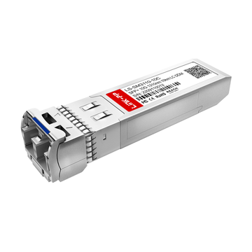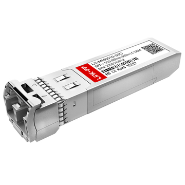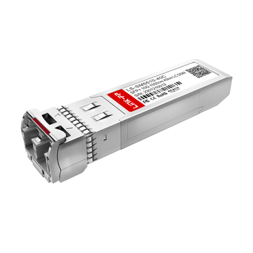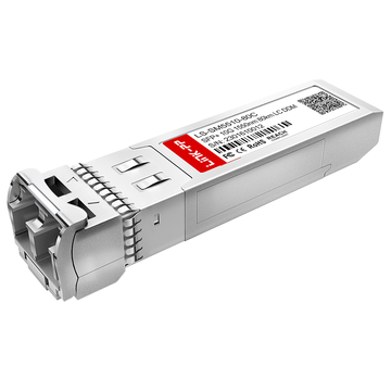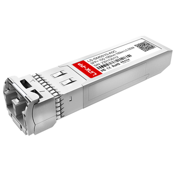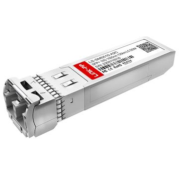
Das rasante Wachstum von 10GbE-Netzwerken in Unternehmens- und Rechenzentrumsumgebungen hat optische Transceiver zu einem zentralen Baustein moderner Infrastrukturen gemacht. SFP+-Kurzstreckenmodule spielen dabei eine entscheidende Rolle für die Ermöglichung von Hochgeschwindigkeits- und latenzarmen Verbindungen über Multimode-Fasern. Mit der Weiterentwicklung von Switching-Plattformen wird ein präzises Verständnis der Spezifikationen optischer Module unerlässlich, um eine vorhersehbare Netzwerkleistung zu gewährleisten.
Der Juniper EX-SFP-10GE-SR Transceiver ist für 10GBASE-SR-Anwendungen konzipiert und arbeitet mit 850 nm über Multimode-Fasern, um Hochgeschwindigkeitsverbindungen über kurze Distanzen zu ermöglichen. Sein Datenblatt definiert neben dem optischen Übertragungsverhalten auch elektrische, mechanische und Konformitätsgrenzen, die die Leistung des Moduls im realen Einsatz bestimmen. Für Ingenieure und Netzwerkdesigner bilden diese Parameter die Grundlage für eine präzise Verbindungsplanung und Systemvalidierung.
Dieser Artikel bietet eine strukturierte Aufschlüsselung des Datenblatts des Juniper EX-SFP-10GE-SR, um dessen technische Spezifikationen und Leistungsmerkmale zu verdeutlichen. Er konzentriert sich auf die wichtigsten technischen Aspekte, die den Betrieb in Umgebungen der EX-Serie bestimmen, darunter:
- Optisches Übertragungs- und Leistungsbudgetverhalten
- Anforderungen an elektrische Schnittstellen und Hochgeschwindigkeitssignale
- Timing-, Jitter- und Signalintegritätsbeschränkungen
- Mechanische Konstruktion, thermische Grenzwerte und Konformitätsnormen
Diese Aspekte definieren gemeinsam, wie sich das Modul als komplettes optisches Subsystem innerhalb von Hochgeschwindigkeits-Ethernet-Netzwerken verhält und bilden die Grundlage für zuverlässige Design- und Einsatzentscheidungen.
🏮 Was ist der Juniper EX-SFP-10GE-SR Transceiver?
Der Juniper EX-SFP-10GE-SR Transceiver ist ein optisches 10-Gbit/s-Kurzstreckenmodul für die 10GBASE-SR-Ethernet-Übertragung über Multimode-Faser. Er bietet eine standardisierte SFP+-Schnittstelle für schnelle optische Verbindungen zwischen Switches der Juniper EX-Serie und kompatiblen Netzwerkgeräten. Die Spezifikationen im Datenblatt basieren auf strengen optischen, elektrischen und mechanischen Parametern, die eine zuverlässige Leistung in Umgebungen mit hoher Switching-Dichte gewährleisten.
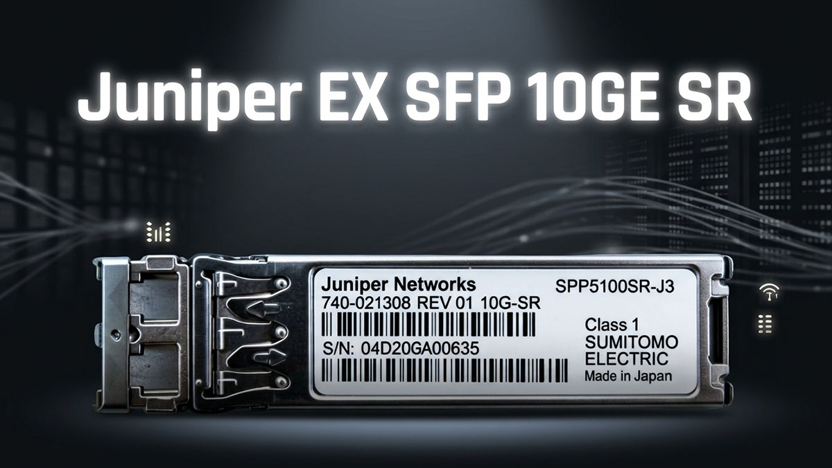
Übersicht über das optische 10GBASE-SR SFP+ Modul
Der Juniper EX-SFP-10GE-SR ist ein IEEE 802.3ae-konformer optischer Kurzstrecken-Transceiver, der speziell für die Multimode-Glasfaserübertragung mit einer 850-nm-VCSEL-Laserquelle optimiert ist. Er unterstützt eine feste Datenrate von 10.3125 Gbit/s, die der Standard-Signalrate für 10GbE-Ethernet entspricht.
Dieses Modul wird in Datenblättern typischerweise anhand seiner physikalischen und optischen Eigenschaften und nicht anhand von Anwendungsszenarien definiert. Zu den wichtigsten definierenden Merkmalen gehören:
- Optischer Sender auf 850-nm-VCSEL-Basis
- Multimode-Faserbetrieb (OM3/OM4 unterstützt)
- LC-Duplex-optische Schnittstelle
- SFP+ Hot-Plug-fähiger mechanischer Formfaktor
Diese Parameter bestimmen gemeinsam, wie sich das Modul als Gerät der physikalischen Schicht innerhalb der Ethernet-Infrastruktur verhält und gewährleisten so die Kompatibilität mit standardisierten 10GBASE-SR-Verbindungen anstelle von anwendungsspezifischen Konfigurationen.
Position im optischen Portfolio der Juniper EX-Serie
Innerhalb der Juniper EX-Serie ist das EX-SFP-10GE-SR-Modul als Uplink-Transceiver mit kurzer Reichweite für die Vernetzung innerhalb von Gebäuden oder Rechenzentren konzipiert. Es ist Teil des optischen SFP+-Ökosystems und unterstützt die modulare Porterweiterung von EX-Switches.
Seine Rolle im Portfolio wird eher durch die Einschränkungen auf Datenblattebene als durch die Absicht des Netzwerkdesigns definiert:
- Konzipiert für SFP+ 10GbE Uplink-Ports in Switches der EX-Serie
- Unterstützt standardisierte optische Kurzstreckenverbindungen innerhalb von Switch-Architekturen
- Funktioniert als optische Schnittstelle mit festen Spezifikationen ohne abstimmbares Wellenlängenverhalten
Technisch gesehen dient es als deterministische optische PHY-Komponente, was bedeutet, dass seine Leistung vollständig durch definierte optische Leistungsbereiche, Empfängerempfindlichkeitsgrenzen und elektrische Schnittstellenspezifikationen bestimmt wird, die im Datenblatt dokumentiert sind.
Kerndatenblatt: Definition und Funktionsumfang
Aus Sicht des Datenblatts wird das Juniper EX-SFP-10GE-SR nicht durch sein Anwendungsszenario, sondern durch seine technischen Anforderungen in verschiedenen Bereichen definiert. Diese Anforderungen legen die Grenzen fest, innerhalb derer das Modul betrieben werden muss, um Konformität und Signalintegrität zu gewährleisten.
Der Funktionsumfang umfasst typischerweise:
- Optische Parameter: Sendeleistung, Empfangsempfindlichkeit, Extinktionsverhältnis und Wellenlängenstabilität
- Elektrische Parameter: Versorgungsspannungsbereich, Stromaufnahme und Eigenschaften der seriellen Hochgeschwindigkeitsschnittstelle
- Mechanische Parameter: Abmessungen des SFP+-Formfaktors, Steckertyp und Einstecktoleranzen
- Umgebungsparameter: Betriebstemperaturbereich und Wärmeableitungsgrenzen
- Konformitätsparameter: IEEE 802.3ae, SFP+ MSA und Lasersicherheitsstandards
Zusammen definieren diese Spezifikationen das Modul als vollständig charakterisierten Transceiver der physikalischen Schicht. In der Praxis dient das Datenblatt als maßgebliche Referenz, um festzustellen, ob der Juniper EX-SFP-10GE-SR die Signalintegrität aufrechterhalten, die Linkbudget-Anforderungen erfüllen und innerhalb der definierten Systembeschränkungen zuverlässig arbeiten kann.
🏮 Mechanische Spezifikationen und Formfaktor-Spezifikationen
Die mechanischen Spezifikationen und die Bauform des Juniper EX-SFP-10GE-SR definieren die physikalischen Anforderungen, die einen korrekten Sitz, zuverlässigen Betrieb und eine stabile optische Ausrichtung des Moduls in SFP+-Ports gewährleisten. Diese Datenblattparameter sind unerlässlich für die Interoperabilität zwischen Switches der Juniper EX-Serie und anderen kompatiblen SFP+-Hostsystemen.

Physikalische Abmessungen und Portdichtebeschränkungen von SFP+
Der Juniper EX-SFP-10GE-SR entspricht dem standardisierten SFP+-Gehäuse, das für kompakte Netzwerkumgebungen mit hoher Packungsdichte entwickelt wurde. Dank dieser standardisierten Bauform können mehrere Transceiver eng beieinander in einem einzigen Switch-Gehäuse installiert werden, ohne die Signalintegrität oder die Wärmeableitung zu beeinträchtigen.
Zu den wichtigsten mechanischen Eigenschaften gehören:
- Standardabmessungen für SFP+-Module gemäß MSA-Spezifikation
- Kompakte Bauform, optimiert für hohe Portdichte bei Switches der EX-Serie
- Feste mechanische Toleranzen gewährleisten den korrekten Sitz in Käfigbaugruppen
- Strukturelle Auslegung, die wiederholte Einschubzyklen ohne Verformung ermöglicht
Diese physikalischen Beschränkungen beeinflussen direkt, wie viele optische Module pro Switch eingesetzt werden können, wodurch die mechanische Konstruktion zu einem Schlüsselfaktor bei der Planung von Netzwerkarchitekturen mit hoher Dichte wird.
Einsteckkraft und Hot-Plug-Zuverlässigkeit
Die Einsteckkraft und die Hot-Plug-Fähigkeit bestimmen das Verhalten des Moduls beim Ein- und Ausbau im laufenden Betrieb. Das Juniper EX-SFP-10GE-SR ist für den Hot-Swap-Betrieb ausgelegt und ermöglicht so Wartungsarbeiten oder Upgrades ohne Systemausfall.
Wichtige Aspekte, die auf Datenblattebene zu berücksichtigen sind, umfassen:
- Kontrollierte Einsetz- und Entnahmekraft zur Vermeidung von mechanischem Verschleiß
- Bügelverschlussmechanismus für sicheres Verriegeln und einfaches Entfernen
- Hot-Plug-Funktion ohne Beeinträchtigung benachbarter Ports oder des Systembetriebs
- Mechanische Haltbarkeit über mehrere Einsetz-/Entfernungszyklen hinweg
Diese Konstruktion gewährleistet, dass das Modul sowohl physikalische Stabilität als auch operative Flexibilität in kontinuierlich laufenden Netzwerkumgebungen beibehält.
LC-Duplex-Optische Schnittstellengeometrie
Die Geometrie der optischen Schnittstelle definiert die präzise Ausrichtung der LC-Duplex-Steckverbinder mit den internen optischen Komponenten des Transceivers. Diese Ausrichtung ist entscheidend, da selbst mikroskopische Abweichungen zu Einfügungsdämpfung oder Signalverschlechterung führen können.
Zu den wichtigsten strukturellen Merkmalen gehören:
- LC-Duplex-Steckverbinderstandard für 10GBASE-SR-Multimode-Glasfaserverbindungen
- Hochpräzise Ferrule-Ausrichtung für optimale Kern-zu-Kern-Kopplung
- Enge mechanische Toleranzen zur Minimierung von Einfügungsdämpfung und Rückflussdämpfung
- Empfindlichkeit gegenüber Verunreinigungen, daher sind saubere optische Schnittstellenoberflächen erforderlich.
Um die Bedeutung der Präzision von Steckverbindern zu verdeutlichen, lässt sich der Zusammenhang zwischen Ausrichtungsqualität und optischer Leistung wie folgt zusammenfassen:
| Mechanischer Faktor | Auswirkungen auf das optische Signal | Systemebeneneffekt |
|---|---|---|
| Ausrichtungsgenauigkeit der Ferrule | Regelt die Kernkopplungseffizienz | Beeinflusst den Einfügungsverlust |
| Qualität der Steckverbinder-Endfläche | Reduziert Reflexion und Streuung | Verbessert die Signalintegrität |
| Paarungswiederholbarkeit | Gewährleistet eine stabile Langzeitverbindung | Gewährleistet eine gleichbleibende Verbindungsleistung |
Diese mechanischen Eigenschaften gewährleisten, dass der Juniper EX-SFP-10GE-SR während seiner gesamten Betriebslebensdauer eine stabile optische Kopplungsleistung beibehält, selbst unter wiederholten Wartungszyklen und bei Einsatzbedingungen mit hoher Dichte.
🏮 Parameter für die Prüfung der elektrischen und optischen Konformität
Die Prüfparameter für die elektrische und optische Konformität des Juniper EX-SFP-10GE-SR definieren die Verifizierungsmethoden, mit denen bestätigt wird, dass das Modul die Anforderungen von IEEE 802.3ae 10GBASE-SR und die SFP+ MSA-Spezifikationen erfüllt. Diese im Datenblatt beschriebenen Testbedingungen gewährleisten, dass sowohl die elektrische Signalgebung als auch die optische Übertragung vor dem Einsatz in Produktionsnetzwerken innerhalb strenger Leistungsgrenzen liegen.

Konfiguration des Konformitätstests für 10GBASE-SR
Der Prüfaufbau für die Konformitätsprüfung definiert die standardisierte Laborumgebung zur Validierung der Transceiver-Leistung unter kontrollierten Bedingungen. Für den Juniper EX-SFP-10GE-SR simulieren diese Testkonfigurationen reale Betriebsbedingungen und isolieren gleichzeitig spezifische Leistungskennzahlen.
Zu den wichtigsten Merkmalen des Testaufbaus gehören:
- Standardisiertes Referenzhostsystem zur Validierung der elektrischen SFP+-Schnittstelle
- Optische Testgeräte, kalibriert für 850-nm-Multimode-Fasermessungen
- Gesteuerte Dämpfungselemente zur Simulation von Kanalverlustbedingungen
- Referenzsender und -empfänger gemäß IEEE 802.3ae-Spezifikationen
Diese kontrollierten Bedingungen gewährleisten, dass die Messergebnisse die intrinsische Leistung des Moduls und nicht die Variabilität des externen Systems widerspiegeln. Das Datenblatt definiert diese Testumgebungen, um reproduzierbare und vergleichbare Ergebnisse in verschiedenen Validierungslaboren zu garantieren.
Leistungsanforderungen an die Bitfehlerrate (BER).
Die Bitfehlerrate (BER) ist ein entscheidender Parameter zur Bewertung der Zuverlässigkeit optischer Hochgeschwindigkeits-Kommunikationssysteme. Der Juniper EX-SFP-10GE-SR muss unter definierten Belastungsbedingungen eine ausreichend niedrige BER aufweisen, um einen stabilen 10GbE-Betrieb zu gewährleisten.
Zu den wichtigsten BER-bezogenen Merkmalen gehören:
- Der angestrebte BER-Schwellenwert liegt typischerweise bei oder unter 10⁻¹² für 10GBASE-SR-Verbindungen.
- Messung unter ungünstigsten optischen Leistungs- und Temperaturbedingungen
- Empfindlichkeit gegenüber Signalverschlechterungen durch Jitter, Dämpfung und Rauschen
- Korrelation zwischen optischer Leistungsreserve und Stabilität der Fehlerleistung
Um die BER-Beschränkungen besser zu verstehen, lässt sich der Zusammenhang zwischen optischer Marge und Fehlerleistung wie folgt zusammenfassen:
| Optischer Zustand | BER-Verhalten | Systeminterpretation |
|---|---|---|
| Hohe optische Marge | Sehr niedriger BER | Stabile und zuverlässige Verbindung |
| Nahe der Schwellengrenze | Erhöhung der BER | Verminderte Signalrobustheit |
| Unterhalb der Empfindlichkeitsschwelle | Hohe Bitfehlerrate / Verbindungsabbruch | Wiederherstellung ungültiger Signale |
Diese Beziehungen definieren die minimalen Leistungsgrenzen, die für eine fehlerfreie Kommunikation in kompatiblen 10GbE-Systemen erforderlich sind.
Bedingungen für die Validierung der Interoperabilität
Interoperabilitätstests gewährleisten den korrekten Betrieb des Juniper EX-SFP-10GE-SR auf verschiedenen kompatiblen Netzwerkplattformen bei gleichbleibenden Leistungseigenschaften. Diese Tests validieren sowohl die elektrische Kompatibilität als auch die optische Signalintegrität unter Bedingungen mit Geräten verschiedener Hersteller.
Zu den wichtigsten Faktoren für die Validierung der Interoperabilität gehören:
- Plattformübergreifende Kompatibilität mit IEEE 802.3ae-konformen Geräten
- Überprüfung der Konsistenz der elektrischen SFP+-Signalisierung (SFI/XFI-Schnittstellen)
- Optische Wellenlängenausrichtung bei 850 nm für den Betrieb von Multimode-Fasern
- Überprüfung der Konsistenz der DOM-Telemetrie über verschiedene Hostsysteme hinweg
Diese Bedingungen gewährleisten den zuverlässigen Betrieb des Moduls in standardisierten Ethernet-Umgebungen ohne proprietäre Anpassungen. Konkret bestätigt die Interoperabilitätsvalidierung im Datenblatt, dass das Modul die universellen Anforderungen der physikalischen Schicht für optische 10GbE-Kurzstreckenübertragung erfüllt und somit ein vorhersehbares Verhalten in kompatiblen Netzwerkinfrastrukturen sicherstellt.
🏮 Optische Leistungsbudget- und Empfindlichkeitsspezifikationen
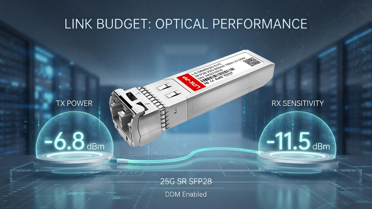
Die Spezifikationen für optisches Leistungsbudget und Empfindlichkeit des Juniper EX-SFP-10GE-SR definieren die grundlegenden Grenzen der Signalübertragung und des Signalempfangs über Multimode-Fasern. Diese Parameter bestimmen, ob eine 10-GbE-Verbindung ausreichend optische Reserve aufweist, um zuverlässig innerhalb der IEEE-10GBASE-SR-Anforderungen zu arbeiten. Im Datenblatt ausgedrückt: Dieser Abschnitt legt die Kerngrenze für die Realisierbarkeit optischer Verbindungen fest.
Optischer Sendeleistungsbereich (Sendeleistung)
Der optische Sendeleistungsbereich definiert, wie viel optische Energie das Modul bei 850 nm in die Faser einkoppelt. Dies ist ein kritischer Parameter, da er die Reichweite der Verbindung, die Signalstärke und die Kompatibilität mit Multimode-Faserkanälen direkt beeinflusst.
Typische, im Datenblatt angegebene Merkmale sind:
- Minimale Sendeleistung: Untergrenze, die unter ungünstigsten Bedingungen eine ausreichende Signalausgabe gewährleistet
- Maximale Sendeleistung: Obergrenze zur Vermeidung von Empfängerüberlastung oder nichtlinearen Verzerrungen
- Stabilitätsverhalten unter verschiedenen Temperaturschwankungen und Alterungsbedingungen
- Emissionskonsistenz auf VCSEL-Basis bei einer Modulationsrate von 10.3125 Gbit/s
Diese Werte werden streng kontrolliert, da übermäßige Abweichungen entweder zu einer unzureichenden Verbindungsreichweite oder zu einer Sättigung des Empfängers führen können, was beides die Signalintegrität in Hochgeschwindigkeits-Ethernet-Umgebungen beeinträchtigt.
Empfängerempfindlichkeit (Rx-Empfindlichkeit)
Die Empfängerempfindlichkeit definiert die minimale optische Leistung, die am Empfänger erforderlich ist, um eingehende Daten mit einer akzeptablen Bitfehlerrate (BER) korrekt zu interpretieren. Sie ist einer der wichtigsten Parameter für die Bestimmung der Verbindungszuverlässigkeit.
Zu den wichtigsten Merkmalen im Datenblatt gehören:
- Minimale detektierbare optische Leistungsschwelle unter Standardbedingungen
- BER-Konformitätsziel (typischerweise 10⁻¹² oder besser in 10GBASE-SR-Systemen)
- Rauschpegelbegrenzungen des Fotodetektors und des Empfängerverstärkers
- Degradationsverhalten unter Temperatur- und Alterungsbelastung
In der Praxis bedeuten niedrigere (negativere) Empfindlichkeitswerte eine bessere Empfängerleistung, wodurch das System höhere Kanalverluste tolerieren und gleichzeitig eine stabile Signalwiederherstellung gewährleisten kann.
Berechnungsmodell für die optische Linkbudgetierung
Die optische Link-Budgetierung definiert den maximal zulässigen Verlust zwischen Sender und Empfänger bei gleichzeitiger Aufrechterhaltung einer zuverlässigen Kommunikation. Sie wird direkt aus den im Datenblatt angegebenen Werten für Sendeleistung und Empfangsempfindlichkeit abgeleitet.
Die grundlegende Beziehung ist:
| Parameter | Definition | Auswirkungen auf das Linkdesign |
|---|---|---|
| Sendeleistung | Optischer Ausgang vom Sender | Bestimmt die Einschussfestigkeit in die Faser |
| Empfangsempfindlichkeit | Minimaler detektierbarer Signalpegel | Definiert die Empfängererkennungsgrenze |
| Budget verknüpfen | Differenz zwischen Tx- und Rx-Werten | Legt den maximal zulässigen Kanalverlust fest |
Diese Beziehung lässt sich als einfache technische Randbedingung ausdrücken:
Eine gültige optische Verbindung erfordert, dass der gesamte Kanalverlust (Faserdämpfung, Steckverbinder, Spleiße und Reserve) unterhalb des verfügbaren optischen Leistungsbudgets bleibt.
🏮 Spezifikationen der elektrischen Schnittstelle
Die Spezifikationen der elektrischen Schnittstelle des Juniper EX-SFP-10GE-SR definieren die Interaktion des Moduls mit dem Host-Switch auf elektrischer Hochgeschwindigkeitsebene. Diese Parameter regeln Signalintegrität, Stromversorgung und Serialisierungsverhalten zwischen dem Switch-ASIC und dem optischen Transceiver. Im Datenblatt wird in diesem Abschnitt sichergestellt, dass das Modul elektrische 10-Gbit/s-Signale zuverlässig in eine stabile optische Übertragung umwandeln kann.
3.3-V-Stromversorgung und Regelungsanforderungen
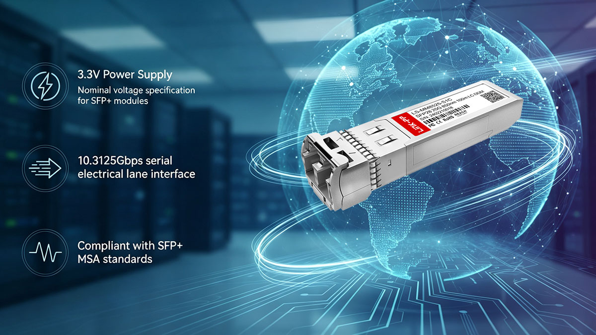
Das Juniper EX-SFP-10GE-SR wird mit einer geregelten 3.3-V-Spannungsschiene betrieben, der Standardversorgungsspannung für SFP+-Optikmodule. Diese elektrische Eingangsspannung ist präzise spezifiziert, um einen stabilen Laserbetrieb und gleichbleibende optische Ausgangseigenschaften zu gewährleisten.
Zu den wichtigsten im Datenblatt definierten Aspekten gehören:
- Nennversorgungsspannung: 3.3 V DC
- Zulässiger Toleranzbereich für einen stabilen Betrieb bei Lastschwankungen
- Interne Regelung zur Isolierung optischer Komponenten von Netzspannungsschwankungen
- Abhängigkeit der Laserstabilität von der Spannungskonstanz
Eine stabile Spannungsversorgung ist von entscheidender Bedeutung, da bereits kleine Schwankungen die VCSEL-Vorspannungsbedingungen beeinflussen können, was wiederum Auswirkungen auf die optische Ausgangsleistung und die Signalqualität bei 10-Gbit/s-Signalraten hat.
Stromverbrauch und Verlustleistung
Das aktuelle Verbrauchsprofil definiert, wie viel elektrische Leistung das Modul unter Betriebsbedingungen vom Hostsystem bezieht. Dies hat direkten Einfluss auf die thermische Auslegung und die Portdichtebeschränkungen der Switches der EX-Serie.
Typische Aspekte, die bei der Betrachtung von Datenblättern zu berücksichtigen sind:
- Typischer Betriebsstrom unter Standard-10GbE-Verkehrsbedingungen
- Maximale Stromaufnahme unter ungünstigsten Betriebsbedingungen
- Verlustleistungsverhalten bei der Umwandlung elektrischer Energie in optische Leistung und Wärme
- Skalierungseffekte in Multiport-Hochdichte-Switch-Umgebungen
Um die Auswirkungen auf Systemebene besser zu verstehen, lässt sich die Beziehung zwischen elektrischer Eingangsleistung und thermischer Ausgangsleistung wie folgt zusammenfassen:
| Parameter | Beschreibung | Auswirkungen auf das System |
|---|---|---|
| Versorgungsspannung (3.3V) | Eingangsquelle | Definiert die operative Basislinie |
| Stromaufnahme | Stromverbrauch | Ermittelt die Leistungsaufnahme pro Modul |
| Verlustleistung | Im Betrieb erzeugte Wärme | Einflüsse auf die Chassis-Kühlung |
Diese Parameter definieren gemeinsam, wie viele Module innerhalb eines vorgegebenen thermischen und Leistungsbereichs einer EX-Switch-Plattform unterstützt werden können.
Hochgeschwindigkeits-Schnittstelle (SFI/XFI)
Das Juniper EX-SFP-10GE-SR nutzt eine serielle Hochgeschwindigkeitsschnittstelle zur Kommunikation zwischen dem Host-ASIC und dem optischen Modul. Diese Schnittstelle wird typischerweise mit den Signalstandards SFI (Serial Front Interface) oder XFI implementiert, die eine Datenübertragung von 10 Gbit/s unterstützen.
Zu den wichtigsten elektrischen Eigenschaften gehören:
- Serielle Datenrate: 10.3125 Gbit/s pro Lane
- Differenzielle Signalgebung für Störfestigkeit und Signalintegrität
- Direkte Zuordnung zwischen der PHY-Schicht des Schalters und dem optischen Modulationsschaltkreis
- Strenge Anforderungen an Impedanz und Signalqualität innerhalb der Host-Leiterplatte
Auf dieser Ebene ist die Schnittstelle nicht einfach nur ein Datenkanal, sondern ein kontrollierter elektrischer Hochfrequenz-Übertragungspfad. Jegliche Impedanzfehlanpassung, Signalreflexion oder Jitter, die in dieser Phase auftreten, können die optische Ausgangsleistung und das nachgelagerte BER-Verhalten direkt beeinflussen.
🏮 Timing-, Jitter- und Signalintegritätseigenschaften
Die Timing-, Jitter- und Signalintegritätseigenschaften des Juniper EX-SFP-10GE-SR bestimmen, wie zuverlässig das Modul die Signalqualität bei hohen Geschwindigkeiten von 10 Gbit/s während der elektrisch-optischen Wandlung und Übertragung aufrechterhält. Diese Parameter sind in 10GBASE-SR-Systemen von entscheidender Bedeutung, da selbst geringfügige Timing-Abweichungen die Bitfehlerrate (BER) und die Gesamtstabilität der Verbindung direkt beeinträchtigen können.
Optische Ausbreitungsverzögerungseigenschaften
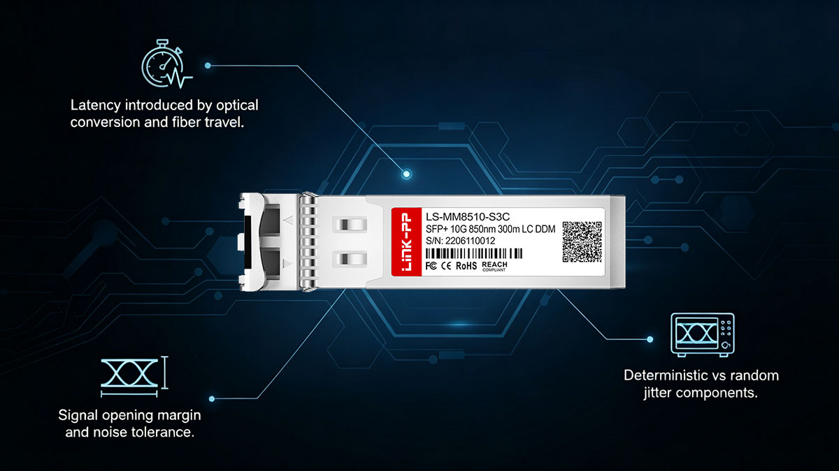
Die optische Laufzeitverzögerung beschreibt die Zeit, die ein Signal benötigt, um den Transceiver und das Glasfasermedium zu durchlaufen. Beim Juniper EX-SFP-10GE-SR wird diese Verzögerung primär durch die interne Wandlungslatenz und die Glasfaserübertragungsgeschwindigkeit bestimmt.
Zu den wichtigsten Merkmalen auf Datenblattebene gehören:
- Behobene Serialisierungs- und Deserialisierungsverzögerung innerhalb des SFP+-Moduls
- VCSEL-Modulationsansprechzeit bei einer Wellenlänge von 850 nm
- Die Faserlaufzeitverzögerung wird durch den Brechungsindex der Multimode-Faser bestimmt.
- Gesamtbeitrag zur End-to-End-Latenz in 10GbE-Verbindungen
Obwohl die Ausbreitung in Glasfasern relativ konstant ist, führt der Transceiver aufgrund der internen Signalverarbeitung zu einer deterministischen Verzögerungskomponente. Diese Verzögerung ist typischerweise gering, wird aber in latenzempfindlichen oder eng synchronisierten Netzwerkdesigns relevant.
Jitter-Performance und Compliance-Grenzwerte
Jitter bezeichnet kurzfristige Schwankungen im Signalzeitpunkt und ist ein Schlüsselparameter in optischen Hochgeschwindigkeits-Kommunikationssystemen. Der Juniper EX-SFP-10GE-SR muss innerhalb der strengen, durch den IEEE-802.3ae-Standard definierten Jitter-Grenzwerte arbeiten, um eine zuverlässige Datenwiederherstellung am Empfänger zu gewährleisten.
Wichtige Jitter-Merkmale sind:
- Deterministisches Jitterverhalten, verursacht durch Signalverarbeitung und Modulation
- Zufälliges Jitter, verursacht durch thermisches Rauschen, elektrische Interferenzen
- Einhaltung der IEEE-definierten Jittertoleranz und Ausgabemasken
- Wechselwirkung zwischen elektrischem Schnittstellenjitter (SFI/XFI) und optischer Ausgangsstabilität
In der Praxis verringert übermäßiger Jitter die Öffnung des Augendiagramms, was die Wahrscheinlichkeit von Abtastfehlern am Empfänger erhöht. Daher stellt das Datenblatt sicher, dass der Jitter von Sender und Empfänger über Temperatur- und Leistungsschwankungen hinweg innerhalb kontrollierter Grenzen bleibt.
Augendiagramm und Validierung der Signalqualität
Das Augendiagramm ist eine grundlegende Diagnosedarstellung zur Beurteilung der Signalintegrität in optischen Hochgeschwindigkeitssystemen. Beim Juniper EX-SFP-10GE-SR gewährleistet die Einhaltung der Augendiagramm-Vorgaben, dass das übertragene Signal ausreichende Zeit- und Amplitudenreserven für eine präzise Datenwiederherstellung aufweist.
Wichtige Aspekte, die beim Betrachten des Datenblatts zu berücksichtigen sind:
- Höhe und Breite der Augenöffnung als Indikatoren für die Signalstärke
- Konformität mit IEEE 10GBASE-SR Augenmaskenvorlagen
- Rauschabstand und Kontrolle der Interferenz zwischen Symbolen (ISI)
- Auswirkungen von Kanalbeeinträchtigungen wie Dispersion und Dämpfung
Ein gut ausgebildetes Augendiagramm zeigt an, dass das Modul eine hohe Signalintegrität sowohl im elektrischen als auch im optischen Bereich aufrechterhält. Ein geschlossenes Augendiagramm hingegen deutet auf eine Verschlechterung durch Jitterakkumulation, unzureichende optische Leistung oder übermäßige Kanaldämpfung hin. Daher ist die Validierung des Augendiagramms ein entscheidender Bestandteil der Leistungsüberprüfung auf Datenblattebene für 10GbE-SFP+-Transceiver.
🏮 Einhaltung von Vorschriften, Sicherheitsstandards und regulatorischen Standards
Die Konformitäts-, Sicherheits- und Regulierungsstandards des Juniper EX-SFP-10GE-SR definieren die zwingenden technischen und rechtlichen Anforderungen, die das Modul erfüllen muss, um sicher zu arbeiten und in globalen Netzwerkumgebungen interoperabel zu sein. Diese Datenblattspezifikationen gewährleisten, dass optische Leistung, elektromagnetisches Verhalten und Umweltauswirkungen international anerkannten Standards entsprechen.
Lasersicherheitsklassifizierung (IEC 60825-1 Klasse 1)
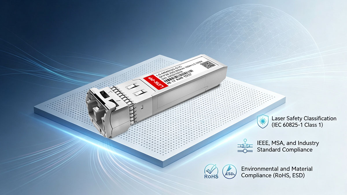
Der Juniper EX-SFP-10GE-SR ist gemäß IEC 60825-1 als Laserprodukt der Klasse 1 klassifiziert und gilt somit unter normalen Betriebsbedingungen als augensicher. Diese Klassifizierung ist eine wichtige Sicherheitsanforderung für alle optischen Transceiver auf 850-nm-VCSEL-Basis, die in Unternehmens- und Rechenzentrumsumgebungen eingesetzt werden.
Zu den wichtigsten sicherheitsrelevanten Merkmalen gehören:
- Vollständig geschlossener optischer Pfad verhindert direkte Laserbestrahlung
- Kontrollierte VCSEL-Emissionsleistung innerhalb augensicherer Grenzwerte
- Einhaltung internationaler Lasersicherheitszertifizierungsstandards
- Sicherer Betrieb im laufenden Betrieb und unter normalen Betriebsbedingungen
Diese Klassifizierung gewährleistet, dass das Modul in Umgebungen mit hoher Schaltdichte eingesetzt werden kann, ohne dass über die üblichen Handhabungspraktiken hinaus zusätzliche Laserschutzmaßnahmen erforderlich sind.
IEEE-, MSA- und Industriestandardkonformität
Die Interoperabilität und die funktionale Korrektheit des Juniper EX-SFP-10GE-SR werden durch die Einhaltung mehrerer Industriestandards sichergestellt, die sowohl die elektrische als auch die optische Leistung regeln.
Zu den wichtigsten Compliance-Rahmenwerken gehören:
- IEEE 802.3ae 10GBASE-SR-Standard für optische 10GbE-Multimode-Übertragung
- SFP+ Multi-Source Agreement (MSA) zur Definition der Konsistenz der mechanischen und elektrischen Schnittstelle
- Standardisierter optischer Wellenlängenbetrieb bei 850 nm für Kurzstreckenverbindungen
- Definierte Signalcodierung und Datenrate von 10.3125 Gbit/s
Diese Standards gewährleisten, dass sich das Modul auf kompatiblen Netzwerkgeräten vorhersehbar verhält und unabhängig von der Einsatzumgebung konsistente Leistungsmerkmale beibehält.
Umwelt- und Materialkonformität (RoHS, ESD)
Neben den elektrischen und optischen Leistungseigenschaften muss der Juniper EX-SFP-10GE-SR auch Umwelt- und Materialkonformitätsanforderungen erfüllen, um eine sichere weltweite Verteilung und langfristige Zuverlässigkeit zu gewährleisten.
Zu den wichtigsten regulatorischen und umweltbezogenen Merkmalen gehören:
- RoHS-Konformität beschränkt die Verwendung gefährlicher Stoffe wie Blei und Quecksilber
- Design mit Schutz vor elektrostatischer Entladung (ESD) zur Vermeidung von Schäden bei Handhabung und Installation
- Die definierten Betriebs- und Lagertemperatur- und Feuchtigkeitsbereiche sind in den Datenblättern angegeben.
- Materialkonformität gewährleistet langfristige mechanische und chemische Stabilität
Zusammenfassend die wichtigsten Compliance-Kategorien und ihre Auswirkungen auf das System:
| Compliance-Kategorie | Norm / Anforderung | Zweck auf Systemebene |
|---|---|---|
| Lasersicherheit | IEC 60825-1 Klasse 1 | Gewährleistet augensicheren Betrieb |
| Ethernet-Standard | IEEE 802.3ae | Gewährleistet Protokollkompatibilität |
| Formfaktor | SFP+ MSA | Gewährleistet die mechanische und elektrische Interoperabilität |
| Environmental | RoHS- und ESD-Schutz | Gewährleistet Sicherheit und Einhaltung der globalen Einsatzbestimmungen |
Diese kombinierten Compliance-Anforderungen gewährleisten, dass der Juniper EX-SFP-10GE-SR sicher in Unternehmens-, Netzbetreiber- und Rechenzentrumsumgebungen eingesetzt werden kann und dabei eine gleichbleibende Leistung und regulatorische Konformität weltweit gewährleistet ist.
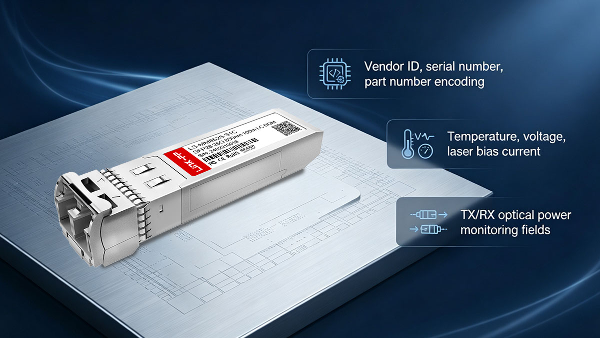
🏮 EEPROM-Speicher und digitale Diagnose (DOM-Architektur)
Die EEPROM-Speicher- und digitale Diagnosearchitektur des Juniper EX-SFP-10GE-SR definiert, wie das Modul Identifikationsdaten speichert und Betriebszustände in Echtzeit meldet. Diese im Datenblatt beschriebenen Merkmale ermöglichen es Hostsystemen, den Transceiver zu erkennen, die Kompatibilität zu überprüfen und die optische Leistung während des Betriebs kontinuierlich zu überwachen.
Modulidentifikation und EEPROM-Datenstruktur
Der EEPROM-Speicher des Juniper EX-SFP-10GE-SR enthält standardisierte Identifikationsdaten, die es Switches der Juniper EX-Serie ermöglichen, das Modul automatisch zu erkennen und zu klassifizieren. Diese Informationen sind für die Systeminventarverwaltung und die Schnittstelleninitialisierung unerlässlich.
Zu den wichtigsten EEPROM-Merkmalen gehören:
- Herstelleridentifikationsdaten (Modulhersteller und Kompatibilitätsfelder)
- Teilenummer und Revisionsinformationen zur genauen Modulklassifizierung
- Eindeutige Seriennummer zur Rückverfolgbarkeit und Lebenszyklusverwaltung
- Standardmäßige SFP+-Speicherbelegungsstruktur, definiert durch die MSA-Spezifikation
Diese Felder werden vom Hostsystem während der Initialisierung ausgelesen und ermöglichen so die automatische Konfiguration der optischen Schnittstelle ohne manuellen Eingriff. Die EEPROM-Struktur stellt außerdem sicher, dass die Systemfirmware überprüfen kann, ob das Modul mit den unterstützten Betriebsparametern übereinstimmt.
Digitales Diagnosemonitoring (DDM/DOM-Parameter)
Die digitale Diagnoseüberwachung (DDM), auch als digitale optische Überwachung (DOM) bezeichnet, liefert Echtzeit-Telemetriedaten wichtiger optischer und elektrischer Betriebszustände. Das Juniper EX-SFP-10GE-SR nutzt diese Parameter, um den Zustand und die Leistungsstabilität des Moduls im laufenden Netzwerkbetrieb zu melden.
Zusammenfassend die wichtigsten DOM-Parameter und ihre technische Bedeutung:
| Parameter | Messwert | Technischer Zweck |
|---|---|---|
| Temperatur | Thermischer Zustand des internen Moduls | Erkennt Überhitzungszustände |
| Stromspannung | 3.3-V-Versorgungsstabilität | Gewährleistet die elektrische Integrität |
| Ruhestrom | VCSEL-Antriebszustand | Zeigt den Zustand des Lasers an |
| Sendeleistung | Optische Ausgangsstärke | Überprüft die Übertragungsleistung |
| Rx-Leistung | Eingangssignalpegel | Bestätigt die Verbindungsqualität |
Diese Diagnoseparameter bilden die Grundlage für die kontinuierliche Validierung der optischen Verbindung und ermöglichen es dem System, einen stabilen 10GbE-Betrieb aufrechtzuerhalten, indem Leistungsabweichungen erkannt werden, bevor sie die Datenübertragung beeinträchtigen.
Kalibrierungsdaten und Werksprogrammierung
Die im EEPROM gespeicherten Kalibrierungs- und Werksprogrammierungsdaten gewährleisten, dass jedes Juniper EX-SFP-10GE-SR-Modul innerhalb eng definierter Leistungstoleranzen arbeitet. Diese Daten werden während der Fertigung festgelegt und sind unerlässlich für ein konsistentes optisches Verhalten der verschiedenen Module.
Zu den wichtigsten Merkmalen gehören:
- Werkseitig kalibrierte optische Leistungsreferenzwerte für die Sende- und Empfangskanäle
- Kompensationsparameter für temperaturabhängige Leistungsschwankungen
- Voreingestellte Schwellenwerte für DOM-Alarm- und Warnzustände
- Modulspezifische Korrekturfaktoren zur Aufrechterhaltung der Messgenauigkeit
Diese Kalibrierungswerte ermöglichen dem Modul eine gleichbleibende Leistungsberichterstattung über den gesamten Betriebsbereich. Dadurch kann sich das Hostsystem bei der Bewertung der Verbindungsqualität auf präzise Diagnosewerte verlassen und sicherstellen, dass sowohl die optische Ausgangsleistung als auch die Empfängerempfindlichkeit während der gesamten Lebensdauer des Moduls innerhalb der im Datenblatt definierten Grenzen bleiben.
🏮 Modell der thermischen Eigenschaften und der Verlustleistung
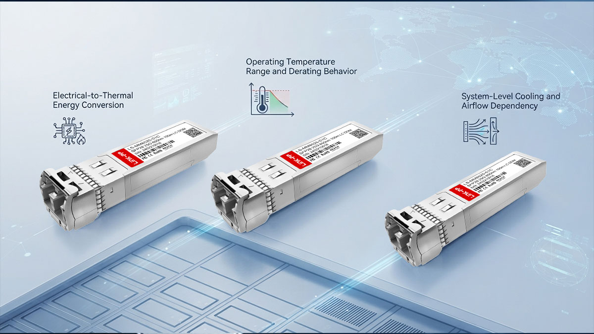
Die thermischen Eigenschaften und das Verlustleistungsmodell des Juniper EX-SFP-10GE-SR beschreiben, wie elektrische Energie im Betrieb in Wärme umgewandelt und diese Wärme in Umgebungen mit hoher Switchdichte abgeführt wird. Diese Datenblattparameter sind entscheidend für eine stabile optische Leistung, da die Temperatur die VCSEL-Effizienz, die Empfängerempfindlichkeit und die gesamte Signalintegrität direkt beeinflusst.
Umwandlung von elektrischer in thermische Energie
Der Juniper EX-SFP-10GE-SR gibt im Normalbetrieb einen Teil seiner elektrischen Eingangsleistung als Wärme ab. Diese Wärmeabgabe ist eine direkte Folge der internen Laseransteuerschaltungen, der Signalaufbereitungslogik und der Hochgeschwindigkeits-Wandlungsprozesse von elektrisch zu optisch.
Zu den wichtigsten Merkmalen auf Datenblattebene gehören:
- Umwandlung von 3.3 V elektrischer Eingangsspannung in optische Ausgangsspannung und thermische Verluste
- Wärmeerzeugung hauptsächlich durch VCSEL-Treiber- und Steuerschaltungen
- Erhöhte Wärmeabgabe unter dauerhafter Übertragungslast von 10 Gbit/s
- Abhängigkeit der Verlustleistung vom Verkehrsaufkommen und der Signalaktivität
In der Praxis fungiert das Modul als lokale Wärmequelle innerhalb des Switch-Gehäuses. Bei der Verwendung mehrerer SFP+-Module in Konfigurationen mit hoher Packungsdichte wird die kumulative Wärmeentwicklung zu einem wichtigen Faktor für die thermische Systemplanung.
Betriebstemperaturbereich und Derating-Verhalten
Der Betriebstemperaturbereich definiert die Umgebungsbedingungen, innerhalb derer der Juniper EX-SFP-10GE-SR seine optischen und elektrischen Spezifikationen vollständig erfüllt. Außerhalb dieser Grenzen kann es zu Leistungseinbußen oder Schutzmechanismen kommen.
Typische Aspekte, die bei der Betrachtung von Datenblättern zu berücksichtigen sind:
- Definierte minimale und maximale Betriebstemperaturschwellenwerte
- Stabiles optisches Ausgangsverhalten unter Standardumgebungsbedingungen
- Allmähliche Leistungsverschlechterung unter erhöhter Temperaturbelastung
- Temperaturabhängige Variation der Sendeleistung und der Empfängerempfindlichkeit
Um das thermische Einwirkungsverhalten besser zu veranschaulichen, lässt sich der Zusammenhang zwischen Temperatur und Leistung wie folgt zusammenfassen:
| Temperaturbedingung | Optisches Verhalten | Auswirkungen auf das System |
|---|---|---|
| Normaler Betriebsbereich | Stabile Sende-/Empfangsleistung | Vollständige Linkkonformität |
| Erhöhte Temperatur | Reduzierter optischer Rand | Erhöhtes BER-Risiko |
| Nahezu maximalem Limit | Spürbare Leistungsveränderung | Mögliche Verbindungsinstabilität |
Diese Eigenschaften gewährleisten, dass Systementwickler bei der Installation mehrerer Module in beengten oder stark ausgelasteten Switch-Umgebungen thermische Reserven berücksichtigen.
Systemweite Kühlung und Abhängigkeit vom Luftstrom
Die thermische Leistung des Juniper EX-SFP-10GE-SR hängt nicht nur vom Modul selbst ab, sondern auch von der Luftstromführung und der Kühlarchitektur des Host-Switches. Eine adäquate Wärmeableitung gewährleistet, dass die optischen und elektrischen Parameter innerhalb der im Datenblatt angegebenen Grenzen bleiben.
Zu den wichtigsten thermischen Aspekten auf Systemebene gehören:
- Luftstrommuster von vorne nach hinten oder von Seite zu Seite im Chassis der EX-Serie
- Einfluss der Portdichte auf die lokale Wärmeansammlung
- Wechselwirkung zwischen benachbarten SFP+-Modulen in dichten Konfigurationen
- Abhängigkeit von der Gehäuselüfterdrehzahl und den Wärmeregelungsstrategien
Bei Installationen mit hoher Dichte ist die Effizienz der Luftzirkulation ein entscheidender Faktor für die Aufrechterhaltung einer stabilen optischen Ausgangsleistung und Empfängerempfindlichkeit. Unzureichende Kühlung kann zu thermischer Drift führen, wodurch die Verbindungsreserve verringert und die Fehlerraten erhöht werden können.
🏮 Fazit
Der Juniper EX-SFP-10GE-SR Transceiver ist ein 10GBASE-SR-konformes SFP+-Modul für die Kurzstrecken-Multimode-Glasfaserübertragung bei 850 nm. Sein Datenblatt definiert alle optischen, elektrischen, mechanischen, thermischen und Konformitätsparameter, die die Systemleistung bestimmen. Als Referenzmodell legt es strenge Grenzwerte für Leistungsaufnahme, Empfängerempfindlichkeit, Jittertoleranz und DOM-Überwachungsgenauigkeit fest und gewährleistet so ein vorhersehbares 10GbE-Verhalten in Unternehmens- und Rechenzentrumsumgebungen.
Die wichtigsten technischen Erkenntnisse aus dem Datenblatt des Juniper EX-SFP-10GE-SR lassen sich wie folgt zusammenfassen:
- Die optische Leistung wird durch die Sendeleistung, die Empfangsempfindlichkeit und die Linkbudgetbeschränkungen definiert.
- Das elektrische Verhalten wird durch eine 3.3-V-Stromschiene und eine 10.3125-Gbit/s-SFI/XFI-Schnittstelle bestimmt.
- Die Signalintegrität hängt von kontrolliertem Jitter, Einhaltung des Augendiagramms und BER-Stabilität ab.
- Die mechanische Konstruktion entspricht dem standardisierten SFP+-Formfaktor mit LC-Duplex-Optikausrichtung.
- Thermische Leistung und Verlustleistung beeinflussen direkt die Einsatzdichte und Stabilität.
- Die Einhaltung von IEEE 802.3ae, SFP+ MSA und IEC-Lasersicherheit gewährleistet globale Interoperabilität
Diese Parameter definieren das Modul gemeinsam als eine vollständig spezifizierte Komponente der physikalischen Schicht und nicht als eine konfigurierbare Netzwerkfunktion, weshalb die Interpretation des Datenblatts für die korrekte Systemauslegung unerlässlich ist.
Ein umfassendes Verständnis des Juniper EX-SFP-10GE-SR-Datenblatts ermöglicht es Ingenieuren, die Machbarkeit von Verbindungen präzise zu bewerten, optische Leistungsmargen vorherzusagen und die Konformität bei komplexen 10GbE-Implementierungen sicherzustellen. Für Organisationen, die zusätzliche Spezifikationen für optische Transceiver, Kompatibilitätsreferenzen und erweiterte technische Dokumentationsressourcen benötigen, bietet das Datenblatt weitere Informationen. LINK-PP Offizieller Shop bietet eine strukturierte Plattform zur Erforschung einer breiten Palette standardisierter optischer Verbindungslösungen, die den Anforderungen moderner Netzwerke entsprechen.