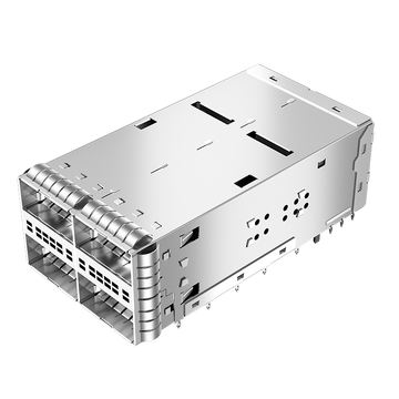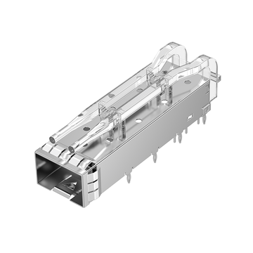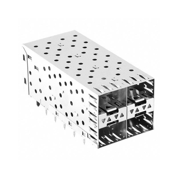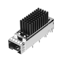
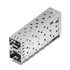
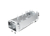
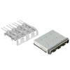

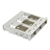

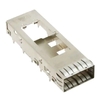
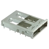
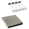
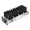





Controlling the bill of materials (BOM) is an ongoing challenge for networking hardware manufacturers. Even relatively small components, such as SFP+ cages, can contribute significantly to total production expenses when equipment is manufactured in large quantities. Reducing component costs without compromising mechanical reliability, electromagnetic interference (EMI) protection, or production stability is therefore an important part of hardware cost optimization.
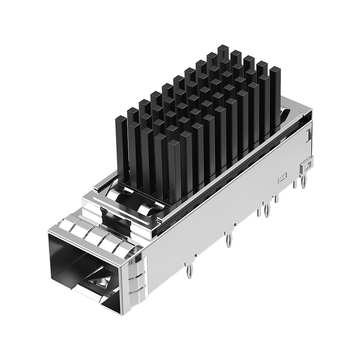
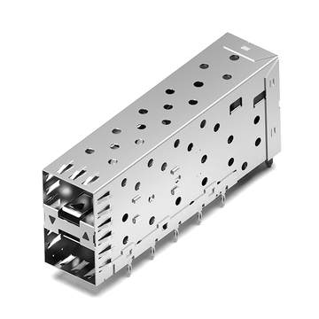
The TE Connectivity 2007198-1 is a 16Gb/s, 1×1 SFP+ cage assembly featuring through-hole press-fit mounting and EMI springs. Although it serves as a standard interface component in networking equipment, its unit cost and sourcing requirements can affect the overall BOM. For manufacturers looking to control these expenses, evaluating a compatible alternative may be more practical than changing an established PCB design.
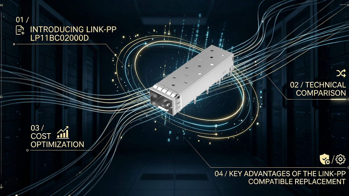
In this guide, we examine how to reduce 2007198-1 BOM costs by evaluating the LINK-PP LP11BC02000D SFP+ cage as an alternative component. The discussion covers:
-
The technical characteristics and cost implications of the original 2007198-1.
-
The specifications and potential advantages of the LINK-PP's SFP+ Cage.
-
PCB footprint, press-fit, mechanical, and EMI compatibility checks.
-
Prototype validation, production qualification, and cost-saving calculations.
By understanding these factors, engineering and sourcing teams can determine whether an alternative SFP+ cage can support their existing hardware platform without unnecessary PCB redesign expenses.
Understanding the TE Connectivity 2007198-1 SFP+ Cage
The TE Connectivity 2007198-1 is a single-port SFP+ cage assembly designed for high-speed pluggable I/O applications. It provides the mechanical enclosure, module guidance, and EMI containment required for an SFP+ transceiver interface. Understanding its construction and specifications is the first step toward evaluating compatible replacements.
What Is the TE 2007198-1?
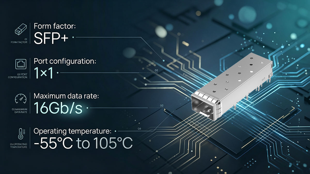
The 2007198-1 is a 1×1 SFP+ cage assembly manufactured by TE Connectivity. It is designed to accommodate SFP+ transceivers and uses a through-hole press-fit termination structure to secure the cage to the PCB.
Unlike an optical transceiver, the cage does not perform optical-to-electrical signal conversion. Instead, it provides the physical interface and shielding structure surrounding the pluggable module.
Its primary functions include:
-
Mechanical support: Holds the SFP+ module in the correct position and provides structural support during insertion and removal.
-
Module alignment: Guides the transceiver into the mating connector on the PCB.
-
EMI containment: Uses internal and external EMI springs to establish shielding contact with surrounding conductive structures.
-
PCB attachment: Uses press-fit termination posts to establish mechanical attachment without conventional soldering of the cage terminals.
The 2007198-1 is intended for SFP+ applications, including networking equipment such as switches, routers, servers, and telecommunications hardware. Its single-port configuration makes it suitable for PCB layouts requiring an individual SFP+ interface.
Key Technical Specifications of 2007198-1
The TE 2007198-1 combines a 1×1 SFP+ configuration, 16Gb/s maximum data-rate rating, and press-fit PCB termination. These characteristics are important when identifying a replacement because they define the basic mechanical interface and intended application.
The following table summarizes its principal specifications.
| Parameter | TE 2007198-1 Specification |
|---|---|
| Manufacturer | TE Connectivity |
| Part Number | 2007198-1 |
| Product Type | SFP+ Cage |
| Port Configuration | 1×1 |
| Maximum Data Rate | 16Gb/s |
| PCB Termination | Through-Hole Press-Fit |
| Termination Post Length | 2.05mm |
| Cage Material | Nickel Silver |
| EMI Containment | Internal/External EMI Springs |
| Lightpipe | Not Included |
| Recommended PCB Thickness | 2.25mm |
| Operating Temperature | -55°C to 105°C |
| Packaging | Tray |
Several specifications deserve particular attention during replacement evaluation.
-
Press-fit termination: The mounting structure must match the existing PCB hole pattern and the applicable press-fit requirements.
-
EMI spring configuration: Grounding contact positions and shielding performance must be verified in the assembled enclosure.
-
PCB thickness: The board thickness and mechanical tolerances must be compatible with the cage's termination structure.
-
Temperature rating: The replacement must meet the environmental requirements of the final equipment.
These parameters provide a starting point for identifying an alternative, but the manufacturer's mechanical drawing and application specification should remain the primary references for PCB design and assembly decisions.
Why 2007198-1 Matters in 16G SFP+ Hardware Design
The 2007198-1 matters because its mechanical structure directly affects how an SFP+ module interfaces with the PCB, connector, and equipment enclosure. A suitable cage helps maintain consistent module positioning, mechanical retention, and EMI grounding.
In a typical SFP+ interface, the cage works together with several other components:
-
SFP+ SMT connector mounted on the PCB.
-
Press-fit cage assembly surrounding the connector.
-
Chassis or front-panel grounding structure.
-
SFP+ optical or copper transceiver.
-
Optional lightpipe or status-indicator assembly, where required by the system design.
The cage and connector must be correctly positioned relative to one another. Even a small mechanical mismatch can affect module insertion, front-panel alignment, or EMI contact.
For this reason, replacing a 2007198-1 should involve more than comparing the external dimensions. Engineers should evaluate the complete mechanical interface and verify the assembled configuration before production adoption.
Why 2007198-1 Can Increase Your BOM Costs
The 2007198-1 can contribute to BOM cost pressure because its unit price is multiplied across every SFP+ port and every manufactured device. In addition to the component price, sourcing conditions, inventory requirements, and qualification expenses can influence the total cost of using this cage in production.
The Impact of Unit Pricing on Total BOM Cost
A small difference in the unit cost of an SFP+ cage can become substantial when production volumes increase. This is particularly relevant for networking hardware with multiple SFP+ ports per device.
Consider a switch containing eight SFP+ interfaces. If the manufacturer produces 5,000 units annually, the total cage requirement is:
8 ports × 5,000 switches = 40,000 SFP+ cages.
Even a modest reduction in the component cost can produce measurable annual savings.
The basic calculation is:
Annual Component Savings = (Original Unit Cost − Alternative Unit Cost) × Annual Quantity
For example, assume the following hypothetical pricing:
-
Original 2007198-1 unit cost: A$ 4.41.
-
Alternative SFP+ cage unit cost: A$ 3.53.
-
Annual quantity: 40,000 units.
The resulting savings would be:
(A$ 4.41 − A$ 3.53) × 40,000 = A$ 35.28,000.
This example illustrates why component-level optimization deserves attention even when the individual part appears inexpensive.
Actual savings depend on quoted prices, order quantities, shipping, qualification expenses, and other commercial conditions. The objective is to identify a technically suitable alternative that reduces the total component cost without creating additional production expenses.
Hidden Costs Beyond the Component Price
The unit price is only one part of the total cost associated with a component. Supply availability, inventory management, and supplier coordination can also influence the overall BOM expense.
When reviewing the 2007198-1 sourcing structure, manufacturers should consider:
-
Inventory carrying costs: Maintaining sufficient component inventory requires working capital and storage capacity.
-
Supplier coordination: Multiple sourcing channels may involve additional communication, documentation, and quality-management work.
-
Lead-time uncertainty: Component shortages can interrupt assembly schedules and delay equipment delivery.
-
Production interruptions: Missing cage assemblies can prevent otherwise complete PCB assemblies from moving through manufacturing.
-
Qualification expenses: Introducing an alternative requires engineering review, prototype testing, and production approval.
These indirect expenses can become particularly important for high-volume networking equipment manufacturers.
A compatible alternative can provide another sourcing option, but its actual financial value should be assessed alongside supply consistency, documentation quality, and production readiness.
Why a PCB Redesign Can Offset Component Savings
A PCB redesign can introduce expenses that outweigh the expected savings from a lower-cost cage. Changing a press-fit cage may require modifications to the PCB footprint, mechanical positioning, grounding connections, and surrounding enclosure structure.
Potential redesign expenses include:
-
PCB layout engineering and design review.
-
New PCB fabrication and prototype assembly.
-
Drill-hole and plating adjustments.
-
Mechanical fit testing and enclosure verification.
-
EMI testing and qualification.
-
Production documentation updates.
-
Additional engineering approval and manufacturing validation.
These activities can increase both development costs and time to production.
For an established networking hardware platform, retaining the existing PCB layout is often a more efficient approach when a compatible alternative can satisfy the original mechanical and environmental requirements.
This is why we recommend evaluating the LINK-PP LP11BC02000D against the existing 2007198-1 installation before considering a PCB redesign. The key is to establish whether the alternative fits the existing design through drawing comparison and physical validation, rather than assuming that similar product descriptions guarantee interchangeability.
LINK-PP LP11BC02000D: A Compatible Alternative to 2007198-1
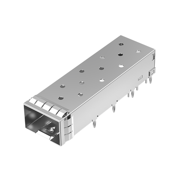
LINK-PP offers the LP11BC02000D as a compatible alternative to the TE Connectivity 2007198-1. It is a 1×1 SFP+ cage featuring through-hole press-fit mounting and EMI springs, providing manufacturers with another component option for evaluating BOM cost reduction while retaining their existing PCB architecture.
Introducing LINK-PP LP11BC02000D
The LINK-PP LP11BC02000D is designed for 16Gb/s SFP+ applications requiring a single-port cage assembly with press-fit PCB mounting.
Its product configuration makes it relevant to manufacturers currently using the TE 2007198-1 and looking for an alternative sourcing option.
Key characteristics include:
-
Product type: SFP+ cage assembly.
-
Port configuration: 1×1.
-
Maximum data-rate rating: 16Gb/s.
-
PCB mounting: Through-hole, right-angle press-fit.
-
EMI containment: EMI springs.
-
Cage material: Copper alloy with nickel plating.
-
Lightpipe: Not included.
-
Operating temperature: -55°C to 85°C.
-
Packaging: Tray.
The LP11BC02000D is intended for applications such as data center switches, routers, telecommunications equipment, and other networking systems using SFP+ interfaces.
For existing 2007198-1 designs, its press-fit mounting configuration and single-port SFP+ structure make it a candidate for replacement evaluation. Engineers should still verify the detailed drawings, mounting dimensions, and environmental requirements before approving it for production.
2007198-1 vs. LINK-PP LP11BC02000D: Technical Comparison
The two models share several important application characteristics, including their 1×1 SFP+ configuration, 16Gb/s rating, press-fit mounting, and EMI spring containment. However, their published material and operating-temperature specifications are not identical.
The following comparison highlights the principal differences and matching characteristics.
| Technical Parameter | TE 2007198-1 | LINK-PP LP11BC02000D |
|---|---|---|
| Manufacturer | TE Connectivity | LINK-PP |
| Product Type | SFP+ Cage | SFP+ Cage |
| Port Configuration | 1×1 | 1×1 |
| Maximum Data Rate | 16Gb/s | 16Gb/s |
| PCB Mounting | Through-Hole Press-Fit | Through-Hole Press-Fit |
| EMI Containment | Internal/External EMI Springs | EMI Springs |
| Cage Material | Nickel Silver | Copper Alloy, Nickel-Plated |
| Lightpipe | Not Included | Not Included |
| Operating Temperature | -55°C to 105°C | -55°C to 85°C |
| Published Dimensions | Refer to TE Drawing | 48.70 × 14.25 × 9.75mm |
The comparison reveals several points that matter for replacement decisions.
Matching characteristics:
-
Both models are designed for single-port SFP+ applications.
-
Both have a maximum data-rate rating of 16Gb/s.
-
Both use through-hole press-fit PCB mounting.
-
Both provide EMI spring containment.
-
Neither model includes a lightpipe.
Specifications requiring additional attention:
-
The published operating-temperature range of the LINK-PP model ends at 85°C, compared with 105°C for the TE model.
-
The listed cage materials differ.
-
EMI spring geometry and grounding contact locations require drawing-level comparison.
-
The published external dimensions should not be treated as proof that all mounting coordinates and tolerances match.
For applications operating within the LP11BC02000D temperature range, the alternative may be suitable for further engineering qualification. Equipment requiring operation above 85°C needs a different qualification decision.
How LINK-PP Helps Reduce 2007198-1 BOM Costs
LINK-PP provides the LP11BC02000D as an alternative to the TE 2007198-1, giving networking hardware manufacturers another option when reviewing SFP+ cage costs.
The potential cost benefits include:
-
Alternative component pricing: Competitive pricing provides an opportunity to reduce per-port cage expenses.
-
Existing PCB design evaluation: Its 1×1 press-fit SFP+ configuration supports evaluation within established PCB layouts.
-
Sourcing flexibility: An additional component source can help manufacturers diversify their supply arrangements.
-
Volume cost optimization: Per-unit price differences can translate into meaningful savings across large production quantities.
-
Reduced redesign exposure: If mechanical and assembly compatibility is verified, manufacturers may avoid unnecessary PCB layout modifications.
At LINK-PP, we focus on providing compatible interconnection components for networking hardware applications. Our LP11BC02000D offers an additional option for manufacturers seeking to optimize their SFP+ cage BOM while maintaining a familiar press-fit interface.
The actual cost advantage should be established through a project-specific quotation that considers volume, delivery requirements, and qualification costs.
Key Advantages of the LINK-PP Compatible Replacement
The LP11BC02000D offers several practical advantages for manufacturers evaluating a 2007198-1 alternative. Its value lies in providing another SFP+ cage option with a familiar mounting concept and a potentially more competitive cost structure.
Its main advantages include:
-
BOM cost optimization: Provides an alternative component for evaluating lower SFP+ cage expenditure.
-
Existing design continuity: Its 1×1 press-fit configuration supports mechanical compatibility evaluation against existing PCB layouts.
-
Production flexibility: Offers an additional sourcing option for networking hardware manufacturers.
-
SFP+ application suitability: Supports the same stated 16Gb/s application rating.
-
Technical documentation: Product specifications and drawings can support engineering comparison and qualification.
-
Supply-chain diversification: Helps manufacturers evaluate an alternative source rather than depending exclusively on one component supplier.
These benefits make the LP11BC02000D worth considering in cost-reduction projects. However, a successful replacement must satisfy the actual mechanical, environmental, and production requirements of the target equipment.
Can You Replace 2007198-1 Without Redesigning Your PCB?
Replacing the 2007198-1 without redesigning the PCB may be possible when the alternative cage matches the existing mounting interface, mechanical envelope, grounding arrangement, and assembly requirements. The LINK-PP LP11BC02000D is a candidate for this evaluation, but a matching port configuration and termination type alone do not establish a guaranteed drop-in replacement.
Matching the Existing PCB Footprint and Press-Fit Structure
The most important requirement for avoiding PCB redesign is verifying that the alternative cage can use the existing PCB mounting pattern.
A press-fit cage relies on carefully controlled mechanical interference between its termination posts and plated through-holes. Differences in hole dimensions, pin geometry, or plating specifications can affect insertion force, retention, and PCB integrity.
Before approving the LP11BC02000D, compare the following:
-
Press-fit termination locations and pin arrangement.
-
Termination post dimensions and tolerances.
-
Recommended drill-hole diameters.
-
PCB hole plating thickness and requirements.
-
PCB thickness and mechanical support conditions.
-
Cage mounting position relative to the SFP+ connector.
-
Overall mechanical dimensions and mounting reference points.
The comparison should use the original TE product drawing and the latest LINK-PP LP11BC02000D drawing.
A similar external shape is not enough. The actual press-fit interface must be compatible with the existing PCB fabrication specifications.
If the mounting coordinates, hole requirements, and mechanical tolerances are confirmed to match, the existing PCB may be retained without modifying its footprint.
Checking Mechanical Fit and SFP+ Module Alignment
Mechanical compatibility is another essential requirement because the cage must align correctly with the SFP+ connector and the equipment front panel.
A cage that fits the PCB but does not align with the front-panel opening can create problems during module insertion and removal.
The mechanical evaluation should cover:
-
Front-panel alignment: Confirm that the cage opening aligns with the existing chassis aperture.
-
Connector positioning: Verify the relative position between the cage and SFP+ SMT connector.
-
Insertion depth: Check that the module reaches the correct mating position.
-
Retention features: Verify that the transceiver can be securely inserted and removed.
-
Component clearance: Inspect nearby PCB components, heat-generating devices, and mechanical structures.
-
Enclosure compatibility: Confirm that the replacement does not interfere with the existing chassis or shielding structure.
Prototype assembly is particularly useful for checking these details. A physical sample can reveal mechanical interference that may not be obvious from a two-dimensional footprint comparison.
When the replacement maintains the required module alignment and enclosure clearance, it can help preserve the original mechanical design.
Verifying EMI Shielding and Grounding Performance
EMI shielding must be verified because the cage forms part of the electromagnetic containment structure surrounding the SFP+ module.
Both the TE 2007198-1 and LINK-PP LP11BC02000D specify EMI spring containment. However, this shared feature does not automatically establish identical shielding performance.
Engineers should inspect:
-
Internal and external EMI spring positions.
-
Contact geometry and spring pressure.
-
Grounding contact locations.
-
Cage-to-chassis electrical continuity.
-
PCB chassis-ground connections.
-
Contact reliability after repeated module insertion and removal.
The grounding arrangement is particularly important in dense networking equipment, where multiple high-speed interfaces operate close together.
After mechanical installation, the assembled system should undergo appropriate grounding and EMI verification. Testing should follow the equipment's applicable EMC requirements and system-level qualification procedures.
A replacement should not be approved solely because its product description includes EMI springs.
When a PCB Redesign Is Not Necessary—and When It May Be
A PCB redesign may not be necessary if the LP11BC02000D satisfies the original mechanical interface and assembly requirements. The decision depends on engineering verification rather than the part-number cross-reference alone.
A replacement evaluation is more favorable when:
-
The existing press-fit hole pattern matches the alternative cage.
-
The termination posts meet the PCB hole and plating requirements.
-
The overall cage dimensions provide sufficient clearance.
-
The SFP+ connector and front-panel alignment remain unchanged.
-
Grounding and EMI requirements are satisfied.
-
The operating-temperature range meets the equipment specification.
However, a redesign or another alternative may be necessary when:
-
The press-fit hole pattern does not match.
-
Termination post geometry is incompatible.
-
The cage interferes with nearby components or the enclosure.
-
Grounding contact locations cannot be accommodated.
-
The application requires operation above the LP11BC02000D's 85°C maximum rating.
-
Mechanical or EMI qualification results do not meet the system requirements.
The most practical approach is to verify the existing PCB against the alternative's mechanical documentation before initiating layout changes. This helps avoid unnecessary redesign work while maintaining engineering control over the replacement process.
A Practical Validation Checklist Before Replacing 2007198-1
A successful 2007198-1 replacement requires drawing comparison, environmental review, prototype assembly, and production qualification. Following a consistent validation process helps manufacturers identify incompatibilities early and reduce the risk of production problems.
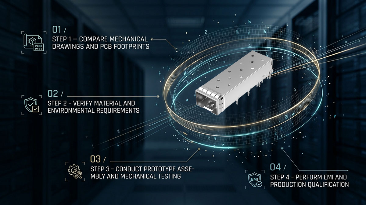
Step 1 – Compare Mechanical Drawings and PCB Footprints
The first step is to compare the original and alternative product drawings. This establishes whether the LP11BC02000D can physically fit the existing PCB design.
The engineering review should include:
-
Obtain the latest TE 2007198-1 mechanical drawing.
-
Obtain the latest LINK-PP LP11BC02000D product drawing.
-
Compare cage length, width, and height.
-
Check mounting-point coordinates.
-
Compare press-fit termination positions.
-
Verify drill-hole diameters and tolerances.
-
Review PCB thickness and plating requirements.
-
Check the cage-to-connector positioning.
The comparison should be documented so that engineering teams can identify any dimensional differences before sample assembly.
If the mounting interface is compatible, the existing PCB footprint can proceed to physical validation without an immediate layout change.
Step 2 – Verify Material and Environmental Requirements
The second step is to determine whether the alternative meets the actual environmental and material requirements of the equipment.
The two models have different published cage material and temperature specifications. These differences must be considered rather than overlooked during the cross-reference process.
The review should cover:
-
Cage material and surface finish.
-
Operating-temperature limits.
-
Relevant RoHS and REACH compliance documentation.
-
Corrosion and environmental requirements.
-
Mechanical durability expectations.
-
Applicable product qualification standards.
The temperature difference deserves particular attention. The TE 2007198-1 is rated from -55°C to 105°C, while the LINK-PP LP11BC02000D is rated from -55°C to 85°C.
Therefore, the LP11BC02000D should only be considered for applications whose operating requirements fall within its specified range.
Step 3 – Conduct Prototype Assembly and Mechanical Testing
Prototype assembly helps verify whether the replacement works with the existing PCB and enclosure under real assembly conditions.
A recommended evaluation includes:
-
Install the LP11BC02000D on an existing PCB sample.
-
Inspect the press-fit insertion process.
-
Check for PCB deformation or damage.
-
Verify cage retention and mechanical stability.
-
Insert and remove representative SFP+ modules.
-
Inspect front-panel alignment and enclosure clearance.
-
Record any mechanical interference or abnormal insertion behavior.
The prototype should use representative PCB materials, hole plating, and assembly processes.
Successful installation is an important qualification milestone, but it should not replace the remaining electrical, grounding, and system-level checks.
Step 4 – Perform EMI and Production Qualification
The final validation stage is to confirm that the alternative cage performs reliably within the intended hardware platform.
Depending on the application, testing may include:
-
Grounding continuity measurement.
-
EMI shielding and system-level EMC testing.
-
Mechanical retention verification.
-
Repeated SFP+ module insertion and removal.
-
Environmental testing within the specified operating range.
-
Production assembly process evaluation.
-
Incoming quality inspection.
Once the replacement passes the required tests, engineering teams should update the approved component list, qualification records, and manufacturing documentation.
This ensures that the alternative is introduced through a controlled engineering process rather than an informal component substitution.
Calculating the ROI of Switching to a Compatible SFP+ Cage
The ROI of replacing the 2007198-1 depends on the difference in component cost, annual production quantity, qualification expenses, and any additional supply-chain costs. A complete evaluation should consider both direct BOM savings and the costs of introducing the alternative.
Calculate Direct BOM Savings
The first step is to calculate the unit price difference between the original cage and the LINK-PP LP11BC02000D.
The basic formula is:
Annual Direct Savings = (Original Unit Price − Alternative Unit Price) × Annual Quantity
Consider the following hypothetical production scenario:
| Cost Item | Original 2007198-1 | LINK-PP LP11BC02000D |
|---|---|---|
| Assumed Unit Cost | A$ 4.41 | A$ 3.53 |
| Annual Quantity | 40,000 | 40,000 |
| Annual Component Cost | A$ 176.40,000 | A$ 141.12,000 |
| Potential Annual Savings | — | A$ 35.28,000 |
In this example, switching to the alternative reduces the annual component expenditure by A$ 35.28,000, assuming the quoted prices and required quantities remain unchanged.
The savings can increase with higher production volumes, particularly for equipment containing multiple SFP+ ports.
For a real project, manufacturers should replace these hypothetical figures with current supplier quotations and include applicable shipping and commercial terms.
Include Engineering and Qualification Costs
Direct component savings do not represent the entire financial impact of a replacement.
Introducing a new SFP+ cage may require engineering resources and validation expenses before production approval.
Typical costs include:
-
Mechanical drawing comparison.
-
Engineering evaluation and documentation.
-
Prototype PCB assembly.
-
Mechanical fit testing.
-
EMI and grounding verification.
-
Environmental qualification.
-
Manufacturing process validation.
For example, assume the qualification process costs A$ 5.88,000 and the alternative provides a unit cost reduction of A$ 0.88.
The break-even quantity is:
A$ 5.88,000 ÷ A$ 0.88 = 6,667 units (approximately).
After approximately 6,667 qualified units, the direct component savings would recover the assumed qualification expense.
If the production volume is substantially higher, the replacement may offer a more attractive financial return.
Evaluate Total Cost of Ownership
Total cost of ownership (TCO) provides a more complete view of component cost reduction than unit price alone.
When comparing the 2007198-1 and LP11BC02000D, manufacturers should account for:
-
Component unit price.
-
Shipping and logistics expenses.
-
Inventory holding costs.
-
Supplier lead times.
-
Incoming inspection expenses.
-
Qualification and engineering costs.
-
Warranty and quality support.
-
Potential production interruption risks.
A lower-priced component does not automatically produce a lower total cost if it introduces additional qualification or supply risks.
At LINK-PP, we encourage customers to evaluate the LP11BC02000D based on their actual production requirements and obtain a quotation that reflects the intended quantity and delivery schedule.
This approach makes it easier to compare the alternative on a consistent commercial and technical basis.
Build a Break-Even Model for High-Volume Production
A break-even model helps determine how quickly a compatible replacement can recover its initial qualification expenses.
The formula is:
Break-Even Quantity = Initial Qualification Cost ÷ Unit Cost Difference
For example:
-
Qualification expense: A$ 5.88,000.
-
Unit cost reduction: A$ 0.88.
-
Break-even quantity: approximately 6,667 units.
Manufacturers can also use the following calculation to estimate the financial result at different production volumes:
Net Savings = (Unit Cost Difference × Annual Quantity) − Qualification Cost − Additional Costs
This model is useful for evaluating different production scenarios, including:
-
Low-volume prototype production.
-
Medium-volume networking equipment manufacturing.
-
High-volume switch and router production.
-
Multi-year product programs.
The key is to use realistic quotations and qualification costs rather than relying on theoretical price differences. A compatible replacement becomes financially attractive when the cumulative savings exceed the costs and risks associated with its introduction.
How to Source and Implement 2007198-1 Compatible Cages by LINK-PP
After completing technical and financial evaluations, manufacturers can move toward sourcing and production implementation. LINK-PP provides the LP11BC02000D as a 2007198-1 compatible SFP+ cage option, supported by product specifications and technical documentation for engineering review.
Where to Find the LINK-PP LP11BC02000D
The LINK-PP Official Store provides product information for the LP11BC02000D, including its SFP+ configuration, press-fit mounting structure, EMI spring features, and published dimensions.
To locate the alternative, search for the following part number:
LINK-PP Part Number: LP11BC02000D
Compatible TE Part Number: 2007198-1
The product information is available here:
LINK-PP LP11BC02000D SFP+ 1×1 Cage
When reviewing the product, engineering and sourcing teams can:
-
Check the latest technical specifications.
-
Review the available mechanical drawing.
-
Confirm the intended SFP+ application.
-
Request additional technical information.
-
Contact LINK-PP for a project-specific quotation.
Using the exact part number helps avoid confusion with other SFP+ cage configurations and mounting styles.
What to Confirm Before Production Adoption
Before introducing the LP11BC02000D into an existing production platform, manufacturers should confirm that the component meets the project's technical and commercial requirements.
The following checklist can help streamline the process:
-
Confirm the exact part number: LP11BC02000D.
-
Verify the original reference part number: TE 2007198-1.
-
Obtain and compare the latest mechanical drawings.
-
Confirm PCB footprint and press-fit compatibility.
-
Verify cage dimensions and mounting tolerances.
-
Review the operating-temperature requirement.
-
Confirm material and compliance documentation.
-
Evaluate prototype samples.
-
Establish the required inspection and qualification criteria.
-
Confirm production quantity, lead time, packaging, and quotation details.
This process helps ensure that the replacement is suitable for the intended hardware rather than relying solely on a cross-reference listing.
Establishing a Reliable Alternative Component Supply Strategy
A qualified alternative SFP+ cage can also support a more flexible component sourcing strategy.
For manufacturers that depend on a single cage supplier, introducing an approved alternative can provide additional sourcing options and help manage future supply uncertainty.
A practical strategy includes:
-
Maintain approved alternatives: Record the original and qualified alternative part numbers in the approved component list.
-
Keep technical documentation: Retain drawings, specifications, inspection criteria, and qualification records.
-
Establish incoming inspection: Check dimensions, material consistency, surface finish, and packaging condition.
-
Monitor production consistency: Verify that subsequent batches continue to meet the approved requirements.
-
Define supplier communication procedures: Establish expectations for product changes, quality notifications, and delivery coordination.
-
Review supply performance: Monitor lead times, delivery consistency, and quality trends.
For high-volume networking hardware programs, this approach can help balance BOM cost optimization with long-term manufacturing stability.
LINK-PP aims to support this process by providing alternative interconnection components and product information that help engineering teams evaluate compatible solutions for their existing hardware platforms.
Conclusion
Reducing 2007198-1 BOM costs does not necessarily require changing an established PCB design. Evaluating a compatible SFP+ cage such as the LINK-PP LP11BC02000D can provide an alternative route to component cost optimization, provided that the mechanical interface, environmental limits, and assembly performance are properly verified.
The key considerations are:
-
Alternative component: LINK-PP LP11BC02000D offers a 1×1, 16Gb/s SFP+ cage configuration with through-hole press-fit mounting and EMI springs.
-
PCB compatibility: Verify press-fit hole locations, dimensions, mounting tolerances, and module alignment before replacing the original cage.
-
Environmental requirements: Account for the difference between the TE model's -55°C to 105°C rating and the LINK-PP model's -55°C to 85°C rating.
-
Engineering validation: Complete prototype assembly, grounding, EMI, and production qualification.
-
Cost optimization: Compare unit pricing, annual production quantities, qualification expenses, and total cost of ownership.
For manufacturers evaluating a TE 2007198-1 replacement, the LINK-PP Official Store provides access to LP11BC02000D product information and technical documentation. Our team can also help with product inquiries and project-specific quotations.
Explore the LINK-PP LP11BC02000D and request a quotation to evaluate its suitability for your existing SFP+ cage design. Standard-stock items are covered by a 15-day no-reason return and exchange policy, while LINK-PP covers return shipping costs for quality-related issues under the applicable policy.