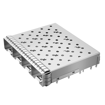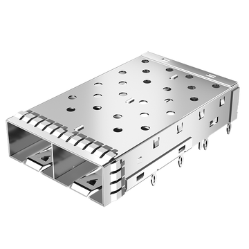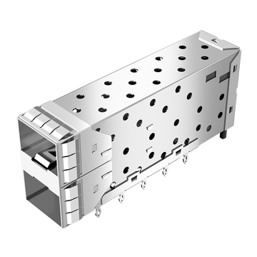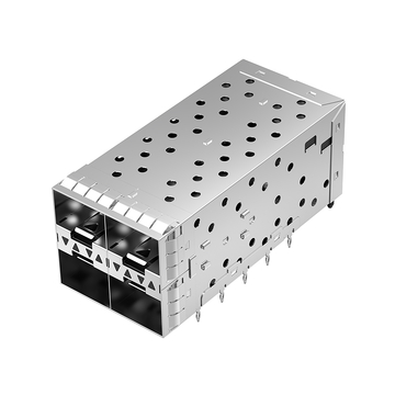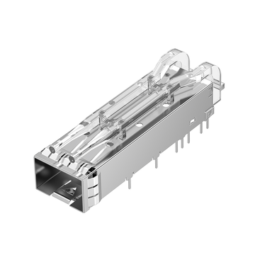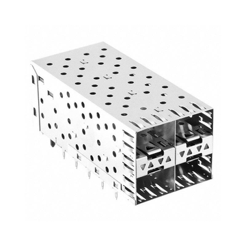
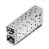
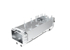
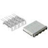

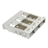

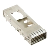


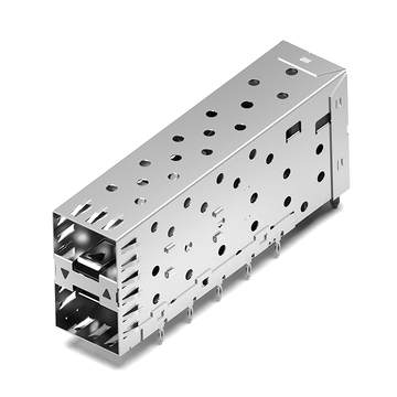



High-density networking equipment requires compact, reliable interfaces that support multiple pluggable transceivers without compromising mechanical stability or electromagnetic compatibility. A 1x4 SFP+ cage addresses this requirement by integrating four transceiver ports into a single ganged assembly, making it suitable for switches, routers, network interface cards, and data center hardware.
The TE Connectivity 2007132-1 is a four-port SFP+ cage assembly featuring through-hole press-fit mounting and internal/external EMI springs. For engineers developing new hardware or evaluating alternative components, understanding its datasheet, mechanical dimensions, PCB footprint, and mounting requirements is essential. LINK-PP offers the LP14BC02000 as a corresponding alternative for 2007132-1 applications.
This guide examines the key technical and practical considerations involved in selecting and integrating this 1x4 SFP+ cage, including:
-
2007132-1 specifications, dimensions, and mechanical construction.
-
PCB footprint, press-fit mounting, and grounding requirements.
-
EMI shielding and high-speed interface design considerations.
-
LINK-PP LP14BC02000 alternative and compatibility evaluation.
-
Component selection, prototype testing, and production validation.
These details help hardware engineers assess cage compatibility, reduce PCB integration risks, and establish a more reliable SFP+ interface design.
What Is the TE Connectivity 2007132-1 SFP+ Cage?
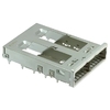
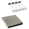
The TE Connectivity 2007132-1 is a ganged 1x4 SFP+ cage assembly designed to accommodate four SFP+ transceivers in a horizontal row. It uses a through-hole press-fit mounting structure and internal/external EMI springs to support mechanical retention and electromagnetic shielding in high-density networking equipment.
Unlike a complete SFP+ interface, the 2007132-1 is the metal cage component rather than the electrical connector itself. It provides the mechanical enclosure and shielding structure around the transceiver ports.
Overview of the 2007132-1 Product
The 2007132-1 belongs to TE Connectivity's high-speed pluggable I/O product family. Its ganged construction combines four SFP+ port openings into one assembly, reducing the need to design and mount four independent cages.
Its main identification characteristics include:
-
Manufacturer: TE Connectivity
-
Part number: 2007132-1
-
Product type: SFP+ cage assembly
-
Form factor: SFP+
-
Port configuration: 1x4
-
Number of ports: 4
-
Cage construction: Ganged
-
PCB termination: Through-hole press-fit
-
EMI containment: Internal and external EMI springs
-
Application: High-speed pluggable I/O interfaces
The cage is designed for SFP+ MSA-compliant transceivers and follows the SFF-8433 specification for improved pluggable form factor SFP+ ganged cages. This makes it relevant to networking hardware that requires multiple adjacent SFP+ interfaces.
How a 1x4 SFP+ Cage Works
A 1x4 SFP+ cage provides four individual transceiver insertion positions within a shared metal housing. Each port accommodates a compatible SFP+ transceiver while the cage maintains the mechanical and shielding structure around the interface.
Its main functions include:
-
Transceiver guidance: Provides a defined insertion path for SFP+ optical modules and direct-attach cable interfaces.
-
Mechanical protection: Surrounds and supports the transceiver interface, helping maintain alignment during insertion and removal.
-
EMI containment: Uses conductive spring contacts to support shielding continuity between the cage and the surrounding chassis.
-
Port organization: Combines four ports into a compact horizontal arrangement.
-
PCB integration: Uses press-fit mounting posts to secure the cage to the circuit board.
A complete SFP+ interface normally involves two distinct components: the metal cage and the electrical connector. The cage surrounds the transceiver, while the separately mounted SMT connector provides the electrical connection between the transceiver and PCB.
This distinction is important when evaluating a replacement. A compatible cage does not automatically replace the electrical connector or eliminate the need to verify the existing PCB connector layout.
Typical Applications of 2007132-1
The 2007132-1 is suitable for equipment that requires four adjacent SFP+ ports within a relatively compact front-panel interface.
Common application scenarios include:
-
Ethernet switches: Four-port SFP+ interfaces for uplink and aggregation connections.
-
Network routers: Multiple high-speed optical or copper transceiver interfaces.
-
Data center equipment: High-density connectivity for server and network infrastructure.
-
Network interface cards (NICs): Multiport network adapters supporting SFP+ connectivity.
-
Telecommunications equipment: Pluggable optical interfaces in enterprise and carrier networking systems.
Its ganged 1x4 structure is particularly useful when PCB space, front-panel port density, and consistent mechanical alignment are important design requirements.
2007132-1 Datasheet: Technical Specifications and Key Features
The 2007132-1 datasheet identifies the component as a four-port SFP+ cage with a maximum specified data rate of 16Gbps, nickel-silver construction, and through-hole press-fit termination. Engineers should evaluate these specifications together rather than treating the port configuration as the only compatibility criterion.
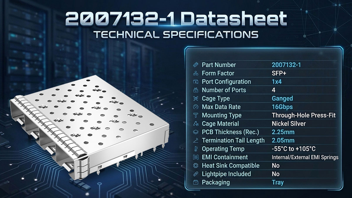
2007132-1 Technical Specifications
The following table summarizes the principal specifications published for TE 2007132-1.
|
Parameter |
Specification |
|---|---|
|
Manufacturer |
TE Connectivity |
|
Part Number |
2007132-1 |
|
Product Type |
SFP+ Cage Assembly |
|
Form Factor |
SFP+ |
|
Cage Type |
Ganged |
|
Port Configuration |
1x4 |
|
Number of Ports |
4 |
|
Maximum Data Rate |
16Gbps |
|
Mounting Method |
Through-Hole Press-Fit |
|
Termination Tail Length |
2.05mm |
|
Cage Material |
Nickel Silver |
|
Recommended PCB Thickness |
2.25mm |
|
Operating Temperature |
-55°C to +105°C |
|
EMI Containment |
Internal/External EMI Springs |
|
Heat Sink Compatible |
No |
|
Included Lightpipe |
No |
|
UL Flammability Rating |
UL 94V-0 |
|
Packaging |
Tray |
Source: TE Connectivity official product information and engineering documentation.
Several specifications deserve particular attention during component selection:
-
16Gbps maximum data rate: This is the cage assembly's published maximum rating. It should not be interpreted as a guarantee of complete system throughput or electrical signal performance.
-
1x4 port configuration: Four SFP+ ports share one ganged metal structure.
-
2.05mm termination tail length: This dimension is relevant to press-fit mounting and PCB hole design.
-
Nickel-silver construction: Provides the conductive metal housing required for the cage structure.
-
Internal/external EMI springs: Support shielding continuity around the transceiver interface.
-
No included lightpipe: Optical status indication must be considered separately if required by the equipment design.
One important distinction is that the cage specifications do not replace the electrical connector's signal-integrity specifications. The electrical connector, PCB routing, and transceiver must also satisfy the system's performance requirements.
Mechanical Dimensions and Port Configuration
The 2007132-1 uses a four-port horizontal arrangement with a repeated port pitch of 14.25mm. Its engineering drawing provides the dimensional references required for PCB positioning, front-panel alignment, and mechanical clearance evaluation.
The main dimensional references include:
|
Mechanical Parameter |
Drawing Dimension |
|---|---|
|
Overall assembly length |
57.25mm |
|
Overall assembly width |
48.70mm |
|
Port-to-port pitch |
14.25mm |
|
Port opening width |
14mm ±0.1mm |
|
Port opening height |
8.95mm ±0.15mm |
|
Termination tail length |
2.05mm |
|
Reference profile height |
9.7mm |
Dimensions are based on the available engineering drawing. Confirm datum orientation and tolerances against the latest controlled drawing before layout release.
The 14.25mm port pitch is particularly important because it determines the repeated spacing of the four transceiver positions. Incorrect interpretation of this dimension can cause misalignment between the cage, PCB connectors, and front-panel openings.
When reviewing the mechanical drawing, engineers should pay attention to:
-
The position of each of the four port openings.
-
The mounting-post pattern and its relationship to the PCB.
-
The cage's overall envelope and front-panel alignment.
-
The insertion and extraction clearance for SFP+ modules.
-
The space required for neighboring components and chassis structures.
These checks help prevent mechanical interference during assembly and operation.
Materials, EMI Springs, and Environmental Characteristics
The 2007132-1 uses a nickel-silver cage housing and internal/external EMI springs. These materials and contact structures support the mechanical strength and shielding functions required by a multiport SFP+ interface.
The main construction considerations are:
-
Nickel-silver housing: Forms the main metal cage structure and provides a conductive enclosure around the transceiver ports.
-
EMI springs: Establish conductive contact with adjacent shielding surfaces to help reduce electromagnetic leakage.
-
Press-fit mounting posts: Secure the assembly to the PCB without relying on conventional soldered cage mounting.
-
UL 94V-0 material classification: Provides a relevant flammability classification for applicable product materials.
-
Temperature rating: The TE specification lists an operating range of -55°C to +105°C.
Environmental specifications should be considered alongside the actual operating conditions of the finished equipment. A cage's rated temperature range does not independently establish the temperature capability of the entire SFP+ interface.
For alternative selection, engineers should also compare the material and finish specifications, spring geometry, and mounting details instead of relying only on the product's external appearance.
2007132-1 PCB Footprint, Mounting, and Mechanical Design Considerations
The 2007132-1 requires a PCB layout that matches its through-hole press-fit mounting structure, hole pattern, and mechanical clearance requirements. PCB thickness, plated-hole dimensions, and mounting-post positioning must be verified before fabrication because an incorrect footprint can cause installation problems or compromise mechanical retention.
Understanding the 2007132-1 Press-Fit Mounting Structure
The 2007132-1 uses through-hole press-fit termination to attach the metal cage to the PCB. Its mounting posts are inserted into prepared PCB holes, creating a mechanically retained connection without requiring conventional soldering of the cage posts.
The main design considerations include:
-
Mounting post geometry: Verify the number, location, and dimensions of the press-fit posts.
-
Termination tail length: The specified tail length is 2.05mm and should be considered when evaluating PCB thickness and mounting geometry.
-
Hole diameter: Follow the recommended drill-hole dimensions in TE application specification 114-13120.
-
Hole plating: Confirm the required plating thickness and finished hole dimensions.
-
Installation process: Use an appropriate press-fit installation method and avoid excessive force that could deform the cage or damage the PCB.
Press-fit mounting provides a practical mechanical attachment method for high-density SFP+ cage assemblies. However, the PCB hole dimensions and manufacturing tolerances must follow the manufacturer's requirements.
PCB Thickness and Footprint Compatibility
PCB thickness is a critical factor in 2007132-1 integration because the cage supports both single-sided and double-sided mounting configurations.
The TE engineering drawing specifies the following minimum PCB thickness requirements:
|
PCB Mounting Configuration |
Minimum PCB Thickness |
|---|---|
|
Single-sided mounting |
1.50mm |
|
Double-sided mounting |
2.25mm |
|
TE recommended PCB thickness |
2.25mm |
These values should not be treated as interchangeable design recommendations. The minimum thickness depends on the mounting configuration, and certain mating transceivers may require additional PCB thickness.
Before finalizing the PCB footprint, engineers should:
-
Check the minimum and recommended board thickness.
-
Verify the press-fit hole diameter and plating requirements.
-
Review the mounting-post positions against the engineering drawing.
-
Confirm the available PCB area around the cage.
-
Evaluate whether the selected configuration supports belly-to-belly installation.
TE application specification 114-13120 is an important reference for hole dimensions and press-fit installation requirements. The product drawing should remain the primary source for mechanical layout decisions.
Mechanical Clearance and Layout Planning
Mechanical clearance must be considered across the entire four-port assembly, not just around an individual SFP+ opening. The cage, transceivers, PCB components, and front-panel structure must fit together without interference.
A practical clearance review should cover:
-
Front-panel openings: Align all four SFP+ ports with their corresponding chassis cutouts.
-
Transceiver accessibility: Leave sufficient space for module insertion, extraction, and latch operation.
-
PCB edge clearance: Check the cage's position relative to the board edge.
-
Adjacent components: Avoid interference with capacitors, heat sinks, connectors, and other nearby components.
-
Chassis clearance: Verify that the cage and EMI springs contact the intended shielding surfaces without mechanical obstruction.
-
Assembly access: Consider the installation sequence and available tooling space.
A 3D mechanical review is particularly useful for multiport cage designs because interference may not be obvious from a two-dimensional PCB footprint.
Belly-to-Belly and Single-Sided PCB Integration
The 2007132-1 supports design considerations associated with belly-to-belly SFP+ cage arrangements. This configuration places compatible cage assemblies on opposite sides of a PCB to increase interface density within a limited board area.
The two mounting approaches have different layout requirements:
Single-sided mounting
-
The cage is installed on one side of the PCB.
-
The minimum PCB thickness specified in the drawing is 1.50mm.
-
The opposite board surface can be used for other components, subject to clearance requirements.
-
Mechanical support and front-panel alignment must still be verified.
Double-sided mounting
-
Compatible cage assemblies are arranged on opposite sides of the PCB.
-
The specified minimum PCB thickness is 2.25mm.
-
Component interference and transceiver insertion clearance require additional attention.
-
The board stack-up and mounting arrangement must be checked together.
The choice between these configurations depends on equipment dimensions, port-density targets, thermal conditions, and assembly requirements. A denser layout is only practical when mechanical clearance and service accessibility remain adequate.
2007132-1 EMI Shielding and Signal Integrity Design Best Practices
The 2007132-1 incorporates internal and external EMI springs to support electromagnetic shielding around its four SFP+ ports. However, effective EMI performance depends on the complete interface design, including cage grounding, PCB layout, chassis contact, and the electrical connector.
Understanding Internal and External EMI Springs
EMI springs are conductive contact structures designed to maintain electrical continuity between the cage and surrounding shielding surfaces. In a four-port SFP+ assembly, these contacts help reduce electromagnetic leakage through the port openings.
The two spring arrangements serve related but distinct mechanical contact functions:
-
Internal EMI springs: Provide conductive contact within the cage structure around the transceiver interface.
-
External EMI springs: Support conductive contact between the outside of the cage and the surrounding chassis or shielding structure.
-
Spring contact pressure: Helps maintain electrical continuity when compatible transceivers are inserted.
-
Conductive shielding paths: Support the overall EMI containment strategy of the equipment.
The presence of EMI springs is an important cage feature, but it does not independently guarantee compliance with a system's EMC requirements. The chassis interface, grounding design, and final equipment configuration must also be validated.
PCB Grounding and EMI Contact Design
Proper grounding is essential for maintaining effective EMI containment in a 1x4 SFP+ cage design. The PCB grounding structure should work with the cage's conductive housing and the equipment's chassis-ground arrangement.
Engineers should consider the following practices:
-
Provide appropriate chassis-ground pads around the cage mounting area.
-
Follow the recommended grounding locations in the TE engineering drawing.
-
Use suitable grounding vias to connect the relevant PCB ground structures.
-
Maintain the intended conductive contact between the cage and chassis.
-
Avoid solder mask or insulating materials in designated conductive contact areas.
-
Verify that EMI springs are not obstructed or mechanically deformed during assembly.
The TE drawing specifically identifies PCB pads and vias for chassis grounding. These details should be considered during footprint development rather than added as an afterthought.
A grounding design that looks correct in the PCB layout may still perform poorly if the installed cage does not maintain consistent chassis contact. Prototype inspection and system-level EMI testing are therefore important.
High-Speed Signal Integrity Considerations
Although the 2007132-1 is associated with a maximum data rate of 16Gbps, the cage itself is not the component responsible for electrical signal transmission. Signal integrity depends primarily on the electrical connector, PCB interconnect, transceiver, and complete channel design.
The following design elements deserve attention:
-
Controlled impedance: Maintain the required differential impedance in high-speed PCB traces.
-
Connector placement: Position the SFP+ electrical connector according to its recommended PCB footprint.
-
Differential pair routing: Minimize unnecessary routing discontinuities and maintain consistent pair geometry.
-
Crosstalk control: Provide appropriate spacing between adjacent high-speed signal paths.
-
Ground reference: Maintain a suitable reference plane and grounding structure.
-
Channel validation: Evaluate insertion loss, return loss, and other relevant signal-integrity parameters.
The four-port arrangement introduces additional routing and crosstalk considerations because multiple high-speed interfaces occupy a relatively compact area.
For this reason, selecting a suitable SFP+ cage is only one part of the design process. The electrical connector and PCB routing must independently satisfy the intended application requirements.
Common EMI and Integration Problems
EMI problems in SFP+ interfaces often result from poor mechanical contact, incomplete grounding, or incorrect installation rather than the cage's port configuration alone.
Common issues include:
|
Problem |
Possible Cause |
Recommended Check |
|---|---|---|
|
EMI leakage around ports |
Inconsistent spring contact |
Inspect EMI spring contact |
|
Poor chassis grounding |
Incorrect grounding pads or vias |
Review PCB grounding layout |
|
Cage misalignment |
Incorrect mounting-hole pattern |
Compare footprint with drawing |
|
Mechanical gaps |
Incorrect front-panel dimensions |
Check chassis alignment |
|
Damaged press-fit posts |
Incorrect installation force |
Inspect mounting condition |
|
Excessive crosstalk |
PCB routing or grounding issues |
Perform signal-integrity analysis |
These issues should be investigated systematically. A mechanical fit check, grounding inspection, and EMC test can help identify whether the problem originates from the cage, PCB, or chassis design.
LINK-PP LP14BC02000: A Compatible Alternative to TE 2007132-1
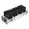
LINK-PP LP14BC02000 is our corresponding 1x4 SFP+ cage alternative for TE Connectivity 2007132-1 applications. It features a ganged four-port configuration, through-hole press-fit mounting, and EMI spring shielding, providing an alternative component option for engineers evaluating SFP+ cage designs.

Overview of LINK-PP LP14BC02000
At LINK-PP, we provide fiber optic cages and connectivity components for networking equipment manufacturers and hardware design projects. LP14BC02000 is part of our 1x4 SFP+ cage product range and is listed as compatible with TE 2007132-1.
Its main product characteristics include:
-
Part number: LP14BC02000
-
Product category: Fiber optic cage assembly
-
Form factor: SFP+
-
Port configuration: 1x4
-
Number of ports: 4
-
Mounting method: Through-hole press-fit
-
EMI containment: Internal/external EMI springs
-
Included lightpipe: No
-
Compatible reference: TE 2007132-1
View LINK-PP LP14BC02000 product details
The model is intended for applications requiring a four-port ganged SFP+ cage. Its corresponding part-number listing makes it a practical starting point for engineers evaluating an alternative to the TE reference model.
TE 2007132-1 vs. LINK-PP LP14BC02000
TE 2007132-1 and LINK-PP LP14BC02000 share the same primary application category and four-port SFP+ cage configuration. However, engineers should compare detailed drawings and specifications before treating the two components as mechanically interchangeable.
The following table summarizes their published product information.
|
Parameter |
TE 2007132-1 |
LINK-PP LP14BC02000 |
|---|---|---|
|
Manufacturer |
TE Connectivity |
LINK-PP |
|
Part Number |
2007132-1 |
LP14BC02000 |
|
Product Type |
SFP+ Cage Assembly |
SFP+ Cage Assembly |
|
Port Configuration |
1x4 |
1x4 |
|
Number of Ports |
4 |
4 |
|
Cage Structure |
Ganged |
Ganged |
|
Mounting Method |
Through-Hole Press-Fit |
Through-Hole Press-Fit |
|
EMI Containment |
Internal/External EMI Springs |
Internal/External EMI Springs |
|
Included Lightpipe |
No |
No |
|
Maximum Data Rate |
16Gbps |
16Gbps (LINK-PP compatibility listing) |
|
Operating Temperature |
-55°C to +105°C |
Confirm against current controlled product documentation |
One specification deserves special attention: LINK-PP's product information is not fully consistent across its published pages. The compatibility listing reports -55°C to +105°C and 16Gbps, while another LP14BC02000 product detail listing reports -40°C to +85°C. Engineers should therefore confirm the applicable product revision and controlled drawing with LINK-PP before approving temperature-critical applications.
The same principle applies to detailed dimensions, press-fit tolerances, and EMI spring geometry. Matching the port configuration and mounting method establishes a useful compatibility reference, but it does not replace a drawing-to-drawing engineering review.
Why Consider LINK-PP SFP+ Cage Solutions?
LINK-PP SFP+ cages provide additional component options for networking hardware manufacturers seeking flexibility in mechanical design and component sourcing. Our product range covers multiple cage configurations, allowing engineers to evaluate different port arrangements and mounting requirements within their equipment platforms.
Key advantages include:
-
Alternative component options: LP14BC02000 provides a corresponding model for TE 2007132-1 applications.
-
Multiple port configurations: Our fiber optic cage range includes different SFP and SFP+ port arrangements.
-
Design flexibility: Different cage structures and mounting options support varied PCB and chassis layouts.
-
Application coverage: Suitable product categories cover switches, routers, network adapters, and other networking equipment.
-
Sourcing flexibility: An additional component source can help manufacturers manage supply-chain requirements.
-
Technical assistance: Our team can help with model identification, product documentation, and compatibility evaluation.
Beyond LP14BC02000, engineers can explore other configurations in our LINK-PP 1x4 SFP+ Cage product category. Selecting a cage based on the actual PCB and chassis requirements is more reliable than choosing a component solely by its port count.
When Is LP14BC02000 Suitable for a 2007132-1 Alternative Design?
LP14BC02000 is worth evaluating when an existing or new hardware design requires a four-port ganged SFP+ cage corresponding to TE 2007132-1.
Typical evaluation scenarios include:
-
Replacing a TE 2007132-1 reference component in an existing design.
-
Developing a new four-port SFP+ interface.
-
Reviewing alternative component sources for ongoing production.
-
Standardizing cage configurations across multiple networking platforms.
-
Evaluating component availability and long-term sourcing flexibility.
Before approving LP14BC02000 as a replacement, engineers should verify:
-
Overall cage dimensions and mounting-post positions.
-
Port opening dimensions and 14.25mm reference port spacing.
-
Press-fit tail geometry and PCB hole requirements.
-
Single-sided or double-sided PCB mounting compatibility.
-
Internal and external EMI spring configurations.
-
Chassis contact and grounding arrangements.
-
Transceiver insertion and extraction clearance.
-
Operating temperature and material specifications.
This validation process is particularly important for existing PCB designs. Even a small difference in mounting-post position or cage geometry can require a footprint or mechanical adjustment.
How to Select and Validate a 2007132-1 Alternative for PCB Design
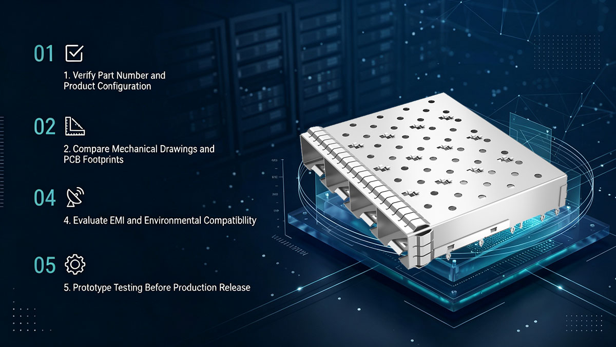
Selecting a 2007132-1 alternative requires more than confirming that both components have four SFP+ ports. Engineers should evaluate product configuration, mechanical dimensions, press-fit compatibility, EMI contact, and environmental specifications before approving a replacement.
Verify Part Number and Product Configuration
The first step is to confirm that the alternative belongs to the correct product category and supports the intended SFP+ port arrangement.
A product-selection review should include:
-
Confirm the component is an SFP+ cage rather than an electrical connector.
-
Verify the 1x4 ganged configuration.
-
Confirm that the assembly accommodates four SFP+ transceivers.
-
Check whether the product includes a lightpipe or heat sink.
-
Verify the mounting method and orientation.
-
Confirm the applicable product revision and documentation.
For LP14BC02000, the published product listing identifies it as a four-port ganged SFP+ cage with through-hole press-fit mounting and EMI springs.
Part-number confirmation should always be followed by a review of the actual engineering drawing.
Compare Mechanical Drawings and PCB Footprints
Mechanical drawing comparison is the most important step when determining whether an alternative cage can fit an existing PCB design.
Engineers should compare:
-
Overall length, width, and height.
-
Port opening dimensions.
-
Port-to-port spacing.
-
Mounting-post positions.
-
Press-fit tail length.
-
PCB hole diameter and plating requirements.
-
Board thickness and mounting configuration.
-
Front-panel and chassis alignment.
A 3D CAD comparison can help identify potential interference before hardware prototypes are produced.
For an existing TE 2007132-1 design, the original drawing should be used as the reference. The LINK-PP LP14BC02000 drawing should then be checked against the same mechanical datums and mounting positions.
If any dimensions differ, determine whether the difference can be accommodated without affecting transceiver alignment, chassis contact, or mechanical retention.
Evaluate EMI and Environmental Compatibility
EMI and environmental specifications must be checked independently of mechanical compatibility. Two cages can share the same 1x4 port arrangement while having different spring geometry, material properties, or temperature ratings.
Important verification items include:
-
Internal and external EMI spring arrangements.
-
Cage-to-chassis conductive contact.
-
Grounding pad and via requirements.
-
Cage housing material and surface finish.
-
Operating temperature range.
-
Applicable material and environmental compliance documentation.
For LP14BC02000, confirm the operating temperature against the latest controlled product documentation because published product listings show different temperature ranges.
This is especially important for telecommunications equipment and industrial networking platforms where operating temperatures may exceed those of conventional office networking hardware.
Prototype Testing Before Production Release
Prototype testing provides the final engineering evidence needed to approve an alternative SFP+ cage. A component that matches the drawing on paper should still be tested in the actual PCB and chassis assembly.
A practical validation process includes:
-
Mechanical fit test: Install the cage on the target PCB and check its alignment.
-
Press-fit inspection: Verify mounting-post insertion, retention, and PCB condition.
-
Transceiver compatibility test: Insert and remove representative SFP+ modules.
-
EMI contact inspection: Check spring contact with the cage and chassis.
-
Front-panel alignment: Confirm that all four ports align with the equipment enclosure.
-
Electrical interface testing: Verify the separately mounted SFP+ connector and PCB channel.
-
Environmental validation: Confirm that the assembly meets the required operating conditions.
-
EMC testing: Evaluate the complete equipment against applicable emissions and immunity requirements.
Testing should use representative production materials and assembly methods wherever possible. This helps identify problems that may not appear in an isolated component inspection.
Once the alternative passes the required mechanical, electrical, and environmental checks, the engineering team can document the approved configuration for production use.
FAQs About 2007132-1
The following answers address common questions about the TE 2007132-1 datasheet, its mechanical requirements, and the LINK-PP alternative.
Q1: What is the TE Connectivity 2007132-1?
TE 2007132-1 is a ganged 1x4 SFP+ cage assembly designed to accommodate four SFP+ transceivers. It uses through-hole press-fit mounting and internal/external EMI springs.
Q2: What is the maximum data rate of 2007132-1?
The specified maximum data rate is 16Gbps. This rating describes the cage product specification and should not be interpreted as a guarantee of complete system-level signal performance.
Q3: Does 2007132-1 include SFP+ electrical connectors?
No. The 2007132-1 is a metal cage assembly. The corresponding SFP+ electrical connectors are separate components mounted on the PCB.
Q4: What is the recommended PCB thickness for 2007132-1?
2.25mm as the recommended PCB thickness. Its engineering drawing also specifies minimum thicknesses of 1.50mm for single-sided mounting and 2.25mm for double-sided mounting.
Q6: Can LP14BC02000 directly replace 2007132-1 without PCB changes?
Yes, but final interchangeability should be confirmed by comparing mechanical drawings, press-fit dimensions, PCB thickness, EMI contacts, and chassis clearance.
Q7: What should engineers check before selecting a 1x4 SFP+ cage?
The most important considerations are port configuration, cage dimensions, mounting-hole patterns, PCB thickness, EMI shielding, grounding, and transceiver accessibility. Environmental ratings should also match the intended equipment application.
Conclusion
The TE Connectivity 2007132-1 datasheet provides an important reference for engineers designing four-port SFP+ interfaces. Its ganged 1x4 configuration, through-hole press-fit mounting, nickel-silver housing, and internal/external EMI springs make it suitable for high-density networking equipment.
When evaluating a 2007132-1 alternative, engineers should focus on more than matching the port configuration. The mechanical footprint, PCB thickness, mounting tolerances, EMI contact structure, and environmental specifications all influence the success of the final design.
Key points to remember:
-
2007132-1 supports four SFP+ ports in a 1x4 ganged arrangement.
-
Its maximum specified data rate is 16Gbps.
-
Press-fit mounting requires careful PCB hole and thickness verification.
-
EMI performance depends on cage grounding and chassis contact.
-
LINK-PP LP14BC02000 provides a corresponding alternative for 2007132-1 applications.
-
Mechanical and environmental compatibility should be validated before production release.
At LINK-PP, we offer a range of fiber optic cages and connectivity components to support different networking hardware designs. If your project references TE 2007132-1, our LP14BC02000 provides an additional option for your engineering evaluation.
Visit the LINK-PP Official Store to review LP14BC02000 product details or explore our broader SFP+ cage portfolio. Our team can assist with model confirmation, technical documentation, and quotation requests. We also provides 15-day no-reason returns and exchanges for eligible standard-stock items. For confirmed quality-related issues, LINK-PP covers the return shipping costs.