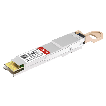
I rack dei vostri data center stanno esaurendo gli slot degli switch mentre la domanda di larghezza di banda continua a crescere vertiginosamente? Con l'espansione di carichi di lavoro moderni come i cluster di intelligenza artificiale e il cloud computing, gli ambienti ad alta densità necessitano urgentemente di soluzioni più intelligenti per scalare senza aggiungere hardware costoso. L'integrazione del ricetrasmettitore ottico QDD-2×100-SR4-S offre una soluzione diretta, massimizzando l'efficienza delle porte e riducendo i costi dell'infrastruttura.
Vi siete mai chiesti come raddoppiare la densità dei collegamenti a 100G senza acquistare ulteriori chassis per switch o aumentare lo spazio rack? La risposta sta nella sostituzione delle tradizionali ottiche a porta singola con architetture di breakout ottico ad alta densità. Suddividendo una singola porta ad alta capacità in due canali indipendenti, gli architetti di rete possono ottimizzare il throughput, migliorare il flusso d'aria e ridurre il consumo energetico complessivo.
✳️ Cos'è il ricetrasmettitore QDD-2×100-SR4-S e come funziona?
Le moderne reti dei data center richiedono interconnessioni ad altissima densità per gestire volumi di traffico in costante aumento. Il transceiver ottico QDD-2×100-SR4-S risponde a questa esigenza consolidando due interfacce ottiche 100G indipendenti in un singolo slot fisico dello switch, raddoppiando di fatto la densità delle porte. Un'analisi più approfondita del suo funzionamento interno rivela come questi moduli ad alta densità massimizzino l'efficienza delle porte, mantenendo al contempo la compatibilità con il cablaggio in fibra MPO-12 esistente tramite semplici cavi breakout.
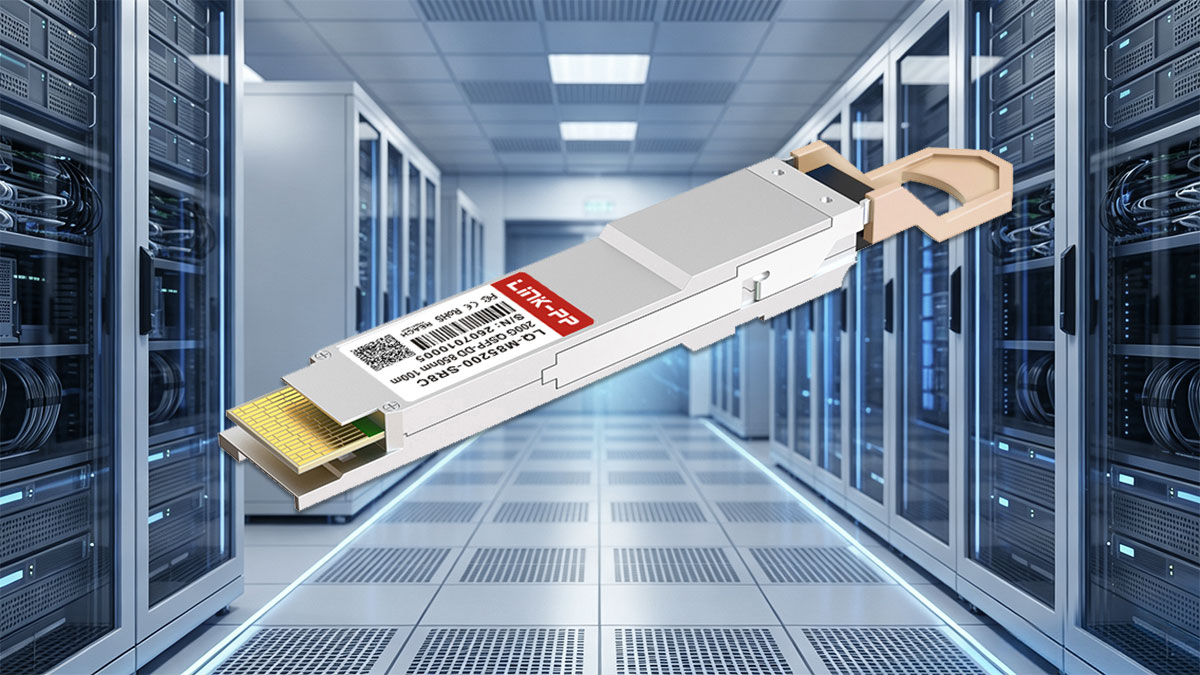
Definizione di base e come due collegamenti da 100G si integrano in una singola porta QSFP-DD
Il QDD-2×100-SR4-S è un modulo ottico QSFP-DD (Quad Small Form-Factor Pluggable Double Density) progettato per offrire una velocità di trasmissione totale di 200G tramite due canali NRZ da 100G completamente indipendenti. Sfruttando l'interfaccia elettrica a 8 corsie del formato QSFP-DD, il modulo assegna 4 corsie elettriche a 25 Gbps a ciascun canale da 100G, raddoppiando di fatto la densità delle porte rispetto ai formati tradizionali.
All'interno del modulo, i motori ottici integrati elaborano due flussi ottici paralleli SR4 da 100G in parallelo. L'hardware dello switch riconosce questi flussi come due interfacce logiche indipendenti, consentendo a un singolo slot fisico dello switch di gestire due collegamenti da 100G tramite ottica parallela diretta, con circuiti interni dedicati esclusivamente alla risincronizzazione del segnale.
Specifiche tecniche principali: tipologie di fibra, limiti di distanza e connettori
L'implementazione del modulo QDD-2×100-SR4-S richiede la rigorosa osservanza dei parametri del livello fisico per garantire un'integrità del segnale ottimale su tratti ottici multimodali ad alta densità.
Di seguito vengono illustrate le principali specifiche tecniche che regolano il funzionamento del livello fisico:
- Fattore di forma: QSFP-DD standard con interfaccia elettrica a 8 corsie.
- Lunghezza d'onda: 850 nm. Trasmettitori VCSEL su fibra multimodale parallela.
- Connettore ottico: connettore MPO-24 integrato nella placca frontale.
- Distanza di trasmissione: fino a 70 m su fibra multimodale OM3; fino a 100 m su fibra multimodale OM4.
- Velocità di trasmissione dati: 200G totali (configurata come 2×100G NRZ a 103.125 Gbps per canale).
- Consumo energetico: design ottimizzato per il risparmio energetico, con un consumo inferiore a 4.5 W.
Comprensione del concetto di breakout ottico da 200G a 2×100G
L'architettura di breakout ottico separa i percorsi dati interni di un ricetrasmettitore multicanale in connessioni di rete indipendenti. Il ricetrasmettitore QDD-2×100-SR4-S opera su un design di breakout 2×100G-SR4, utilizzando un'interfaccia MPO a 24 fibre in cui 16 fibre attive sono suddivise in due set discreti da 8 fibre (4 Tx e 4 Rx per collegamento 100G).
Collegando un cavo di cablaggio da MPO-24 a 2×MPO-12 direttamente al pannello frontale del modulo, i tecnici possono instradare ciascun canale a 8 fibre da 100G verso switch, pannelli di permutazione o nodi server separati senza alcuno sforzo. Questo metodo di breakout fisico preserva la chiarezza del segnale su brevi distanze senza aggiungere latenza o degrado del segnale ottico.
Come si confronta con i moduli QSFP28 SR4 nativi standard da 100G
Il confronto tra il modulo QDD-2×100-SR4-S e i moduli SR4 QSFP28 nativi da 100G di vecchia generazione evidenzia chiare differenze in termini di densità, meccanica del cablaggio ed efficienza energetica per canale.
Un confronto tecnico affiancato illustra le differenze tra questi due modelli di ricetrasmettitore negli scenari di implementazione aziendale:
| Parametro di specifica | Modulo QDD-2×100-SR4-S | Modulo QSFP100 SR28 da 4G |
| Fattore di forma | QSFP-DD | QSFP28 |
| Flusso totale del modulo | 200G (2 canali da 100G) | 100G (Canale singolo) |
| Interfaccia elettrica | 8 corsie (25 Gbps NRZ per corsia) | 4 corsie (25 Gbps NRZ per corsia) |
| Tipo di connettore ottico | MPO-24 singolo | MPO-12 singolo |
| Densità teorica delle porte | Fino a 64 collegamenti da 100G (se tutte le porte supportano la modalità breakout) | 32 collegamenti da 100G (nativi, senza breakout) |
| Assorbimento massimo | <4.5W | <2.5W |
| Architettura di cablaggio | Cavo breakout da MPO-24 a 2×MPO-12 | Cavo singolo punto-punto MPO-12 |
Mentre i moduli QSFP28 100G-SR4 standard occupano una porta dello switch per una singola connessione a 100G, il QDD-2×100-SR4-S può raddoppiare il numero di collegamenti a 100G per slot fisico, a condizione che l'hardware dello switch supporti la funzionalità di breakout. Il modesto risparmio energetico (circa il 10% per collegamento duale rispetto a due moduli QSFP28 individuali) riduce i costi operativi e il carico termico, ma il vantaggio principale rimane l'ottimizzazione della densità delle porte piuttosto che un salto di qualità nell'efficienza energetica.
✳️ Perché utilizzare QDD-2×100-SR4-S per reti di data center ad alta densità
La rapida espansione dei servizi cloud e delle applicazioni ad alta intensità di banda spinge i moderni data center a sfruttare al massimo ogni centimetro quadrato di spazio rack. L'implementazione di ricetrasmettitori ottici ad alta densità risolve i colli di bottiglia fisici critici, consentendo una maggiore larghezza di banda attraverso l'infrastruttura di switch esistente. Sfruttando le architetture breakout 2×100G, gli operatori di rete possono ottenere un throughput scalabile ottimizzando al contempo le spese in conto capitale e le prestazioni operative.
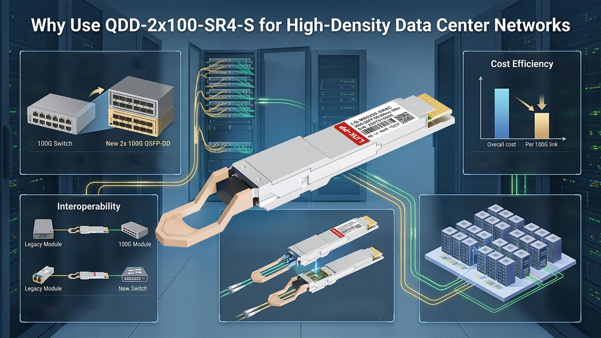
Ottenere una velocità di trasmissione totale di 200G da una singola porta dello switch.
Il motivo principale per l'adozione del modulo ottico QDD-2×100-SR4-S è la sua capacità di estrarre una larghezza di banda aggregata totale di 200G da una singola interfaccia switch QSFP-DD. Le configurazioni tradizionali richiedono due porte QSFP28 separate per ottenere una velocità di trasmissione equivalente, esaurendo rapidamente lo spazio disponibile sugli slot del pannello frontale degli switch ad alta densità.
Dividendo l'interfaccia host elettrica a 8 corsie da 25 Gbps in due collegamenti logici NRZ indipendenti da 100 Gbps, una singola porta funziona come due canali di rete distinti. Questa configurazione raddoppia la densità effettiva delle porte dello switch, consentendo agli architetti di rete di scalare la larghezza di banda totale della struttura senza espandere l'ingombro fisico degli switch.
Rinvio dell'espansione dello switch tramite una maggiore densità di porte
Il QDD-2×100-SR4-S non riduce i costi di acquisto per singolo ricetrasmettitore, anzi, ha un prezzo superiore a quello di due moduli QSFP28 SR4 autonomi. Il suo reale vantaggio in termini di investimento iniziale deriva dal consolidamento delle porte. Offrendo due collegamenti a 100G per slot fisico, consente ai data center di supportare un maggior numero di connessioni a 100G all'interno di uno chassis switch esistente.
Questa maggiore densità può posticipare o evitare l'acquisto di ulteriori schede di linea switch o di interi chassis con l'aumentare del traffico, offrendo un vantaggio strategico in termini di investimenti (CapEx) quando si scala la capacità della rete, a condizione che la piattaforma host supporti il funzionamento breakout.
Riduzione del consumo energetico per canale 100G nei rack
L'efficienza energetica rimane una priorità operativa fondamentale nelle implementazioni rack ad alta densità, dove la dissipazione termica limita le prestazioni dell'hardware. Sebbene il consolidamento dei moduli ottici non elimini completamente il consumo energetico, l'utilizzo di un singolo modulo a doppio canale consente un risparmio energetico misurabile rispetto al funzionamento di più ricetrasmettitori individuali.
Il funzionamento di un modulo QDD-2×100-SR4-S consuma meno di 4.5 W, ovvero meno di 2.25 W per collegamento 100G attivo. Rispetto all'utilizzo di due moduli QSFP28 100G standard, che assorbono fino a 2.5 W ciascuno, questa configurazione consente una riduzione incrementale del consumo energetico di circa il 10% per canale 100G, contribuendo a diminuire leggermente la dissipazione termica complessiva del rack.
Ridurre l'ingombro dei cavi e migliorare il flusso d'aria dietro gli interruttori
I pannelli di permutazione ad alta densità spesso soffrono di un grave ingorgo di cavi, che limita la ventilazione termica dei corridoi caldi e freddi dietro i rack dei server. La gestione di fitti fasci di cavi patch in fibra ottica punto-punto complica la manutenzione ordinaria e aumenta il rischio di piegature accidentali delle fibre.
L'utilizzo del QDD-2×100-SR4-S con il cablaggio strutturato breakout MPO-24 semplifica notevolmente la disposizione fisica dei cavi. Il consolidamento di due flussi ottici da 100G in un'unica connessione trunk riduce il volume totale dei cavi dietro gli switch, liberando spazio per l'espulsione del flusso d'aria delle ventole e migliorando l'efficienza del raffreddamento nei rack ad alta densità.
✳️ In che modo QDD-2×100-SR4-S migliora le connessioni degli interruttori a spina dorsale?
Le moderne infrastrutture dei data center si basano in larga misura su architetture Leaf-Spine non bloccanti per elaborare enormi volumi di traffico dati est-ovest. L'integrazione di moduli ottici breakout ad alta densità consente agli architetti di rete di scalare la larghezza di banda in uplink e downlink senza aggiungere slot fisici agli switch. L'implementazione del transceiver QDD-2×100-SR4-S ottimizza le interconnessioni di rete raddoppiando la disponibilità di collegamenti fisici per porta e semplificando la connettività tra gli switch.
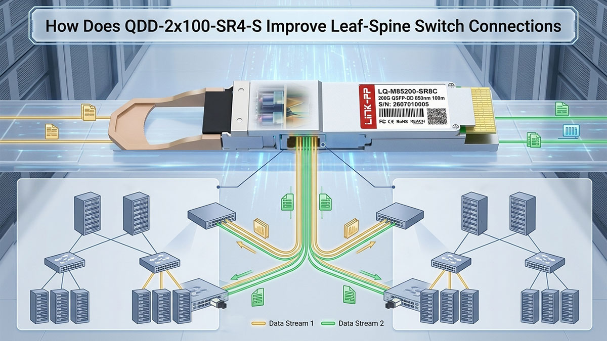
Raddoppiare la capacità tra gli switch senza aggiungere slot per gli switch
Il collegamento degli switch leaf agli switch spine centrali richiede un'aggregazione di uplink ad alta densità per mantenere rapporti di fabric non bloccanti. I moduli QSFP28 standard da 100G occupano rapidamente gli slot chassis disponibili sugli switch spine, costringendo le organizzazioni ad acquistare schede di linea aggiuntive o switch di livello superiore.
L'implementazione del modulo ottico QDD-2×100-SR4-S consente a un singolo slot QSFP-DD su uno switch di dorsale di fornire due collegamenti NRZ 100G indipendenti. Questa funzionalità di breakout raddoppia di fatto la capacità ottica tra switch per porta fisica, consentendo agli ingegneri di rete di espandere la larghezza di banda leaf-to-spine preservando al contempo il prezioso spazio disponibile sugli switch di core.
Eliminazione della congestione delle porte per un traffico server-to-server più veloce.
Le moderne applicazioni cloud e i microservizi dipendono da una rapida comunicazione server-to-server (est-ovest) tra i rack del data center. Quando i collegamenti uplink leaf-to-spine sono sovraccarichi di porte, il buffering dei pacchetti porta a un aumento della latenza e a colli di bottiglia nella velocità di trasmissione.
Sfruttando il modulo ottico QDD-2×100-SR4-S, si espande il numero di uplink logici per porta fisica. Sebbene ciò non aumenti la larghezza di banda bisezionale assoluta della rete (che rimane limitata dall'ASIC dello switch e dal numero totale di porte), migliora significativamente la distribuzione del traffico sulla capacità disponibile.
Tra i principali miglioramenti prestazionali conseguiti lungo le vie di comunicazione est-ovest si annoverano:
- Distribuzione dell'hash ECMP migliorata: un maggior numero di collegamenti logici riduce la probabilità di collisioni di flusso, garantendo un migliore utilizzo di tutti i collegamenti uplink disponibili.
- Riduzione della congestione da micro-burst: la distribuzione del traffico su due canali da 100G riduce l'occupazione istantanea del buffer per interfaccia logica durante i picchi di traffico.
- Latenza e jitter ridotti al minimo: una minore profondità della coda per collegamento garantisce ritardi di transito uniformi per le chiamate ai microservizi tra nodi distribuiti.
- Throughput non bloccante: mantiene le prestazioni alla velocità di linea tra i rack dei server senza perdita di pacchetti, a condizione che la rete complessiva non sia sovraccarica.
Collegamento pulito di una porta dello switch Spine a due switch Leaf
Nelle configurazioni di rete tradizionali, il collegamento di uno switch spine a due switch leaf separati richiede due moduli transceiver dedicati e due porte switch. Questa configurazione fisica esaurisce rapidamente le porte del pannello frontale degli switch spine quando si interconnette un gran numero di nodi leaf.
Con il transceiver QDD-2×100-SR4-S, una singola porta QSFP-DD su uno switch spine si collega in modo ordinato a due switch leaf distinti tramite un cavo breakout da MPO-24 a 2×MPO-12. Ciascun canale ottico indipendente da 100G si connette a uno switch leaf separato, consentendo un rapporto di sdoppiamento 1:2 che semplifica il cablaggio strutturato e ottimizza l'allocazione delle porte nell'intera rete.
Configurazione di connessioni a doppio percorso per prevenire interruzioni di rete
Le infrastrutture di data center ad alta disponibilità richiedono topologie multi-homing resilienti per proteggersi da singoli punti di guasto ottico o hardware. Gli operatori di rete spesso implementano il routing Equal-Cost Multi-Path (ECMP) e i Link Aggregation Group (LAG) sulle connessioni leaf-spine per garantire la continuità operativa.
L'utilizzo del design a doppio canale del modulo QDD-2×100-SR4-S semplifica la creazione di percorsi ridondanti nella rete.
I principali meccanismi architetturali per la tolleranza ai guasti includono:
- Uplink a doppia connessione: collega uno switch leaf a due porte spine indipendenti utilizzando canali ottici separati da 100G.
- Bilanciamento del carico ECMP attivo: distribuisce il traffico est-ovest in modo uniforme su entrambi i collegamenti breakout da 100G per la massima efficienza del percorso.
- Failover rapido del collegamento: garantisce una rapida convergenza in caso di degrado di una delle fibre ottiche, reindirizzando il traffico senza interrompere le sessioni attive.
- Isolamento hardware: tratta ciascun canale 100G come una porta logica indipendente per prevenire la perdita totale del collegamento durante guasti localizzati.
✳️ Perché QDD-2×100-SR4-S è ideale per l'intelligenza artificiale e il calcolo ad alte prestazioni?
I carichi di lavoro di intelligenza artificiale (IA) e di calcolo ad alte prestazioni (HPC) spingono le moderne infrastrutture dei data center ai loro limiti fisici, richiedendo latenza ultra-bassa ed estrema densità di interconnessione. L'elaborazione distribuita su GPU si basa su massicci collegamenti ottici paralleli per impedire che i nodi di calcolo rimangano inattivi in attesa dei dati. L'implementazione del transceiver QDD-2×100-SR4-S consente agli architetti di reti IA di raddoppiare la densità di interconnessione tra le infrastrutture di calcolo e di storage senza compromettere l'integrità del segnale o i limiti di latenza.
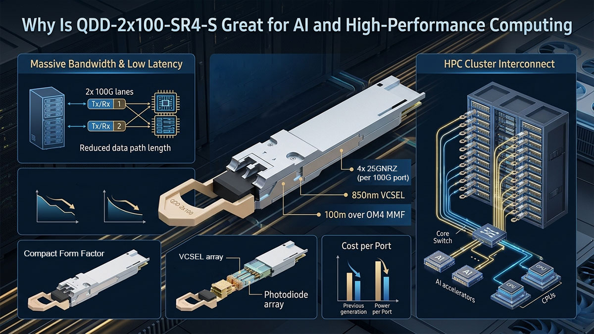
Collegamento diretto dei rack GPU ai nodi di archiviazione a bassa latenza
I cluster di intelligenza artificiale ad alte prestazioni richiedono lo streaming continuo e a bassa latenza di enormi set di dati di addestramento da pool di storage NVMe direttamente alle memorie GPU. Qualsiasi ritardo o instabilità di rete mette fuori uso i costosi acceleratori, aumentando drasticamente i tempi di addestramento dei modelli e i costi operativi.
Il collegamento di array di storage tramite il modulo ottico QDD-2×100-SR4-S crea percorsi diretti e non multiplexati a 100G che bypassano i complessi livelli di traduzione di protocollo. L'utilizzo di ottiche parallele a corto raggio su fibra multimodale OM4 mantiene la latenza del livello ottico a livelli inferiori al microsecondo (tipicamente ~300 ns su brevi tratti), garantendo che i nodi GPU ricevano un flusso costante e ininterrotto di dati di training.
Massimizzazione del numero di porte sugli switch ToR per cluster di intelligenza artificiale
Gli switch Top-of-Rack (ToR) nei cluster di intelligenza artificiale esauriscono rapidamente le porte fisiche disponibili quando si collegano nodi server GPU ad alta densità. Le tradizionali interfacce a 100G occupano troppo velocemente gli slot del pannello frontale, costringendo gli operatori ad aggiungere ulteriori livelli di switch che aumentano la latenza di rete e i costi.
L'implementazione di ottiche breakout 2×100G trasforma l'efficienza degli switch ToR grazie a diversi vantaggi chiave a livello fisico:
- Interfacce logiche raddoppiate per switch: offre 64 interfacce logiche da 100G per 1RU (32 porte fisiche di breakout); il numero effettivo di server dipende dalle schede di rete per nodo e dalla ridondanza.
- Cablaggio semplificato e ottimizzato per i binari: compatibile con le topologie di rete multi-binario tipiche delle moderne architetture dei server GPU.
- Riduzione del numero di hop tra i livelli: elimina i livelli di aggregazione degli switch intermedi per mantenere costante la latenza del cluster.
- Spazio rack ottimizzato: massimizza la densità di calcolo liberando preziosi slot sul pannello frontale per hardware aggiuntivo.
Gestione dei picchi di traffico improvvisi durante l'addestramento di modelli di intelligenza artificiale su larga scala
L'addestramento distribuito di modelli di intelligenza artificiale genera enormi picchi di traffico sincronizzati durante i cicli di scambio del gradiente, come nelle operazioni AllReduce. Se i canali di rete non dispongono di una larghezza di banda parallela sufficiente, questi schemi di comunicazione a raffica causano gravi perdite di pacchetti sulle porte e congestione a micro-raffiche.
Il modulo QDD-2×100-SR4-S attenua i colli di bottiglia causati dai picchi di traffico fornendo due distinte linee logiche a 100G per ogni slot fisico. L'assegnazione di canali logici indipendenti a 100G a diverse linee di elaborazione impedisce la diafonia del traffico, consentendo agli switch di distribuire i micro-picchi improvvisi est-ovest su un maggior numero di collegamenti logici, riducendo la probabilità di saturazione delle singole code.
Riduzione della perdita di dati e dei pacchetti scartati tra i nodi di calcolo
Le suite di protocolli Ethernet senza perdita di dati come RoCEv2 (RDMA su Ethernet convergente) richiedono l'assenza di perdita di pacchetti per evitare cali catastrofici di throughput durante l'esecuzione di carichi di lavoro di intelligenza artificiale. La perdita di pacchetti innesca ritrasmissioni che bloccano le pipeline di esecuzione della GPU, degradando gravemente l'efficienza complessiva del cluster.
L'integrazione del ricetrasmettitore QDD-2×100-SR4-S contribuisce a mantenere operazioni di rete senza perdite attraverso meccanismi ottici e logici chiave:
- Basso tasso di errore di bit: mantiene segnali ottici puliti su brevi tratti multimodali per ridurre al minimo la corruzione dei frame.
- Allocazione buffer dedicata: separa il traffico su porte logiche discrete da 100G, isolando i frame di pausa della coda.
- Mitigazione del blocco PFC: riduce i picchi di flusso prioritario distribuendo i flussi impulsivi su percorsi fisici separati.
- Margini di potenza ottica stabili: garantisce un'uscita del trasmettitore VCSEL costante per prevenire oscillazioni del collegamento sotto carico elevato.
✳️ Guida al cablaggio e all'installazione per i connettori breakout QDD-2×100-SR4-S
L'implementazione di collegamenti ottici ad alta densità richiede un'attenta pianificazione dell'infrastruttura fisica per preservare l'integrità del segnale e mantenere un layout ordinato dei rack. La corretta selezione delle fibre, l'allineamento dei connettori e l'instradamento strutturato dei cavi garantiscono che i collegamenti ad alta velocità funzionino in modo affidabile senza superare i limiti di perdita di inserzione. Seguire le consolidate prassi di cablaggio ottico semplifica l'installazione del transceiver QDD-2×100-SR4-S in ambienti data center aziendali e cloud.
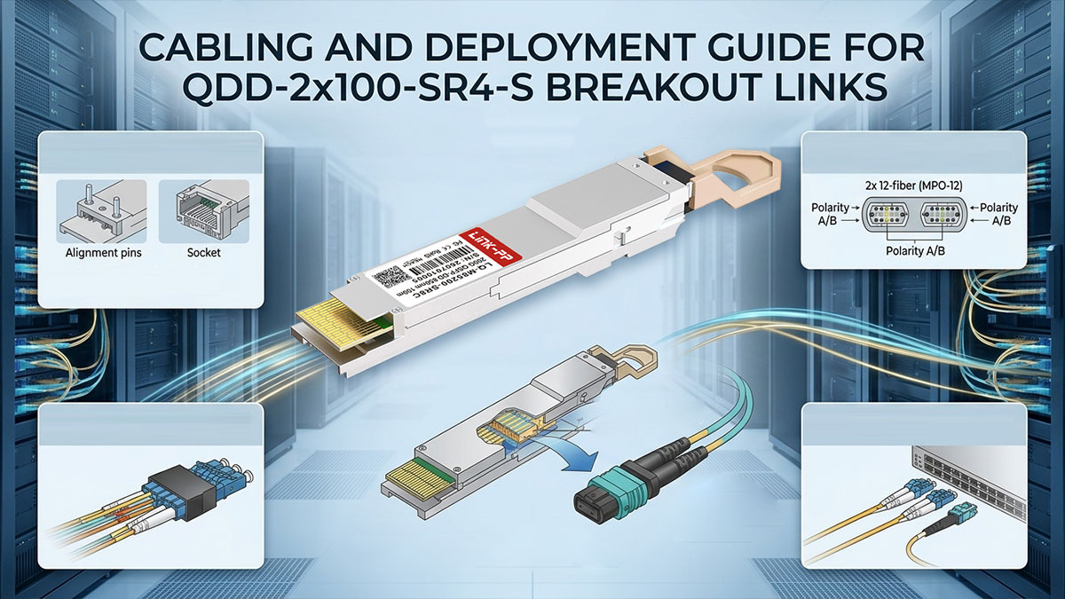
Utilizzo di cavi breakout da MPO-24 a 2×MPO-12 per collegamenti diretti
Il ricetrasmettitore QDD-2×100-SR4-S utilizza un'interfaccia a piastra frontale MPO-24 che suddivide in modo netto la capacità aggregata di 200G in due flussi ottici indipendenti da 100G. Collegando un cavo di derivazione da MPO-24 a 2×MPO-12 direttamente al modulo, una singola porta QSFP-DD si trasforma in due distinti canali a 8 fibre da 100G.
Questa configurazione di breakout fisico consente agli ingegneri di rete di instradare ciascun ramo dell'MPO-12 verso switch di destinazione o pannelli di permutazione separati, senza conversioni ottiche intermedie. Eliminando piastre adattatrici o transcodificatori attivi aggiuntivi, i collegamenti diretti del cablaggio riducono al minimo l'attenuazione ottica, semplificando al contempo le connessioni punto-punto a breve distanza.
Limiti di distanza e ottimizzazione del budget di collegamento su fibra multimodale OM3/OM4
Per ottenere una trasmissione affidabile alla velocità di linea con il modulo ottico QDD-2×100-SR4-S, è fondamentale abbinare le qualità della fibra multimodale ai requisiti specifici di portata. La perdita di inserzione totale deve rimanere rigorosamente entro i limiti del collegamento del ricetrasmettitore per evitare il degrado del tasso di errore di bit su percorsi ottici paralleli.
Le principali soglie di distanza fisica e le considerazioni relative al budget di potenza ottica includono:
- Limite di portata OM3: supporta distanze di trasmissione fino a 70 m.
- Limite di portata OM4: estende la distanza massima di trasmissione fino a 100 m.
- Perdita di collegamento totale massima: mantiene l'attenuazione end-to-end al di sotto di 1.9 dB (secondo IEEE 802.3bm) sia per OM3 che per OM4, inclusi tutti i connettori e le giunzioni.
- Controllo della perdita del connettore: limita ciascun connettore MPO a ≤0.35 dB (secondo TIA-568) per rimanere entro il budget totale di 1.9 dB, consentendo più collegamenti tra pannelli di permutazione, se necessario.
- Larghezza di banda modale: richiede fibra OM3/OM4 di alta qualità con sufficiente larghezza di banda modale effettiva (EMB) per ridurre al minimo la dispersione modale a 850 nm.
Progettazione di cablaggi strutturati tramite pannelli di permutazione e cavi trunk MPO
Le implementazioni su larga scala dei data center si basano su architetture di cablaggio strutturato per organizzare fitti collegamenti in fibra ottica tra le file di switch e gli armadi server. L'integrazione del transceiver QDD-2×100-SR4-S nei pannelli di permutazione strutturati evita l'ingombro dei cavi punto-punto diretti, proteggendo al contempo i connettori ottici sensibili.
I principi essenziali per la progettazione di cablaggi strutturati per collegamenti breakout ad alta densità includono:
- Aggregazione di canaline MPO: instrada i cavi di canalizzazione MPO-24 ad alto numero di fibre attraverso canaline aeree o passaggi sotto il pavimento.
- Pannelli di derivazione a cassetta: Utilizza cassette di transizione da MPO-24 a 2×MPO-12 all'interno di pannelli di permutazione montati su rack per una mappatura delle porte ordinata e una gestione semplificata dei cavi sul telaio di distribuzione.
- Allineamento di polarità di tipo B: garantisce la corretta mappatura della fibra di trasmissione-ricezione su tutti i canali di breakout paralleli.
- Patching flessibile: consente una rapida riconfigurazione dei collegamenti sul pannello di permutazione senza interrompere i moduli QDD-2×100-SR4-S attivi nello chassis dello switch.
Le migliori pratiche per la gestione dei cavi in rack puliti e facili da manutenere.
Mantenere un cablaggio fisico ordinato dietro gli switch ad alta densità previene sollecitazioni meccaniche sui ricetrasmettitori ottici e preserva percorsi di flusso d'aria adeguati. Piegare i cavi in fibra ottica oltre il loro raggio di curvatura minimo introduce una grave perdita di potenza, che degrada i livelli di potenza ottica e provoca oscillazioni del collegamento.
Durante l'installazione dei cavi breakout per il modulo QDD-2×100-SR4-S, i tecnici devono fissare i conduttori del cablaggio utilizzando chiusure a strappo anziché fascette di plastica strette. Un corretto supporto dei cavi verticali nei gestori di rack riduce la tensione sulla piastra frontale del ricetrasmettitore, garantendo un allineamento meccanico stabile e un'affidabilità del collegamento a lungo termine.
✳️ Risoluzione dei problemi comuni di collegamento e segnale del QDD-2×100-SR4-S
Mantenere la stabilità del livello fisico alla velocità di linea su collegamenti breakout ad alta densità richiede una diagnosi sistematica delle interfacce ottiche e logiche. Anche una minima contaminazione della fibra o una configurazione errata del cablaggio possono compromettere i flussi ottici paralleli e causare interruzioni di collegamento impreviste. L'applicazione di procedure diagnostiche strutturate garantisce l'isolamento e la risoluzione rapidi dei guasti del segnale fisico nelle implementazioni QDD-2×100-SR4-S.
Pulizia e ispezione delle interfacce MPO per evitare un'elevata attenuazione ottica
La contaminazione microscopica da polvere e olio sulle superfici terminali dense delle fibre MPO-24 rappresenta la principale causa di un'elevata perdita di inserzione ottica nei collegamenti multimodali paralleli. Poiché un nucleo sporco su una singola fibra può aumentare il BER (Bit Error Rate) sulla corsia corrispondente, potenzialmente innescando errori FEC (Fiber Error Correction) sull'intero canale a 100G, è fondamentale ispezionare tutte le superfici terminali delle fibre con un microscopio per fibre ottiche prima dell'accoppiamento.
I tecnici devono pulire le superfici delle ferrule dei connettori utilizzando appositi pulitori a secco MPO o pulitori a cassetta senza lanugine specificamente progettati per array multifibra. L'adozione di rigorosi protocolli di ispezione prima di inserire i cavi nel ricetrasmettitore QDD-2×100-SR4-S previene graffi fisici permanenti e mantiene l'attenuazione entro il limite di 1.9 dB.
Verifica della potenza di trasmissione e ricezione ottica tramite CLI
Gli strumenti di diagnostica tramite interfaccia a riga di comando (CLI) forniscono visibilità in tempo reale sulle metriche di monitoraggio ottico digitale (DOM) su tutti i canali attivi del modulo. L'esecuzione dei comandi di stato del ricetrasmettitore consente agli ingegneri di rete di verificare se i livelli di potenza ottica in trasmissione (Tx) e in ricezione (Rx) rimangono entro le normali soglie operative.
Un calo improvviso della potenza di ricezione su un canale specifico indica in genere la presenza di connettori MPO sporchi, micro-piegature nel cavo in fibra ottica o danni ai tratti di cavo. Il confronto tra la telemetria CLI in tempo reale e le specifiche di potenza di riferimento garantisce una rapida identificazione dei tratti ottici degradati prima che si verifichi un guasto totale del collegamento.
Risoluzione dei problemi relativi a instabilità di collegamento, tassi di errore di bit (BER) e mappature delle porte di breakout.
Le oscillazioni intermittenti del collegamento e gli elevati tassi di errore di bit (BER) derivano in genere da configurazioni di breakout delle porte non corrispondenti tra il sistema operativo dello switch e il livello fisico. Se l'interfaccia dello switch host non è configurata esplicitamente in modalità breakout 2×100G, l'ASIC dello switch non può mappare le linee elettriche dell'host sui due canali logici del modulo QDD-2×100-SR4-S.
Gli ingegneri devono verificare che la velocità dell'interfaccia, le impostazioni di canalizzazione e i profili di correzione degli errori in avanti (FEC) corrispondano a parametri identici sui nodi remoti connessi. L'allineamento dei comandi di configurazione del software con le mappature fisiche dei breakout elimina gli errori di framing e stabilizza la trasmissione dei dati alla velocità di linea.
Risoluzione dei problemi di incompatibilità di polarità della fibra e degli errori di allineamento del canale
Una mappatura errata della polarità della fibra lungo i collegamenti trunk MPO causa la completa perdita del segnale ottico, disallineando gli array VCSEL del trasmettitore con i fotodiodi del ricevitore. In un collegamento breakout 2×100G, l'utilizzo di una polarità del cavo errata (ad esempio, di tipo A anziché di tipo B) disallinea la mappatura della fibra da trasmettitore a ricevitore: il ricevitore continua a ricevere luce, ma sui canali sbagliati, impedendo il corretto recupero del segnale.
La risoluzione dei problemi di polarità prevede la tracciatura del percorso end-to-end della fibra per garantire il corretto orientamento della chiave attraverso i pannelli di permutazione e gli adattatori a cassetta. La verifica che le corsie in fibra Tx siano mappate direttamente sui corrispondenti canali Rx ripristina l'erogazione di potenza ottica e ristabilisce un allineamento stabile del collegamento per il ricetrasmettitore QDD-2×100-SR4-S.
✳️ Considerazioni finali sull'implementazione di QDD-2×100-SR4-S in architetture breakout ad alta densità
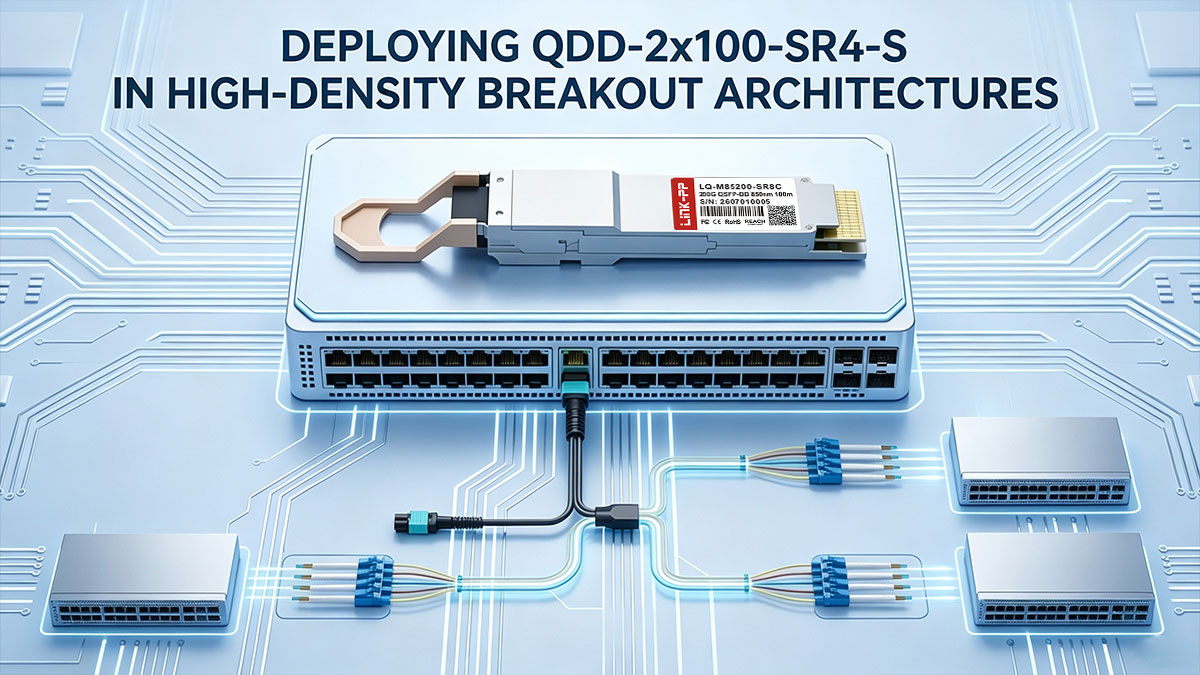
L'implementazione del ricetrasmettitore ottico QDD-2×100-SR4-S rappresenta una strategia estremamente efficace per i moderni data center che mirano a massimizzare la densità delle porte sul pannello frontale senza espandere l'ingombro fisico degli switch. Consolidando due flussi NRZ 100G indipendenti in un singolo slot QSFP-DD, gli architetti di rete possono ottimizzare le interconnessioni Leaf-Spine, accelerare i cluster di calcolo AI e posticipare costosi aggiornamenti degli chassis degli switch. Il successo dell'implementazione dipende in ultima analisi dalla combinazione di un cablaggio breakout MPO-24 preciso, rigorosi protocolli di pulizia delle superfici di contatto e moduli ottici ad alte prestazioni compatibili.
Per le reti aziendali che cercano soluzioni ottiche affidabili ed economiche per implementazioni breakout ad alta densità, i ricetrasmettitori compatibili di terze parti di alta qualità offrono un'alternativa ideale ai moduli OEM. LINK-PP Il modulo ottico LQ-M85200-SR8C 200G QSFP-DD offre la piena compatibilità con le specifiche Cisco QDD-2×100-SR4-S, garantendo prestazioni a velocità di linea e bassa latenza su collegamenti in fibra multimodale OM3/OM4.
Per esplorare i moduli ricetrasmettitori ottici di livello aziendale completamente testati per gli aggiornamenti della tua rete ad alta densità, visita il LINK-PP Negozio ufficiale oggi.