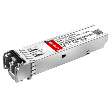
State cercando un modo affidabile per ridurre i costi hardware senza compromettere le prestazioni della vostra rete Meraki? Vi state chiedendo se un ricetrasmettitore compatibile con MA-SFP-1GB-SX di terze parti possa davvero offrire la stessa affidabilità di un modulo originale Meraki? In tal caso, imparare a valutare correttamente queste alternative economiche è fondamentale per mantenere una rete stabile e ad alta velocità.
Ma come reagisce effettivamente uno switch Meraki quando si collega un ricetrasmettitore non OEM? Quali specifiche tecniche è necessario verificare per evitare fastidiosi avvisi nella dashboard e perdita di pacchetti? In questo articolo, analizzeremo a fondo i test ottici essenziali, i benchmark delle prestazioni e la convalida della compatibilità necessari per garantire che le alternative di terze parti MA-SFP-1GB-SX funzionino in modo impeccabile.
🌾 Specifiche chiave da verificare prima di valutare un'alternativa di terze parti al modulo MA-SFP-1GB-SX
L'installazione di un modulo ottico MA-SFP-1GB-SX di terze parti richiede una rigorosa corrispondenza con le specifiche hardware originali per evitare interruzioni di rete. Saltare questi controlli fondamentali può causare guasti immediati al collegamento o perdite di pacchetti, anche minime, nell'infrastruttura in fibra. Un preciso allineamento tecnico garantisce che il ricetrasmettitore alternativo si integri perfettamente con l'ecosistema Meraki esistente.
Verifica dello standard 1000BASE-SX e della lunghezza d'onda di 850 nm
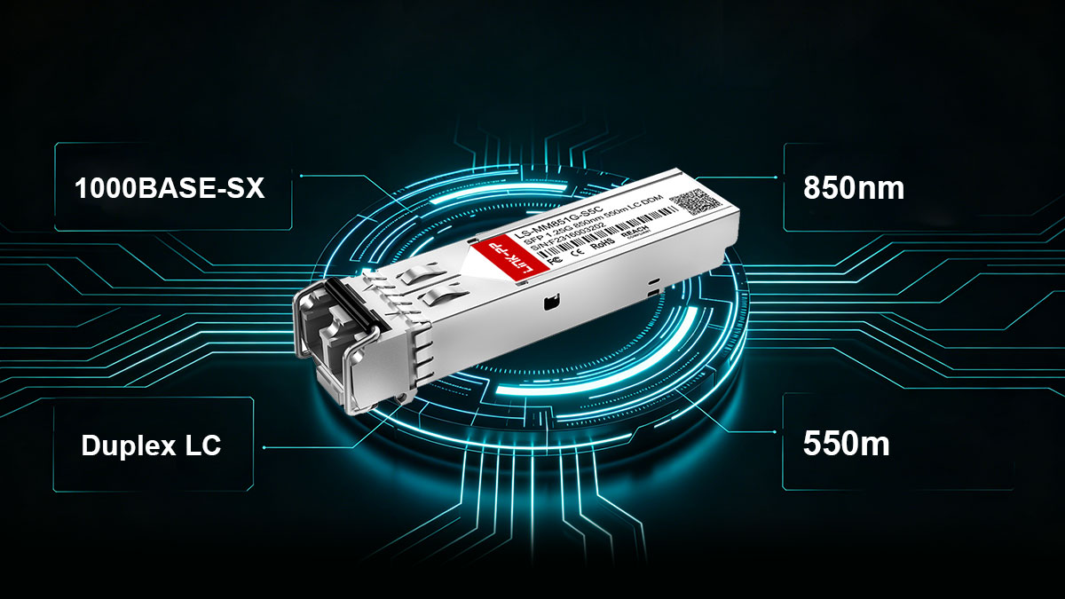
La base per un'implementazione di successo risiede nella conformità alle specifiche del livello fisico standard del settore. Il modulo originale Meraki MA-SFP-1GB-SX opera rigorosamente secondo lo standard 1000BASE-SX, che regola la trasmissione Gigabit Ethernet su fibra ottica a lunghezza d'onda corta. Assicurarsi che la soluzione alternativa di terze parti sia conforme a questo standard garantisce l'interoperabilità di base a livello fisico.
Fondamentalmente, questo standard utilizza una lunghezza d'onda laser di 850 nm per trasmettere i dati attraverso il nucleo di vetro. Se il modulo alternativo utilizza una lunghezza d'onda diversa, i segnali luminosi non saranno compatibili con le apparecchiature ottiche standard a corto raggio. Verificare con precisione questa specifica di 850 nm è la prima linea di difesa contro costosi problemi di incompatibilità dei componenti.
Garantire la compatibilità con le fibre multimodali
La fibra multimodale (MMF) è specificamente progettata per gestire la luce a lunghezza d'onda corta emessa dai ricetrasmettitori 1000BASE-SX. Il modulo MA-SFP-1GB-SX di terze parti deve essere progettato esplicitamente per infrastrutture MMF e non per sistemi a fibra monomodale. L'utilizzo combinato di questi tipi di fibra provoca una grave dispersione della luce, che impedisce completamente la creazione del collegamento ottico.
La maggior parte delle reti moderne utilizza cavi MMF da 50/125 µm per ottimizzare la trasmissione della luce e ridurre al minimo l'attenuazione del segnale. Il modulo alternativo selezionato deve essere compatibile con queste specifiche geometrie del nucleo in vetro per garantire un comportamento prevedibile della rete. Verificare attentamente questa compatibilità protegge la rete da problemi di connettività imprevisti.
Confermata la presenza del connettore LC duplex e il supporto per distanze fino a 550 m.
Il tipo di connessione fisica e la distanza massima di trasmissione sono due specifiche strettamente correlate che non possono essere trascurate. L'architettura hardware richiede un connettore LC duplex, caratterizzato da un fattore di forma ridotto e da un design a scatto per un collegamento sicuro. Qualsiasi variazione nel tipo di porta fisica renderà impossibile collegare i cavi patch in fibra ottica esistenti al ricetrasmettitore.
Inoltre, il modulo deve garantire una distanza di trasmissione affidabile fino a 550 m su cavi MMF ottimizzati. Alternative più economiche e di qualità inferiore potrebbero subire un rapido degrado del segnale ben prima di raggiungere questa distanza massima. La conferma della capacità di 550 m garantisce che il modulo possieda la potenza ottica necessaria per i collegamenti più lunghi tra edifici.
Verifica delle funzionalità di monitoraggio ottico digitale integrate
Il Digital Optical Monitoring (DOM) è una tecnologia diagnostica fondamentale che consente agli amministratori di rete di visualizzare in tempo reale le statistiche ambientali del collegamento in fibra. Senza il supporto DOM, la risoluzione dei problemi di una connessione ottica difettosa all'interno della dashboard Meraki diventa un'operazione frustrante basata su tentativi ed errori. I ricetrasmettitori di terze parti di alta qualità integrano questo microchip di monitoraggio per inviare direttamente allo switch i parametri vitali relativi allo stato di salute della rete, consentendo di individuare preventivamente eventuali anomalie.
Un ottimo esempio di modulo compatibile con MA-SFP-1GB-SX che supporta la piena funzionalità DOM è il LINK-PP Ricetrasmettitore SFP 1000BASE-SX LS-MM851G-S5C. Per aiutarvi a comprendere come questa specifica alternativa si allinei ai requisiti di monitoraggio standard, la tabella seguente illustra i suoi parametri diagnostici esatti e il loro impatto operativo.
| Metrica DOM | Specifiche LS-MM851G-S5C | Impatto dei valori fuori intervallo | Valore diagnostico del cruscotto Meraki |
| Potenza di trasmissione laser (TX) | Da -9 a 0 dBm | Un segnale di trasmissione debole indica un degrado del laser; un segnale di trasmissione eccessivamente forte può accecare il ricevitore remoto. | Consente di stabilire se un problema di segnale ha origine dall'hardware dello switch locale. |
| Potenza di ricezione laser (RX) | Da -20 a -1dBm | Un basso valore di RX indica connettori sporchi, pannelli di permutazione eccessivi o nuclei in fibra di vetro fratturati. | Fondamentale per identificare l'attenuazione fisica del cavo e le estremità sporche delle fibre. |
| Temperatura del ricetrasmettitore | 0 da ° C a + 70 ° C | Il calore eccessivo provoca la deformazione dei componenti interni, instabilità del segnale e guasti prematuri dei moduli. | Monitora l'efficienza complessiva del raffreddamento dello chassis dello switch e lo stress termico localizzato. |
| Tensione di alimentazione | 3.0V a 3.6V | Le fluttuazioni di tensione provocano riavvii imprevisti del ricetrasmettitore e interruzioni intermittenti del collegamento. | Verifica che la porta dello switch Meraki fornisca alimentazione pulita e stabile all'ottica. |
| Corrente di polarizzazione laser | 0 a 100mA | I picchi nella corrente di polarizzazione indicano che il diodo laser interno sta lavorando troppo per emettere luce. | Funge da sistema di allarme precoce per prevedere il guasto totale del modulo prima che si verifichi. |
🌾 Come gli switch Meraki convalidano un modulo MA-SFP-1GB-SX di terze parti compatibile
Gli switch Meraki MS utilizzano protocolli di autenticazione automatizzati per ispezionare ogni ricetrasmettitore collegato alle loro porte SFP. Questo meccanismo di sicurezza integrato confronta istantaneamente l'identità interna del modulo ottico con un database di configurazioni verificate. Comprendere questa architettura di verifica è fondamentale per implementare con successo hardware alternativo economicamente vantaggioso all'interno del proprio ambiente di rete.
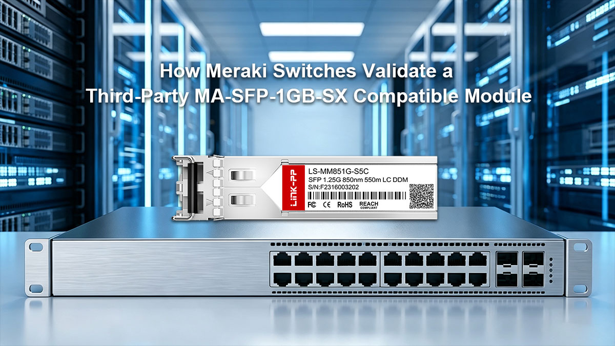
Comprendere come Meraki legge la codifica EEPROM di terze parti
Ogni modulo SFP contiene un minuscolo chip interno, noto come EEPROM, che memorizza dati di identificazione essenziali come il nome del fornitore, il codice articolo e il codice seriale. Quando viene inserito un ricetrasmettitore alternativo, lo switch Meraki interroga immediatamente questo chip tramite un'interfaccia seriale I²C. Lo switch legge specifici indirizzi di byte per determinare se l'hardware è conforme ai profili di configurazione Meraki richiesti.
Se la codifica della EEPROM non presenta le stringhe del fornitore o le firme crittografiche precise previste dal sistema operativo, l'hardware viene segnalato. I moduli di terze parti programmati correttamente replicano questi dati di configurazione specifici, byte per byte. Questa accurata progettazione garantisce che lo switch riconosca il modulo alternativo come pienamente conforme ai requisiti del proprio sistema nativo.
Cosa succede durante il processo di convalida dell'avvio dello switch?
Il momento critico della validazione si verifica all'avvio dello switch Meraki o quando un nuovo modulo viene sostituito a caldo in una porta attiva. Durante questa fase di inizializzazione, il sistema operativo dello switch si interrompe brevemente per eseguire lo script di verifica hardware sullo slot SFP. Lo script controlla i requisiti di alimentazione, stabilisce la segnalazione a livello fisico e verifica simultaneamente le chiavi di compatibilità della EEPROM.
Se lo script di validazione viene eseguito correttamente, lo switch abilita la porta e inizia a trasmettere il segnale ottico a 850 nm. Tuttavia, se il modulo non supera questa validazione all'avvio, lo switch potrebbe disabilitare completamente la porta o limitare alcune funzionalità diagnostiche avanzate. Questo controllo di sicurezza garantisce che l'hardware non verificato non possa compromettere inaspettatamente la stabilità complessiva della rete di switch.
Riconoscimento degli avvisi del pannello di controllo Meraki relativi a ottiche non verificate
Quando un modulo standard di terze parti non supera i controlli di verifica interni, la dashboard Meraki gestita tramite cloud ne segnala immediatamente lo stato. Gli amministratori visualizzeranno in genere un avviso ben visibile nella pagina delle porte dello switch che indica il rilevamento di un "cavo ottico non supportato" o di un "ricetrasmettitore non Meraki". Sebbene il collegamento possa comunque generare traffico, questo avviso funge da notifica ufficiale della mancanza di validazione nativa del modulo.
Oltre agli avvisi visivi, l'utilizzo di un modulo con codice errato può attivare log di sistema automatici che intasano la console di avviso di rete. In alcune versioni firmware restrittive, questi avvisi possono impedire al team di supporto Meraki di risolvere i problemi di collegamento a valle fino a quando non viene riconosciuto l'hardware completamente compatibile. Riconoscere questi specifici comportamenti del pannello di controllo consente di identificare rapidamente i moduli che non presentano un corretto allineamento del codice.
Come ottenere una vera compatibilità plug-and-play senza errori
Per evitare completamente questi problemi operativi, è necessario selezionare hardware alternativo pre-programmato con una compatibilità a livello di sistema impeccabile. I moduli MA-SFP-1GB-SX di terze parti di alta qualità garantiscono che la dashboard cloud rimanga sempre verde e priva di fastidiosi messaggi di errore.
Attenersi alle seguenti best practice di implementazione garantirà un'installazione plug-and-play senza errori:
- Prima di acquistare alternative di terze parti, verificare la codifica EEPROM specifica per Meraki.
- Assicurarsi che le stringhe di configurazione del fornitore corrispondano esattamente alle specifiche ufficiali del modulo MA-SFP-1GB-SX.
- Verificare il corretto allineamento delle funzionalità DOM per garantire la pulizia dei report nella dashboard.
- Eseguire un test di hot-swap su una porta non di produzione per verificare la presenza di errori immediati.
- Mantieni aggiornato il firmware dello switch in modo che i protocolli di convalida vengano eseguiti secondo le linee guida attuali del fornitore.
🌾 Test fisici e ottici per un modulo compatibile con MA-SFP-1GB-SX
Prima di implementare moduli ottici di terze parti in una rete di produzione attiva, è essenziale condurre rigorosi test fisici e ottici. Queste valutazioni hardware garantiscono che i componenti alternativi siano in grado di resistere alle sollecitazioni strutturali e di trasmettere i dati in modo pulito sulle fibre ottiche. Dedicare tempo all'ispezione e alla misurazione fisica dei componenti ottici previene la perdita di pacchetti e l'instabilità del collegamento in futuro.
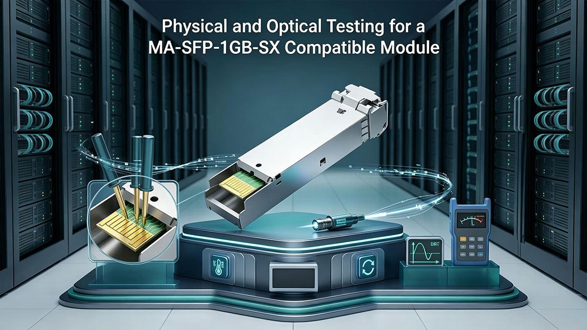
Test della porta LC duplex per il bloccaggio fisico sicuro
Un'interfaccia fisica allentata o di scarsa qualità su un modulo alternativo MA-SFP-1GB-SX può causare interruzioni intermittenti del collegamento a causa delle vibrazioni fisiche nel rack del server. La valutazione dell'integrità meccanica della porta Duplex LC garantisce una connessione salda e affidabile tra il vetro ottico e l'alloggiamento del ricetrasmettitore. Un accoppiamento fisico preciso previene disconnessioni accidentali del cavo e riduce al minimo le fluttuazioni del segnale durante il funzionamento.
Per garantire che il modulo stabilisca una connessione fisica sicura e stabile, concentrati su questi punti critici di ispezione:
- Quando inserisci il cavo patch in fibra ottica, fai attenzione a sentire un clic ben definito.
- Tirare delicatamente il connettore per verificare che il meccanismo di bloccaggio sia ben saldo.
- Verificare che la leva del gancio di fissaggio della balla si apra e si chiuda senza intoppi.
- Verificare le dimensioni del ricetrasmettitore rispetto ai fattori di forma standard degli slot SFP.
- Verificare che non vi siano oscillazioni eccessive una volta che il modulo è bloccato all'interno dell'interruttore.
Misurazione della perdita di inserzione ottica con una sorgente luminosa a 850 nm
La perdita di inserzione ottica (OLP) misura la quantità di potenza luminosa persa durante il passaggio del segnale attraverso le connessioni in fibra e l'interfaccia del ricetrasmettitore. Il metodo più preciso per verificare l'intensità del segnale consiste nel testare il modulo compatibile MA-SFP-1GB-SX di terze parti con un misuratore di potenza ottica a 850 nm dedicato. Mantenere la perdita di luce entro i limiti accettabili dal settore garantisce che i pacchetti di dati raggiungano la loro destinazione senza degrado.
Quando effettuate le misurazioni della perdita di inserzione, seguite questi passaggi di validazione strutturati:
- Pulire accuratamente tutte le estremità delle fibre prima di iniziare il test di potenza.
- Utilizza la tua sorgente luminosa come riferimento per stabilire un valore di potenza di base.
- Collega il modulo SFP alternativo al misuratore di potenza ottica.
- Verificare che la perdita totale rimanga al di sotto della soglia massima di decibel consentita.
- Documentare i valori in dB per future attività di risoluzione dei problemi di rete e per la definizione dei parametri di riferimento.
Verifica della stabilità del laser e della qualità del segnale sotto carico continuo
Un'alternativa di alta qualità al modulo MA-SFP-1GB-SX deve mantenere un'uscita ottica stabile anche in presenza di traffico di rete intenso per periodi prolungati. I componenti di bassa qualità spesso soffrono di deriva termica, che causa fluttuazioni di potenza del laser a 850 nm all'aumentare della temperatura interna. L'esecuzione di test di carico continuo aiuta a identificare i ricetrasmettitori scadenti che non funzionano correttamente in condizioni operative aziendali realistiche.
È possibile verificare la stabilità del laser a lungo termine e la qualità del segnale monitorando queste aree chiave di prestazione:
- Monitorare la potenza di trasmissione in tempo reale durante i periodi di trasmissione intensa.
- Verificare la presenza di cali improvvisi nei livelli di potenza ottica nell'arco di 24 ore.
- Analizzare la forma d'onda del segnale utilizzando un oscilloscopio ottico, se disponibile.
- Prestare attenzione a eventuali accumuli di calore localizzati intorno all'alloggiamento della porta dello switch SFP.
- Assicurarsi che la corrente di polarizzazione del laser rimanga entro le specifiche del produttore.
Verifica dei protocolli di pulizia per i connettori in fibra multimodale
Le particelle di polvere microscopiche sono la principale causa di problemi di prestazioni e danni permanenti al laser nelle reti in fibra multimodale. Poiché lo standard MA-SFP-1GB-SX si basa su un nucleo luminoso ampio, anche un minuscolo granello di detriti può bloccare o disperdere gravemente il fascio luminoso a 850 nm. L'adozione di rigorosi protocolli di pulizia prima dell'inserimento di qualsiasi cavo patch garantisce una trasmissione ottimale della luce e protegge il vostro investimento.
L'applicazione di questi semplici passaggi di pulizia massimizzerà le prestazioni ottiche ed eliminerà le interferenze con il segnale:
- Utilizzare un apposito pulitore a scatto per fibre ottiche progettato per connettori LC da 1.25 mm.
- Non toccare mai la superficie terminale della ghiera con le dita nude o con la pelle.
- Se possibile, ispezionate la punta del connettore con un microscopio a fibra ottica.
- Per le macchie d'olio ostinate, utilizzare salviette specifiche prive di lanugine e un solvente ottico.
- Chiudere immediatamente tutte le porte non utilizzate per impedire alla polvere ambientale di penetrare nelle ottiche.
🌾 Validazione della distanza e del cavo in fibra per il modulo MA-SFP-1GB-SX di terze parti
La validazione delle capacità di distanza di un ricetrasmettitore alternativo MA-SFP-1GB-SX è essenziale per prevenire la perdita di segnale a metà percorso nelle reti campus. Le diverse qualità del vetro multimodale influenzano notevolmente la distanza massima percorribile da un laser a 850 nm prima che i dati inizino a degradarsi. Un'analisi approfondita dell'infrastruttura di cablaggio fisica garantisce che un modulo di terze parti funzioni in modo impeccabile sia su brevi tratti che su lunghezze massime.

Test delle prestazioni alla portata massima di 550 m utilizzando cavi MMF da 50/125 µm
L'installazione di un modulo compatibile MA-SFP-1GB-SX di terze parti al suo limite fisico richiede un cablaggio multimodale di alta qualità da 50/125 µm, tipicamente classificato come OM2. Questi moderni tipi di fibra presentano un design del nucleo ottimizzato che consente ai segnali luminosi di viaggiare fino a 550 m senza un'attenuazione significativa. I test a questa distanza massima confermano se il ricetrasmettitore alternativo possiede la potenza ottica necessaria per collegamenti a lunga distanza tra edifici.
Durante i test di stress a portata massima, gli amministratori di rete dovrebbero cercare segnali di ritardi nella ricezione dei pacchetti o di instabilità intermittente del collegamento. Se il laser ottico di terze parti non è sufficientemente potente, la connessione si interromperà completamente o subirà un'eccessiva perdita di pacchetti in presenza di carichi di dati elevati. La verifica di una velocità di trasmissione stabile a 550 metri dimostra che l'hardware alternativo corrisponde alle reali capacità fisiche del modulo Meraki originale.
Comprensione dei limiti di distanza dei cavi MMF da 62.5/125 µm di vecchia generazione
Le infrastrutture di rete obsolete spesso contengono vecchi cavi patch in fibra multimodale da 62.5/125 µm, comunemente noti come fibra standard OM1. Quando si utilizza un modulo MA-SFP-1GB-SX di terze parti su fibra OM1, la distanza di trasmissione massima garantita si riduce drasticamente da 550 m a soli 275 m. Questa drastica riduzione è dovuta al fatto che il nucleo più ampio del vetro da 62.5 µm provoca livelli di dispersione della luce molto più elevati.
Il tentativo di estendere un collegamento Gigabit oltre la soglia dei 275 metri su cablaggi obsoleti comporterà l'immediata interruzione del collegamento o la corruzione dei pacchetti di dati. I team di rete devono pianificare attentamente la disposizione dei cablaggi strutturali per evitare di estendere accidentalmente questi collegamenti più datati. Comprendere questi limiti fisici dei supporti di trasmissione impedisce di attribuire ingiustamente la colpa a un ricetrasmettitore alternativo perfettamente funzionante.
Verifica dell'integrità del segnale su più pannelli di permutazione in fibra ottica
Negli ambienti aziendali, un singolo cavo in fibra ottica attraversa spesso diversi pannelli di permutazione e telai di distribuzione intermedi prima di raggiungere la sua destinazione finale. Ogni punto di connessione fisica introduce una piccola quantità di riflessione e attenuazione della luce che può rappresentare una sfida per un modulo MA-SFP-1GB-SX alternativo. La verifica dell'integrità complessiva del segnale richiede la misurazione della perdita ottica accumulata sull'intera rete di permutazione.
Se il collegamento multimodale attraversa troppi punti di connessione interconnessi, la perdita cumulativa di decibel potrebbe superare la soglia di sensibilità del ricevitore. L'utilizzo delle funzionalità DOM integrate nel modulo compatibile consente ai tecnici di visualizzare i livelli di potenza RX in tempo reale direttamente dalla dashboard di Meraki. Monitorare attentamente questi valori diagnostici garantisce che il routing multi-pannello non comprometta la stabilità della rete.
Identificazione e risoluzione dei problemi di dispersione modale su cavi di grandi dimensioni
La dispersione modale si verifica quando diversi raggi luminosi viaggiano lungo il nucleo di una fibra multimodale a velocità leggermente diverse, causando la dispersione dell'impulso ottico nel tempo. Quando si utilizza un modulo MA-SFP-1GB-SX alternativo su lunghe distanze, una forte dispersione modale può sovrapporre gli impulsi di dati e causare errori di bit. Questo fenomeno è una delle principali cause nascoste di prestazioni di rete lente su lunghe tratte di cavo.
Per identificare questo problema, i tecnici dovrebbero controllare i contatori di errore sulla porta dello switch Meraki per rilevare eventuali errori imprevisti nella sequenza di controllo del frame. Se la dispersione compromette la chiarezza del segnale, la sostituzione dei cavi patch più vecchi con cavi OM2 ottimizzati per laser di solito risolve il problema. Affrontare correttamente queste anomalie di dispersione garantisce che i ricetrasmettitori alternativi forniscano una trasmissione dati nitida, pulita e affidabile.
🌾 Benchmark delle prestazioni di rete per la convalida dell'alternativa MA-SFP-1GB-SX
Definire rigorosi benchmark di prestazioni di rete è la fase finale di verifica per garantire che un ricetrasmettitore ottico di terze parti sia in grado di gestire il traffico di produzione reale. Mentre i test fisici e ottici dimostrano la validità dell'hardware, i benchmark a livello dati confermano che il modulo trasmette i pacchetti senza introdurre colli di bottiglia. Il superamento di questi test di stress di rete standard garantisce che l'hardware alternativo offra la stessa velocità di trasmissione di un ricetrasmettitore Meraki originale.

Esecuzione di test di throughput a velocità di linea 1G (standard RFC 2544)
La validazione di un modulo MA-SFP-1GB-SX di terze parti richiede l'esecuzione di test conformi allo standard industriale RFC 2544 per valutarne le effettive capacità di inoltro dei pacchetti. Questo benchmark invia al collegamento ottico pacchetti di varie dimensioni, da piccoli pacchetti da 64 byte a grandi frame da 1518 byte, per verificare la presenza di perdite. Il raggiungimento di una velocità di trasmissione costante di 1 Gbps per tutte le dimensioni dei frame dimostra che il modulo è in grado di gestire un traffico universitario ad alta densità.
I ricetrasmettitori più economici e di scarsa qualità spesso faticano a gestire un flusso continuo di frame di piccole dimensioni, causando overflow del buffer imprevisti. Verificando che l'hardware alternativo raggiunga la massima capacità di velocità di linea senza perdere un singolo frame, si garantisce una perfetta integrazione nell'infrastruttura di commutazione. Questo test di throughput assicura che le prestazioni del piano dati rimangano completamente inalterate.
Misurazione del tasso di errore di bit (BER) per garantire zero perdita di pacchetti.
Il test del tasso di errore di bit (BER) è un metodo estremamente preciso utilizzato per misurare il rapporto tra i bit corrotti e il numero totale di bit trasmessi sul collegamento in fibra ottica. Durante la validazione di un modulo MA-SFP-1GB-SX alternativo, l'esecuzione di un test BER prolungato garantisce che il laser a 850 nm invii impulsi di dati perfettamente nitidi. Un collegamento di rete ideale deve mantenere un tasso di errore di bit pari a zero, ovvero nessun dato deve essere distorto lungo il percorso in fibra.
Se un ricetrasmettitore di terze parti utilizza componenti interni di qualità inferiore, può introdurre un lieve rumore elettronico che, nel tempo, corrompe i singoli bit di dati. Questa corruzione costringe lo switch Meraki a scartare i frame, con conseguente rallentamento delle prestazioni delle applicazioni e inspiegabile perdita di pacchetti. Confermare un punteggio BER impeccabile in condizioni di test rigorose garantisce stabilità del collegamento a lungo termine e una trasmissione del segnale pura.
Test della variazione del ritardo dei pacchetti e dei benchmark di latenza a pieno carico
La latenza di rete e la variazione del ritardo dei pacchetti, comunemente nota come jitter, sono parametri critici che influiscono direttamente sugli strumenti di comunicazione aziendale in tempo reale. Quando si valuta un modulo compatibile con MA-SFP-1GB-SX di terze parti, è importante misurare il tempo esatto impiegato dai dati per attraversare i componenti ottici. Mantenere la latenza a un livello minimo e costante garantisce che il traffico sensibile al tempo fluisca senza intoppi sulla rete dorsale.
Un jitter eccessivo o picchi improvvisi di latenza sono chiari indicatori di ritardi di elaborazione interni o di una scarsa sincronizzazione dell'orologio all'interno del ricetrasmettitore alternativo. Queste incongruenze temporali possono compromettere l'esperienza utente durante videoconferenze ad alta definizione e chiamate VoIP in tempo reale. Il benchmarking di questi parametri di latenza a pieno carico garantisce che il sistema ottico alternativo mantenga il traffico voce e video di rete perfettamente stabile.
Valutazione comparativa della stabilità dell'aggregazione di link (LACP) con moduli multipli
Il protocollo LACP (Link Aggregation Control Protocol) consente di raggruppare più porte fisiche MA-SFP-1GB-SX in un singolo canale logico ad alta larghezza di banda. Testare il comportamento di un gruppo di moduli alternativi all'interno di un bundle LACP attivo è fondamentale per convalidare la stabilità del bilanciamento del carico e il comportamento in caso di failover. I ricetrasmettitori raggruppati devono comunicare in perfetta sincronia per mantenere senza problemi la struttura del collegamento aggregato.
Se un modulo di terze parti presenta problemi di instabilità nella temporizzazione interna, può disconnettersi ripetutamente dal bundle e causare fluttuazioni dell'intero gruppo aggregato. L'esecuzione di failover manuali durante i test attivi consente di verificare che le ottiche alternative rimanenti gestiscano immediatamente il carico di traffico. La conferma della stabilità di LACP garantisce che i canali uplink ad alta capacità rimangano resilienti e pienamente operativi.
🌾 Validazione della compatibilità del modulo MA-SFP-1GB-SX con diversi modelli di switch Meraki MS
L'implementazione di un modulo ottico di terze parti richiede un'attenta validazione su diversi livelli hardware per garantire un comportamento uniforme della rete. La vasta gamma di switch Meraki gestisce l'inizializzazione del ricetrasmettitore in modo differente a seconda dell'architettura di elaborazione e del ruolo specifici del modello. Testare l'hardware su più livelli di implementazione conferma che il modulo ottico alternativo rimanga stabile nell'intera infrastruttura aziendale.
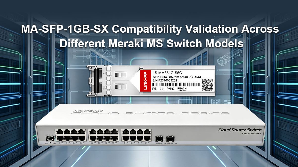
Test del modulo MA-SFP-1GB-SX su switch di livello di accesso (MS120/MS210)
Gli switch di accesso come i Meraki MS120 e MS210 fungono da punti di ingresso principali per i dispositivi degli utenti finali nella rete aziendale. L'installazione di un modulo compatibile con MA-SFP-1GB-SX di terze parti in questi switch di accesso offre una soluzione estremamente conveniente per stabilire collegamenti in fibra gigabit verso i rack di distribuzione. Test approfonditi su questi modelli garantiscono che i carichi di traffico giornalieri a livello di accesso non causino riavvii imprevisti delle porte o interruzioni del collegamento.
Poiché gli switch di livello di accesso sono distribuiti in gran numero su più piani, qualsiasi incompatibilità diffusa tra i ricetrasmettitori può causare gravi disagi agli utenti. Gli amministratori devono verificare che queste piattaforme di livello base leggano continuamente le statistiche DOM del modulo alternativo senza generare errori nel pannello di controllo. Garantire prestazioni impeccabili a questo livello assicura che la connettività di rete di base rimanga estremamente stabile per tutte le workstation connesse.
Verifica delle prestazioni su switch core e di aggregazione (serie MS400)
L'hardware di core e di aggregazione, come la serie Meraki MS400 ad alta capacità, richiede un livello di resilienza operativa molto più elevato a causa degli enormi volumi di dati aggregati che gestisce. L'utilizzo di un modulo ottico MA-SFP-1GB-SX alternativo a livello di core richiede la certezza assoluta che il modulo sia in grado di elaborare flussi di pacchetti intensi e continui. Un singolo guasto hardware a questo livello centrale della rete potrebbe isolare istantaneamente interi reparti o edifici.
I test su questi switch di fascia alta si concentrano principalmente sulle prestazioni termiche e sulla trasmissione dati ininterrotta in condizioni di massimo stress del sistema. Lo chassis dello switch principale tende a surriscaldarsi a causa della configurazione ad alta densità di porte, rendendo assolutamente indispensabile l'utilizzo di componenti transceiver interni di alta qualità. La verifica della compatibilità con la serie MS400 dimostra che i dispositivi ottici di terze parti sono sufficientemente robusti per supportare la dorsale di rete critica.
Validazione dell'interoperabilità sulle porte di stacking e uplink tra hardware Meraki
L'hardware Meraki utilizza porte di uplink e di stacking dedicate per collegare più chassis di switch fisici in un'unica unità di gestione integrata. L'implementazione di un'alternativa di terze parti MA-SFP-1GB-SX in questi slot ad alta priorità richiede una precisa sincronizzazione temporale e la compatibilità del protocollo. I transceiver alternativi devono essere in grado di trasportare il traffico del piano di controllo tra gli switch insieme ai pacchetti di dati utente standard senza introdurre alcuna latenza.
Se un componente ottico alternativo presenta un comportamento di segnalazione anomalo su una porta di stacking o uplink attiva, l'intero stack logico dello switch potrebbe risultare instabile o disconnesso. I test dovrebbero includere failover forzati e cicli di sincronizzazione della configurazione per verificare come l'hardware di terze parti reagisce a improvvisi cambiamenti di stato. Confermare la perfetta interoperabilità su queste porte di backbone garantisce che l'architettura dello switch espansa si comporti come una rete unificata e altamente resiliente.
🌾 Verdetto finale sulla convalida dell'alternativa compatibile di terze parti MA-SFP-1GB-SX
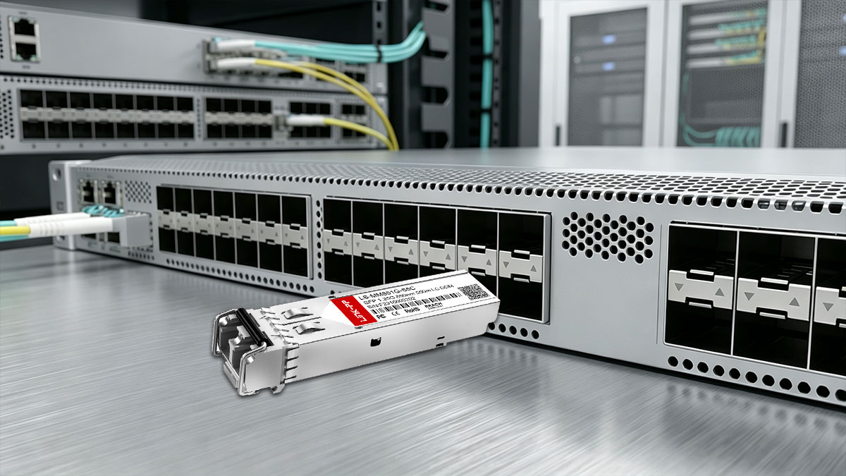
La validazione di un modulo compatibile MA-SFP-1GB-SX di terze parti dimostra che i team di rete non devono necessariamente spendere cifre esorbitanti per hardware OEM al fine di mantenere un'infrastruttura ad alte prestazioni. Quando un transceiver alternativo supera rigorosi controlli a livello fisico, di decodifica EEPROM e benchmark prestazionali, offre la stessa affidabilità operativa di un modulo originale. Investire tempo in una validazione strutturata fin dalle prime fasi garantisce la stabilità della rete a lungo termine, riducendo drasticamente i costi complessivi di implementazione dell'hardware.
Per garantire che la soluzione ottica scelta rimanga completamente affidabile e priva di errori nel tempo, tenete a mente questi punti chiave per l'implementazione finale:
- Assicurarsi sempre che la lunghezza d'onda di 850 nm e le specifiche 1000BASE-SX corrispondano esattamente.
- Conferma la programmazione premium della EEPROM per bypassare completamente gli avvisi del cruscotto Meraki.
- Pulire accuratamente tutti i connettori in fibra multimodale prima di inserirli fisicamente nelle porte.
- Monitora regolarmente le metriche DOM in tempo reale per individuare tempestivamente potenziali guasti ai collegamenti.
- Prima di un'implementazione completa, testate i nuovi lotti di hardware su porte di accesso non critiche.
Pronti a ottimizzare il budget di rete senza compromettere le prestazioni aziendali e la diagnostica cloud? Per un'implementazione affidabile che soddisfi senza problemi tutti i rigorosi requisiti hardware sopra descritti, valutate l'opportunità di esplorare alternative compatibili come la soluzione progettata con cura. LINK-PP Modulo SFP LS-MM851G-S5C 1000BASE-SX. Puoi trovare questo ricetrasmettitore completamente conforme o sfogliare altre soluzioni ottiche affidabili visitando il sito LINK-PP Negozio ufficiale.