

























As 10G Ethernet continues to support campus networks, enterprise infrastructure, and longer-distance interconnections, optical transceiver performance has become increasingly important. For extended-reach links, simply establishing a 10Gbps connection is not enough to confirm that the network is operating efficiently. Fiber attenuation, optical power, switch configuration, and endpoint performance can all influence the throughput that users actually experience.
The Aruba J9153D is designed for 10G optical connectivity over extended distances, making its real-world performance an important consideration when planning or evaluating 10G ER links. While its nominal link rate indicates 10Gbps Ethernet capability, actual throughput can vary depending on the complete optical and network environment. A proper J9153D review therefore needs to examine both the transceiver's technical characteristics and the conditions under which throughput is tested.
This article provides a practical technical review of J9153D performance in 10G ER deployments, covering:
- J9153D technical and optical characteristics
- 10G ER link architecture and optical budget
- Throughput testing methodology and expected results
- Factors that can affect real-world performance
- Compatibility, troubleshooting, and deployment considerations
By connecting these factors, the article helps network professionals interpret J9153D throughput results more accurately and determine whether performance issues originate from the transceiver, fiber infrastructure, network equipment, or test environment.
🏮 J9153D Overview and Technical Characteristics
The J9153D is a 10G SFP+ optical transceiver intended for extended-reach Ethernet connectivity, with its performance determined by the interaction between the module's optical characteristics and the surrounding network infrastructure. Understanding its core specifications is therefore the first step in evaluating how it performs in a 10G ER link.
What Is the J9153D?
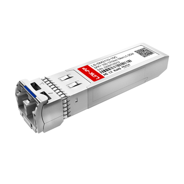
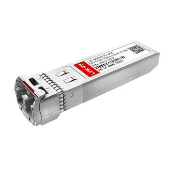
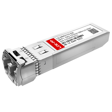
The Aruba J9153D is a 10G optical transceiver used to provide high-speed Ethernet connectivity over fiber. Its SFP+ form factor allows it to be installed directly into compatible 10G switch ports, while its extended-reach optical design makes it suitable for links that exceed the practical range of short-reach multimode solutions.
In a typical deployment, the J9153D provides the optical interface between an Aruba networking device and a remote 10G Ethernet endpoint. Its primary characteristics include:
- 10G Ethernet connectivity through an SFP+ interface
- Extended-distance optical transmission
- Fiber-based connectivity for reduced dependence on copper cabling
- Use in point-to-point network links between compatible 10G interfaces
- Application in enterprise, campus, and infrastructure networks where longer optical reach is required
The distinction between J9153D and shorter-reach optics is particularly important. A transceiver designed for extended-distance connectivity must maintain an adequate optical margin across the entire fiber path, including fiber attenuation, connector loss, and other passive components.
J9153D Key Optical and Electrical Specifications
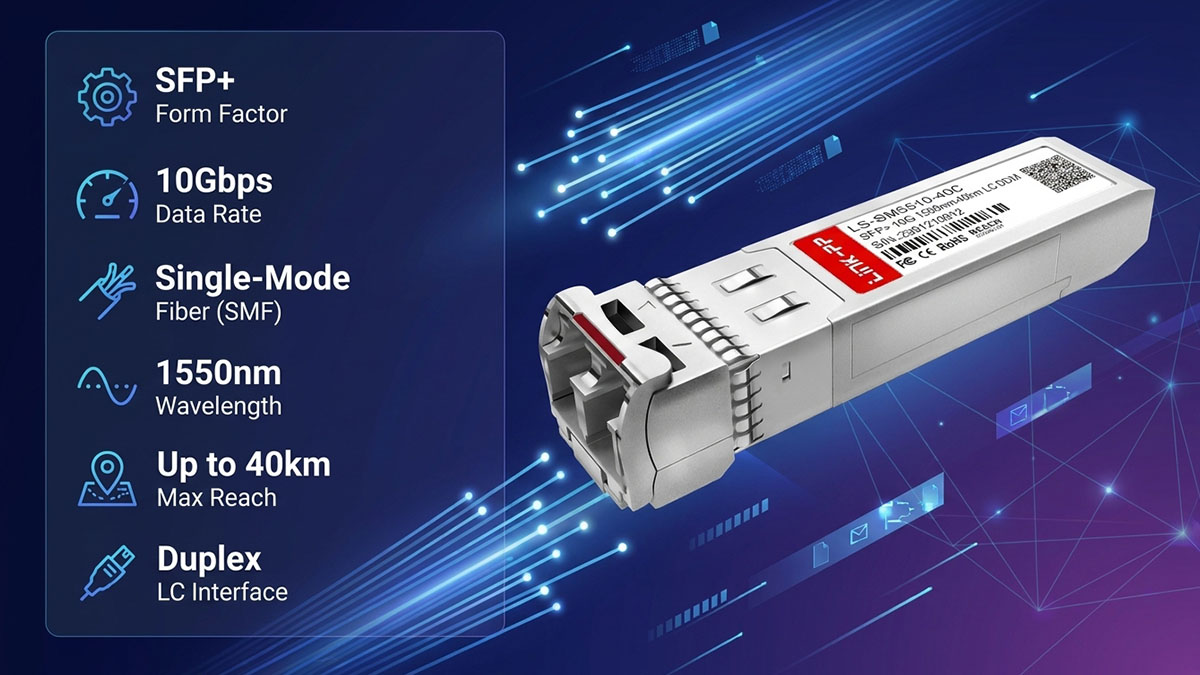
The most relevant J9153D specifications are those that define its data rate, optical interface, transmission characteristics, and physical integration with the host device. These parameters provide the baseline for determining whether the module is appropriate for a specific 10G fiber link.
| Parameter | J9153D Characteristic | Deployment Relevance |
|---|---|---|
| Form Factor | SFP+ | Fits compatible 10G SFP+ ports |
| Data Rate | 10Gbps | Defines the nominal Ethernet link rate |
| Fiber Type | Single-mode fiber (SMF) | Supports extended-reach optical transmission |
| Wavelength | 1550nm | Determines the optical transmission band |
| Transmission Distance | Up to 40km | Suitable for long-distance 10G links |
| Interface | Duplex LC | Requires compatible dual-fiber connectivity |
These specifications should be considered as a complete set rather than independently. For example, the rated transmission distance only has practical meaning when the installed fiber path, connectors, and optical loss remain within the module's available link budget.
Which J9153D Specifications Affect Throughput?
J9153D's nominal 10Gbps rate establishes the physical Ethernet link capability, but it does not guarantee that an application will record exactly 10Gbps of usable throughput. Actual performance depends on the optical link, switching equipment, endpoints, and traffic characteristics.
The specifications and conditions most directly related to throughput include:
- Data rate: Establishes the maximum nominal Ethernet signaling rate.
- Transmission distance: Longer fiber paths introduce greater attenuation and can reduce optical margin if the link approaches its design limit.
- Optical wavelength: Determines how the module interacts with the fiber and other optical components in the path.
- Fiber type: The installed SMF must be appropriate for the J9153D's optical characteristics and intended reach.
- Optical power budget: Determines whether sufficient received optical power remains after fiber and connection losses.
- Receiver sensitivity: Influences the minimum optical signal level required for reliable reception.
A healthy J9153D link should maintain stable 10Gbps Ethernet operation when these optical parameters are properly matched. If throughput is substantially below the expected level, however, the module's nominal specification alone cannot identify the cause; fiber condition, interface configuration, endpoint processing, and traffic-generation equipment must also be examined.
🏮 How J9153D Supports 10G ER Links
The J9153D supports 10G ER connectivity by converting electrical 10G Ethernet signals from a compatible SFP+ port into optical signals that can travel across single-mode fiber over extended distances. Stable 10Gbps operation depends on maintaining sufficient optical margin throughout the complete link, from the transmitting port to the receiving endpoint.
J9153D 10G ER Link Architecture
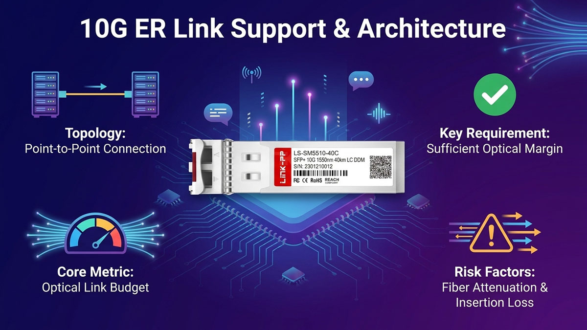
A typical J9153D 10G ER deployment uses compatible optical transceivers at both ends of a point-to-point fiber connection. The switch or network device provides the electrical Ethernet interface, while the J9153D handles optical transmission and reception across the fiber path.
A basic link consists of:
- 10G-capable Aruba switch port: Provides the host-side SFP+ interface for the J9153D.
- J9153D transceiver: Converts electrical Ethernet data into optical signals and converts received optical signals back into electrical data.
- Single-mode fiber: Carries the optical signal between the two network locations.
- Duplex LC connections: Provide separate optical paths for transmission and reception.
- Remote 10G endpoint: Receives the optical signal through a compatible 10G optical interface.
This architecture separates the optical transmission function from the switching and traffic-processing functions. Consequently, a J9153D link can show a normal 10Gbps interface state while actual traffic throughput is still affected by the fiber path, switch configuration, or endpoint capabilities.
Optical Link Budget and Reach
The J9153D's extended reach depends on maintaining enough optical power at the receiver after accounting for all losses along the fiber path. The rated reach should therefore be evaluated together with fiber attenuation, connector losses, splice losses, and the module's transmitter and receiver characteristics.
The main components of an optical link budget include:
- Transmitter output power: The optical power launched by the J9153D at the transmitting end.
- Fiber attenuation: Optical power lost as the signal travels through the single-mode fiber.
- Connector and splice losses: Additional attenuation introduced by LC connectors, patch panels, adapters, and splices.
- Receiver sensitivity: The minimum optical power required by the receiving module for reliable signal detection.
- Remaining optical margin: The difference between available received power and the minimum level required by the receiver.
A sufficient margin is important because a link operating very close to its optical limit can become more sensitive to connector contamination, fiber degradation, temperature changes, or additional patching. For this reason, maximum reach should be treated as a design limit rather than automatically as the preferred deployment distance.
Factors That Can Limit 10G ER Throughput
A J9153D link can maintain a 10Gbps negotiated rate while delivering lower-than-expected traffic throughput if the physical or logical environment is not properly configured. The most useful approach is to examine the complete transmission path rather than immediately attributing poor performance to the transceiver.
Common limiting factors include:
- Excessive insertion loss: High loss from connectors, patch panels, or splices can reduce optical margin.
- Poor fiber quality: Damaged, degraded, or unsuitable fiber can introduce attenuation or signal instability.
- Contaminated connectors: Dust or debris on optical interfaces can significantly affect received optical power.
- Incorrect fiber type: Cabling that does not match the module's intended optical characteristics can prevent the expected reach and performance.
- Insufficient optical margin: A link close to its power limit may experience errors or instability under demanding conditions.
- Duplex polarity problems: Incorrect TX/RX orientation can prevent normal bidirectional communication.
- Unsupported configurations: Host-platform or transceiver compatibility issues can affect link operation and monitoring.
- Switch-side limitations: Port configuration, interface errors, traffic policies, or hardware constraints can become the actual throughput bottleneck.
Therefore, evaluating J9153D performance in a 10G ER environment requires more than checking whether the link is active. Optical health, cabling, port configuration, and end-to-end traffic behavior should all be considered before drawing conclusions about throughput.
🏮 J9153D Throughput Testing Methodology
A reliable J9153D throughput test should evaluate the entire 10G ER link rather than the transceiver in isolation. The test should first confirm stable 10Gbps link establishment and healthy optical conditions, then measure traffic performance under controlled TCP and UDP workloads.
Test Environment and Network Topology
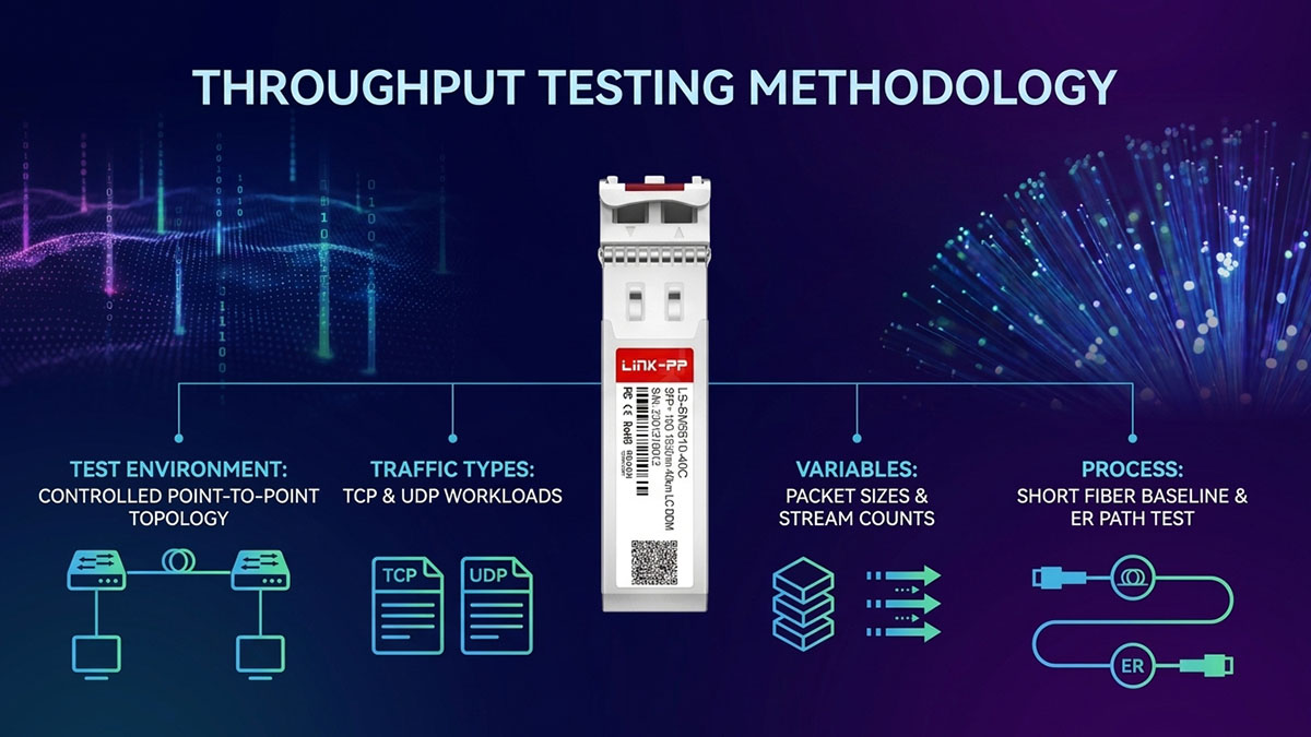
A controlled point-to-point topology provides the clearest way to evaluate J9153D performance because it minimizes unrelated variables. Both ends should use compatible 10G interfaces, with the J9153D modules connected through the intended single-mode fiber path.
A practical test environment should include:
- Two 10G-capable network interfaces or switches.
- J9153D transceivers installed at both endpoints.
- Compatible single-mode fiber and duplex LC connections.
- A traffic-generation or network benchmarking tool.
- Hosts with sufficient CPU and NIC performance to sustain 10Gbps traffic.
- Consistent switch configuration at both ends.
- Documented firmware, MTU, interface settings, and optical conditions.
Before generating traffic, verify that the interfaces establish a stable 10Gbps connection. This initial check prevents a physical-layer or configuration problem from being incorrectly interpreted as a throughput limitation.
The test should also begin with a known-good reference path where possible. A short fiber connection can establish a baseline, making it easier to determine whether later performance changes are associated with the extended optical path.
Throughput Test Parameters
J9153D performance should be tested under multiple traffic conditions because a single benchmark does not fully represent 10G Ethernet behavior. Packet size, protocol, stream count, and traffic direction can all influence measured throughput.
Important test parameters include:
- Link speed: Confirm 10Gbps operation before every test series.
- Packet size: Test different packet sizes to identify packet-processing limitations.
- TCP traffic: Evaluate practical throughput while accounting for congestion control and retransmissions.
- UDP traffic: Examine packet loss and forwarding capacity under controlled offered loads.
- Single-stream traffic: Identify limitations associated with one TCP or UDP flow.
- Multi-stream traffic: Determine whether parallel flows can better utilize the available 10G link.
- Bidirectional traffic: Test simultaneous transmission and reception.
- Test duration: Use sufficiently long runs to identify instability rather than relying on short bursts.
- Repeated measurements: Run each condition multiple times to improve result consistency.
These parameters should be recorded alongside throughput rather than reporting a single Mbps or Gbps figure. This provides useful context when comparing J9153D results across different network configurations.
How to Measure J9153D Throughput Accurately
Accurate J9153D testing requires a progressive workflow that separates link validation, optical verification, and traffic benchmarking. This prevents host-side limitations or physical-layer errors from being mistaken for transceiver performance.
A practical measurement sequence is:
- Confirm link establishment: Verify that both interfaces operate at the expected 10Gbps rate.
- Check optical conditions: Review available DOM information, including optical power and relevant module operating values.
- Inspect interface counters: Check for CRC errors, packet drops, link flaps, or other abnormalities before testing.
- Establish a baseline: Run the benchmark through a short, known-good fiber path.
- Test the ER path: Repeat the same workload through the intended extended-distance fiber connection.
- Compare traffic results: Record throughput, packet loss, retransmissions, and latency where applicable.
- Repeat under different workloads: Compare packet sizes, TCP/UDP traffic, and single- versus multi-stream performance.
- Check host utilization: Monitor CPU and NIC utilization to determine whether the endpoint is limiting the result.
The comparison between a reference connection and the actual ER path is particularly useful. If both configurations produce similar results while the ER link remains free of errors and has adequate optical margin, the J9153D-based optical path is less likely to be the source of a throughput limitation. Conversely, a significant performance difference should trigger further examination of fiber loss, connectors, optical power, and interface counters before changing application settings.
🏮 J9153D 10G ER Throughput Test Results
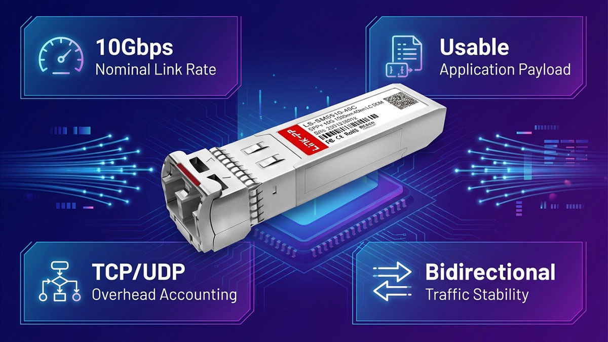
J9153D throughput results should be interpreted against the 10Gbps Ethernet line rate while accounting for protocol overhead, endpoint capability, and optical-link conditions. A properly functioning 10G ER link should deliver stable, near-line-rate network performance when the transceiver, fiber path, switch ports, and test hosts are correctly configured.
Expected Throughput on a Healthy 10G ER Link
A healthy J9153D link should negotiate at 10Gbps and provide consistent high throughput during sustained traffic tests. However, a benchmark should not be expected to report exactly 10Gbps of application-level payload because Ethernet framing, transport protocols, operating-system processing, and test-tool overhead consume part of the available bandwidth.
When evaluating results, consider the following points:
- 10Gbps link rate: Represents the nominal Ethernet interface speed rather than usable application payload.
- TCP throughput: Can vary with window size, congestion control, latency, CPU performance, and retransmissions.
- UDP throughput: Can approach the available link capacity but should also be evaluated alongside packet loss.
- Packet size: Larger packets generally reduce packets-per-second processing requirements, while smaller packets can place greater demands on CPUs and network interfaces.
- Test equipment: The benchmark host or traffic generator must have sufficient processing and NIC capability to drive sustained 10G traffic.
Therefore, a result slightly below the theoretical 10Gbps line rate is not, by itself, evidence of a J9153D problem. More important indicators are whether throughput remains stable, whether errors or retransmissions increase, and whether performance changes substantially when the ER fiber path is introduced.
Throughput Performance Across Different Test Conditions
Comparing results under controlled conditions provides more useful information than relying on a single throughput figure. The following framework can be used to evaluate a J9153D-based 10G ER link without attributing every variation to the optical module.
| Test Condition | Key Metric | Expected Observation |
|---|---|---|
| Short reference fiber | Throughput | Baseline performance with minimal optical-path loss |
| Extended single-mode link | Throughput | Similar performance when optical margin remains sufficient |
| High packet-rate workload | CPU/pps | Greater processing demand, especially with smaller packets |
| Bidirectional traffic | Aggregate throughput | Tests simultaneous TX/RX handling under sustained load |
The most important comparison is between the short reference path and the intended extended-reach path. If both produce comparable throughput and the ER connection shows no abnormal errors or optical-power conditions, increasing fiber distance within the supported design range should not inherently reduce the Ethernet link rate.
A noticeable difference between the two test paths requires additional investigation. In particular, increased optical attenuation, connector loss, or marginal received power can indicate that the physical layer deserves attention before conclusions are drawn from the traffic benchmark.
Interpreting Throughput Variations
Throughput variation should be analyzed together with packet loss, retransmissions, interface errors, and optical diagnostics. A lower benchmark result does not automatically indicate insufficient J9153D optical performance because the bottleneck may exist elsewhere in the network or test system.
Use the following relationships when interpreting results:
- Low throughput + clean interface counters: Investigate host CPU, NIC performance, TCP configuration, packet size, or traffic-generation capability.
- Low throughput + TCP retransmissions: Examine packet loss, latency, congestion, and physical-link stability.
- Low throughput + CRC or interface errors: Prioritize fiber, connectors, transceiver condition, and physical-layer troubleshooting.
- Throughput degradation with extended distance: Compare received optical power and total link loss against the available optical margin.
- Unstable throughput + link flaps: Check optical conditions, connectors, fiber integrity, and switch-side configuration.
- Good single-stream results but lower multi-stream performance: Investigate host processing, traffic-generation software, or network-stack behavior.
This approach prevents a common testing mistake: treating throughput as an isolated measurement of the J9153D itself. The most meaningful J9153D review compares repeatable results under identical conditions and correlates traffic performance with the physical-layer status of the complete 10G ER link.
🏮 J9153D Performance Factors in Real-World 10G ER Deployments
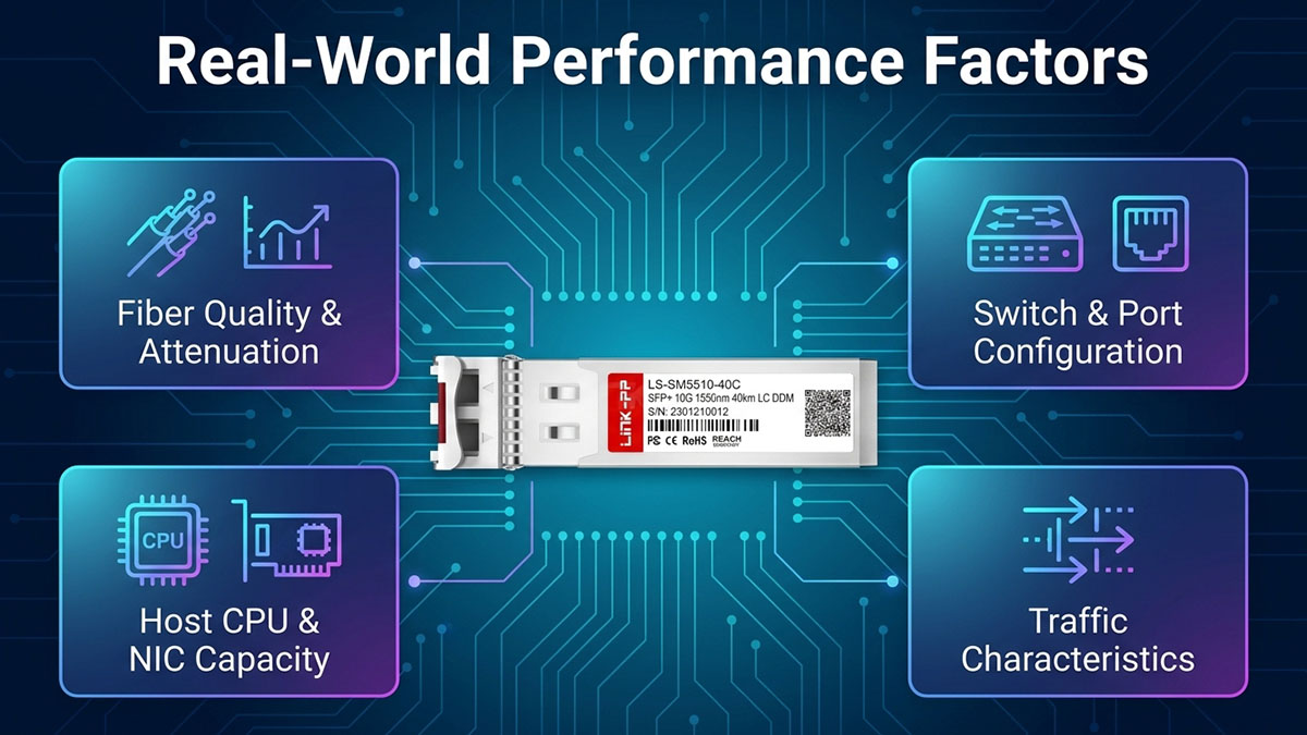
J9153D performance in a real-world 10G ER deployment depends on the complete network path rather than the transceiver alone. Fiber quality, optical attenuation, switch configuration, and host-side traffic processing can all determine whether a link maintains stable 10Gbps-class throughput under sustained workloads.
Fiber Quality and Optical Attenuation
Fiber quality directly affects the optical margin available to a J9153D link, particularly as transmission distance increases. A clean, properly installed single-mode fiber path helps preserve received optical power and reduces the risk of errors or instability.
The main physical-layer factors to evaluate include:
- Fiber attenuation: Optical loss increases with transmission distance and must remain within the available link budget.
- Connector insertion loss: Each LC connector, adapter, or patch-panel connection introduces additional loss.
- Splice loss: Poorly performed or excessive splices can reduce available optical margin.
- Bend-induced loss: Tight bends or improper cable routing can increase attenuation and affect signal quality.
- Connector cleanliness: Dust and contamination can increase insertion loss and reduce received optical power.
- Fiber condition: Damaged or degraded cabling can introduce intermittent performance problems that may appear as throughput instability.
These factors become particularly important when the link operates close to its maximum optical reach. A J9153D connection may remain operational while having insufficient margin for consistently reliable high-load traffic, so physical-layer inspection should precede more complicated performance tuning.
Switch and Port Configuration
The switch configuration determines how the J9153D interface interacts with the Ethernet network. A correctly installed module can still produce unexpected throughput results if the host port, MTU, flow control, or other interface settings are inappropriate.
Key configuration items include:
- Confirm that the switch port supports the required 10G SFP+ operation.
- Verify that the interface is operating at the expected speed and duplex mode.
- Review auto-negotiation behavior where applicable.
- Check MTU settings at both endpoints.
- Review flow-control configuration when analyzing packet drops or congestion.
- Inspect interface counters for CRC errors, drops, and other abnormalities.
- Check for link flaps or repeated interface resets.
- Ensure that traffic policies or QoS settings are not unintentionally restricting throughput.
Configuration consistency is especially important when testing throughput because the test should measure the optical link rather than an accidental switch-side bottleneck. If the J9153D link establishes normally but benchmark results remain unexpectedly low, the interface configuration should be validated before replacing optical components.
Traffic Characteristics and Host Limitations
The traffic workload can significantly influence measured J9153D throughput even when the optical link is operating normally. A benchmark result therefore reflects both network transmission capability and the ability of the endpoints to generate, process, and receive traffic at 10G speeds.
Important host-side variables include:
- TCP window and congestion control: These can affect how efficiently a TCP stream fills the available bandwidth.
- Packet size: Smaller packets increase packets-per-second requirements and can place greater pressure on CPU resources.
- Number of parallel streams: Multiple streams may achieve higher aggregate throughput when a single flow is limited by host or protocol behavior.
- NIC capabilities: The network adapter must be capable of sustaining the required 10G traffic rate.
- CPU utilization: High processor usage can prevent the host from generating or processing traffic fast enough.
- Storage performance: File-transfer tests may be limited by disk or storage throughput rather than the network.
- Application behavior: Real workloads can behave differently from synthetic traffic generated by benchmarking tools.
For this reason, a lower application-level result should not immediately be interpreted as a J9153D optical limitation. Comparing controlled TCP and UDP tests, monitoring CPU and NIC utilization, and checking interface statistics can help determine whether the constraint originates in the optical path or elsewhere in the end-to-end system.
🏮 Troubleshooting Low J9153D Throughput
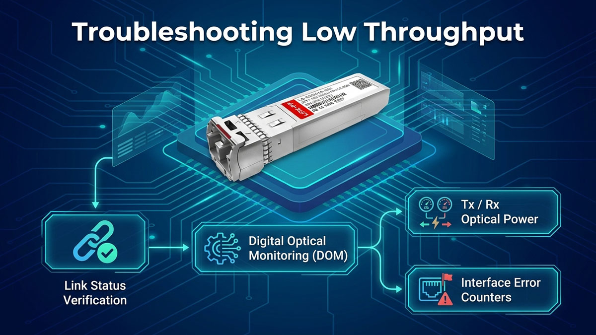
Low J9153D throughput should be diagnosed from the physical layer upward, starting with link status and interface errors before investigating host or application performance. This approach helps determine whether the problem originates from the optical path, switch configuration, transceiver condition, or traffic-generation environment.
Check Link Status and Interface Errors
The first troubleshooting step is to verify that the J9153D connection is operating consistently at the expected 10Gbps rate and that the interfaces are not reporting abnormal errors. A stable link with clean counters provides a necessary baseline for further throughput analysis.
Check the following items on both endpoints:
- Confirm the interface is up and operating at 10Gbps.
- Check for CRC or input errors.
- Review packet-drop counters.
- Look for output errors or excessive retransmissions where available.
- Check for link flaps or repeated interface resets.
- Compare local and remote interface statistics.
- Confirm that error counters do not increase rapidly during a sustained throughput test.
If the link remains at 10Gbps but throughput is low while interface counters stay clean, the problem may be outside the optical layer. Host CPU utilization, NIC performance, TCP behavior, packet size, and traffic-generation software should then be examined.
Verify J9153D Optical Diagnostics
Optical diagnostics can provide valuable evidence when throughput degradation occurs on an extended-reach link. Where digital optical monitoring is available, compare the J9153D's operating values with its normal operating range and look for abnormal readings.
Important diagnostic values include:
- Tx optical power: Indicates the optical power being transmitted into the fiber.
- Rx optical power: Shows the optical signal level received at the opposite end.
- Temperature: Helps identify abnormal module operating conditions.
- Voltage: Can reveal unusual host-side or module operating conditions.
- Alarm or warning status: May identify values approaching specified operating limits.
Rx optical power deserves particular attention when troubleshooting an ER connection. A significantly weaker received signal can indicate excessive fiber attenuation, connector loss, poor splicing, or other physical-path problems.
However, DOM readings should not be evaluated in isolation. A normal-looking value does not eliminate every possible fiber or transceiver issue, while an abnormal reading provides a reason to inspect the optical path more closely.
Isolate the Source of the Throughput Problem
The most effective troubleshooting method is to change one variable at a time and compare the resulting throughput. A short, known-good reference connection is especially useful because it establishes whether the problem follows the J9153D modules or appears only when the extended fiber path is introduced.
Follow this sequence:
- Test a short known-good fiber connection to establish a baseline.
- Verify both J9153D modules are properly recognized and operating normally.
- Inspect and clean optical connectors before reconnecting the ER path.
- Measure or estimate fiber attenuation and compare the result with the available optical budget.
- Test a different switch port to exclude a port-specific hardware or configuration issue.
- Validate NIC and host performance by monitoring CPU utilization and network-interface statistics.
- Repeat TCP and UDP tests to distinguish transport behavior from basic packet-forwarding performance.
- Compare single-stream and multi-stream results to identify host or protocol limitations.
The comparison between the reference path and the extended-reach path is the key diagnostic indicator. If throughput is healthy on the reference connection but falls significantly on the ER path, investigate fiber loss, connectors, optical power, and physical-layer errors first. If both paths produce similar low results, attention should shift toward the switch, NIC, host, traffic generator, or network configuration rather than assuming the J9153D is responsible.
🏮 Is J9153D Suitable for 10G ER Throughput Applications?
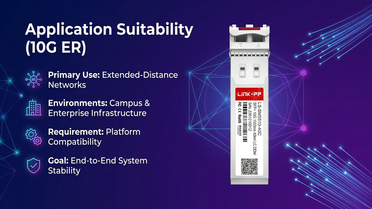
The J9153D can be suitable for 10G ER throughput applications when the optical reach, fiber infrastructure, compatible network equipment, and endpoint performance are properly matched. Its suitability should be judged by stable end-to-end throughput and optical-link health rather than by the 10Gbps interface rate alone.
Key Strengths of J9153D
The main advantage of J9153D is its ability to support extended-distance 10G optical connectivity while using the compact SFP+ form factor. This makes it relevant to network environments where a short-reach optic cannot provide the required fiber distance.
Key strengths include:
- 10G Ethernet connectivity: Provides a nominal 10Gbps interface for compatible network equipment.
- Extended optical reach: Supports longer-distance fiber connections than typical short-reach 10G optics.
- Single-mode fiber operation: Makes the module appropriate for infrastructure based on SMF.
- SFP+ form factor: Allows integration with compatible 10G SFP+ switch ports.
- Stable performance potential: With adequate optical margin and a properly configured network, the link can maintain consistent high-speed traffic performance.
- Diagnostic visibility: Where supported by the host platform, optical monitoring can help evaluate operating conditions during deployment and troubleshooting.
These characteristics make J9153D particularly relevant when network designers need to extend 10G Ethernet connectivity without changing to a different interface form factor.
Key Limitations to Consider
J9153D's suitability also depends on conditions outside the transceiver itself. A module can meet its nominal specifications while the complete link still produces lower-than-expected throughput because of fiber loss, configuration issues, or endpoint limitations.
Important limitations include:
- Actual throughput is end-to-end: A 10Gbps link rate does not guarantee exactly 10Gbps of application payload.
- Optical reach depends on link conditions: Maximum rated distance must be evaluated together with fiber attenuation, connector loss, and available optical margin.
- Platform compatibility matters: The target Aruba equipment must support the module and its intended operating configuration.
- Cabling quality affects performance: Contaminated connectors, excessive bends, poor splices, or damaged fiber can reduce optical performance.
- Test equipment can become the bottleneck: CPU, NIC, operating-system networking, and traffic-generation capabilities can limit measured throughput.
- Extended links require monitoring: Optical power and interface-error trends should be checked when stable long-distance operation is important.
These limitations mean that J9153D should be evaluated as part of a complete optical and Ethernet system. Replacing the transceiver alone may not resolve a throughput problem if the actual constraint is located elsewhere in the link.
When J9153D Is a Practical Choice
J9153D is most practical when the required network distance and existing fiber infrastructure align with its extended-reach optical characteristics. It is especially relevant for environments that need stable 10G connectivity across longer fiber paths.
Suitable scenarios include:
- Extended-distance 10G Ethernet links between network locations.
- Campus network interconnections requiring longer optical reach.
- Enterprise infrastructure links using existing single-mode fiber.
- Data-center or infrastructure connections where short-reach multimode optics are insufficient.
- Point-to-point links where consistent 10G performance is required across an extended optical path.
- Deployments where optical diagnostics and interface monitoring can be used to maintain link health.
Overall, J9153D is a reasonable option for 10G ER applications when its optical specifications match the installed fiber path and the host equipment supports the required configuration. The strongest indicator of suitability is not simply whether the link comes up, but whether it maintains stable throughput, acceptable optical margin, and clean interface statistics under the intended workload.
🏮 Conclusion
The J9153D can provide a practical foundation for extended-reach 10G Ethernet connectivity when its optical characteristics, fiber infrastructure, network equipment, and endpoint capabilities are properly matched. Evaluating J9153D performance should go beyond confirming a 10Gbps link and instead consider sustained throughput, optical power, fiber loss, interface errors, and real-world traffic conditions.
The key points to remember are:
- 10G capability: J9153D supports high-speed Ethernet connectivity through an SFP+ interface.
- ER performance: Stable throughput depends on sufficient optical margin across the complete fiber path.
- Testing: Reliable results require controlled TCP/UDP testing, repeated measurements, and appropriate host hardware.
- Troubleshooting: Low throughput should be investigated across the transceiver, fiber, switch, NIC, and traffic environment.
- Deployment: Platform compatibility, fiber quality, connector condition, and ongoing optical monitoring all contribute to long-term performance.
For network professionals evaluating J9153D-compatible optical solutions, understanding these factors can make transceiver selection and 10G ER deployment more predictable. The LINK-PP Official Store provides compatible optical networking solutions that can be considered when planning or expanding high-speed fiber infrastructure.