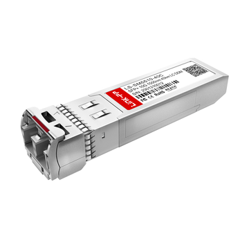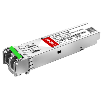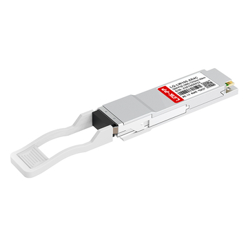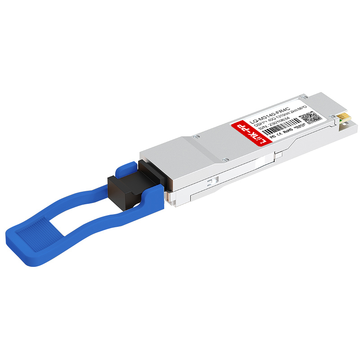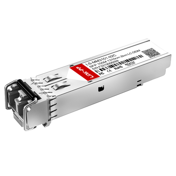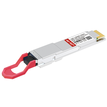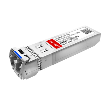
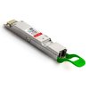
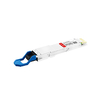
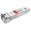
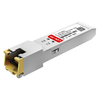
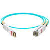
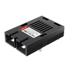
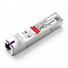
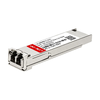






Cisco switches support a wide range of optical transceivers, including SFP, SFP+, SFP28, QSFP+, and QSFP28 modules. However, network administrators may encounter an "Unsupported Transceiver" error when installing third-party optical modules or using transceivers that do not match the switch's compatibility requirements. This warning can prevent a port from establishing a link, trigger an err-disable condition, or indicate that the switch cannot properly identify the installed module.
The issue is not necessarily caused by a defective optical transceiver. Cisco switch compatibility policies, EEPROM identification, IOS/IOS XE versions, port specifications, and physical installation conditions can all contribute to transceiver recognition problems. Understanding these factors is essential for identifying the actual cause and restoring normal network connectivity without making unnecessary configuration changes.
This guide explains how to troubleshoot the Cisco Unsupported Transceiver error, from initial diagnosis to compatibility verification and practical solutions. Specifically, it covers:
-
Common Cisco unsupported transceiver messages and their meanings.
-
CLI commands for identifying modules and diagnosing interface problems.
-
Step-by-step troubleshooting procedures and configuration considerations.
-
Ways to prevent compatibility issues with third-party optical modules.
-
LINK-PP Cisco-compatible optical transceivers and their compatibility verification process.
By following these steps, network administrators can distinguish compatibility restrictions from genuine hardware or optical problems and make more informed decisions about transceiver deployment.
What Does the "Unsupported Transceiver" Error Mean on Cisco Switches?
The Cisco "Unsupported Transceiver" error indicates that a switch has detected an optical module but does not accept it under its current hardware, software, or transceiver compatibility rules. Depending on the Cisco platform, this condition may generate a warning, reject the module, or place the associated interface into an error-disabled state.
Understanding the difference between module recognition and actual optical connectivity is the first step toward troubleshooting. A transceiver may be physically installed and electrically functional but still fail the switch's identification or compatibility checks.
Common Cisco Unsupported Transceiver Error Messages
Cisco switches can generate different system messages when they encounter an unsupported or improperly identified SFP module. The exact message depends on the switch series, IOS/IOS XE release, and module type.
Common examples include:
-
%PLATFORM_PM-6-MODULE_ERRDISABLE: The platform has detected an unsupported SFP module and may disable the associated interface. -
%PM-4-ERR_DISABLE: gbic-invalid: The switch has detected an invalid or unsupported GBIC/SFP module and placed the port into an error-disabled state. -
Transceiver identification or compatibility warnings: Certain platforms report that an installed optical module is not recognized or supported.
For example, a Catalyst 3850 switch may generate the following messages after detecting an unsupported third-party SFP:
%PLATFORM_PM-6-MODULE_ERRDISABLE:
The inserted SFP module with interface name GiX/Y/Z is not supported

%PM-4-ERR_DISABLE:
gbic-invalid error detected on GiX/Y/Z,
putting GiX/Y/Z in err-disable state
These messages indicate that the switch has rejected the module or triggered an interface protection mechanism. Cisco documents this behavior in its Catalyst 3850 unsupported transceiver troubleshooting guide.
When diagnosing the error, distinguish between the following conditions:
-
Unsupported module: The switch identifies the module but rejects it under its compatibility policy.
-
Unrecognized module: The switch cannot properly retrieve or interpret the module identification information.
-
Err-disabled interface: The switch has disabled the port because of a detected error condition.
-
Link-down condition: The module is recognized, but the optical connection cannot establish a link.
Identifying the exact message helps determine whether the next step should involve compatibility verification, configuration inspection, or physical troubleshooting.
How Cisco Switches Identify Optical Transceivers
Cisco switches use identification information stored in a transceiver's EEPROM (Electrically Erasable Programmable Read-Only Memory) to determine the module's characteristics and compatibility.
When an SFP or other pluggable transceiver is inserted, the switch communicates with its management interface and reads available identification data. The host then evaluates the module according to its platform-specific requirements.
Important identification information includes:
-
Vendor name: Identifies the transceiver manufacturer or programmed vendor identity.
-
Part number: Specifies the module model and product configuration.
-
Serial number: Provides a unique identifier for inventory and traceability.
-
Transceiver type: Indicates the module family, such as SFP, SFP+, SFP28, or QSFP28.
-
Optical characteristics: Include wavelength, supported reach, and interface information where available.
-
Diagnostic information: May include temperature, voltage, laser bias current, and TX/RX optical power.
The switch may also evaluate vendor-specific identification data and software compatibility rules before allowing the module to operate.
EEPROM identification is therefore an important part of Cisco transceiver recognition, but it does not independently establish optical interoperability. A recognized module must still meet the requirements of the physical port and complete network link.
Does an Unsupported Transceiver Error Mean the Module Is Defective?
No. An unsupported transceiver error does not automatically mean that the optical module is defective. In many cases, the problem is related to host compatibility, module identification, or software restrictions rather than physical damage.
The following distinctions help avoid unnecessary hardware replacement:
|
Problem type |
Typical symptoms |
Possible cause |
|---|---|---|
|
Compatibility rejection |
Unsupported module warning |
Vendor identification or platform restrictions |
|
EEPROM recognition failure |
Module not identified correctly |
Incorrect or unreadable identification data |
|
Optical mismatch |
Module recognized but link remains down |
Wavelength, fiber, or interface mismatch |
|
Physical module failure |
No detection or abnormal operation |
Damaged electrical contacts or internal components |
|
Port hardware problem |
Multiple modules fail on one port |
Damaged SFP cage or switch interface |
|
Software issue |
Recognition changes after an upgrade or reboot |
IOS/IOS XE bug or platform-specific behavior |
For example, a third-party 10G SFP+ module may operate correctly in another network switch but be rejected by a Cisco switch that applies stricter vendor identification requirements.
In this situation, replacing the module with another unit of the same generic specification may not solve the problem. The correct approach is to identify the host's compatibility requirements and verify the module's configuration first.
Why Does a Cisco Switch Display an Unsupported Transceiver Error?
A Cisco switch may display an unsupported transceiver error for several reasons, including third-party module restrictions, incorrect optical specifications, software incompatibility, and physical installation problems. Identifying the underlying cause is more effective than immediately changing switch configurations.
The following are the main factors network administrators should investigate.
Third-Party Transceiver Compatibility Restrictions
One common reason for the Cisco unsupported transceiver warning is the use of third-party optical modules that do not meet the switch's vendor identification requirements.
Cisco platforms may apply vendor-specific recognition policies to installed transceivers. If the module's identification information does not match the platform's accepted criteria, the switch may display a warning or reject the module.
Common situations include:
-
Installing a generic SFP or SFP+ module without Cisco-specific coding.
-
Using an optical module programmed for another equipment manufacturer.
-
Installing a third-party module that has not been validated for the target Cisco platform.
-
Using a module that is supported by one Cisco switch family but not another.
It is important to understand that third-party compatibility is not determined by the optical standard alone. Two modules may both comply with 10GBASE-SR specifications but have different EEPROM identification information and host recognition behavior.
Cisco's Optics-to-Device Compatibility Matrix provides information about supported Cisco transceiver and device combinations. Its documentation also distinguishes Cisco-supported optics from third-party components, so network administrators should review the applicable support policy separately.
Incorrect Transceiver Specifications or Port Compatibility
An optical module can also be rejected or fail to establish a connection when its specifications do not match the switch port.
The most important parameters to verify include:
|
Parameter |
Common options |
Compatibility consideration |
|---|---|---|
|
Form factor |
SFP, SFP+, SFP28, QSFP+, QSFP28 |
Must match the physical port and supported module family |
|
Data rate |
1G, 10G, 25G, 40G, 100G |
Must match the port's supported operating modes |
|
Wavelength |
850nm, 1310nm, 1550nm, CWDM, DWDM |
Must match the optical interface at the remote end |
|
Fiber type |
Multimode fiber, single-mode fiber |
Must match the transceiver's optical design |
|
Connector |
LC, MPO/MTP, RJ45 |
Must match the module and cabling |
|
Transmission distance |
100m, 300m, 10km, 40km, etc. |
Must satisfy the actual link distance and optical budget |
For example, installing a 10GBASE-LR SFP+ module in a port that only supports 1G SFP operation will not establish a compatible 10G link.
Other potential mismatches include:
-
Using an SFP28 module in a port that does not support 25G operation.
-
Installing a QSFP28 module in a QSFP+ port without the required hardware support.
-
Connecting an 850nm multimode transceiver to a single-mode fiber link.
-
Using incompatible BiDi wavelength pairs.
-
Selecting a module with an unsupported reach or optical interface.
Always check both the physical form factor and the supported operating mode. A module that fits into a cage is not necessarily supported by that port.
Cisco IOS / IOS XE Software and Firmware Issues
Software compatibility can also affect how a Cisco switch identifies and operates an optical transceiver.
Some transceiver recognition problems are associated with specific IOS or IOS XE releases, especially when a software defect affects module initialization, hot insertion, or interface management.
Potential software-related causes include:
-
Outdated IOS/IOS XE versions.
-
Known software defects affecting SFP recognition.
-
Differences in transceiver support between software releases.
-
Incorrect initialization after an optical module is inserted or replaced.
-
Incompatibility between the switch software and an installed network module.
A module that worked before a software upgrade may also behave differently after the upgrade if the new release changes platform validation or transceiver handling.
To investigate these issues:
-
Record the current IOS/IOS XE version.
-
Check the release notes for the exact switch model.
-
Search Cisco's bug information for transceiver-related defects.
-
Review recommended software releases for the platform.
-
Test the module after applying an appropriate software fix, if required.
Cisco's Catalyst 3850 troubleshooting documentation specifically identifies software defects that can affect SFP recognition after an Online Insertion and Removal (OIR) event.
Software upgrades should be performed according to the platform's supported upgrade procedure, with configuration backups and an appropriate maintenance window.
Improper Installation or Defective Hardware
Physical installation problems can produce symptoms similar to unsupported transceiver errors.
Even when a module is compatible with the switch, poor electrical contact, damaged connectors, or a defective SFP cage can prevent proper detection.
Inspect the following components:
-
Transceiver seating: Confirm that the module is fully inserted and secured.
-
Electrical contacts: Check for visible damage or contamination.
-
SFP cage: Inspect the port for physical deformation or damage.
-
Fiber connectors: Check for dust, scratches, or contamination.
-
Optical fiber: Look for excessive bending, broken strands, or damaged patch cords.
-
Remote transceiver: Confirm that the module at the opposite end is compatible with the intended optical interface.
A useful diagnostic method is to exchange components one at a time.
For example, if the same transceiver works in another known-compatible port but repeatedly fails in the original port, the switch interface may be responsible. If multiple compatible modules fail in the same port, further hardware investigation is justified.
This process helps distinguish a defective transceiver from a switch-side problem.
How to Diagnose an Unsupported Transceiver on a Cisco Switch Using CLI Commands
Cisco CLI commands provide essential information for diagnosing unsupported transceiver errors. Network administrators can use them to identify installed modules, inspect interface states, examine system logs, and verify the switch software version.
Before changing any configuration, collect the current diagnostic information. This makes it easier to compare the switch's behavior before and after troubleshooting.
Check the Installed Transceiver Information
The first step is to determine whether the Cisco switch can identify the installed optical module.
Use the following command:
Switch# show inventoryThis command displays hardware inventory information, including available product identifiers and serial numbers.
For more detailed transceiver information, use the following command where supported:
Switch# show interfaces transceiver detailDepending on the platform, the command may display:
-
Transceiver presence and identification.
-
Vendor name and part number.
-
Serial number.
-
Optical diagnostic information.
-
Transmit and receive optical power.
-
Temperature and voltage readings.
Some Cisco platforms also support:
Switch# show idprom interface Gi1/0/1This command can display identification information for a specified interface on supported platforms.
The exact syntax varies by Cisco product family. For example, Catalyst switches, Nexus switches, and IOS XE routers may use different transceiver inspection commands.
If the module is not detected, check its physical seating and compatibility before assuming that the optical component is defective.
Check Interface Status and Error Conditions
After identifying the module, check whether the affected port is operational.
Start with:
Switch# show interfaces statusThis command provides a summary of interface states, including connected, not connected, disabled, and other platform-dependent status descriptions.
Next, inspect the specific interface:
Switch# show interfaces GigabitEthernet1/0/1For an SFP+ interface, use the appropriate interface name, such as:
Switch# show interfaces TenGigabitEthernet1/0/1Check the output for:
-
Administrative and operational status.
-
Interface speed and duplex settings, where applicable.
-
Input and output errors.
-
CRC errors and other physical-layer counters.
-
Link transitions and interface resets.
For error-disabled ports, use:
Switch# show interfaces status err-disabledWhere supported, this command helps identify interfaces that have entered an error-disabled state.
If the port is disabled because of gbic-invalid, the problem may be related to module recognition rather than ordinary fiber connectivity.
The distinction matters because repeatedly resetting the interface will not resolve an underlying compatibility restriction.
Examine Cisco System Logs for Transceiver Errors
System logs provide useful evidence about when and why the switch rejected an optical module.
Run:
Switch# show loggingSearch the output for messages containing:
-
MODULE_ERRDISABLE -
gbic-invalid -
transceiver -
SFP -
unsupported -
not supported
Pay particular attention to the timestamp of each message.
For example, if an unsupported transceiver warning appears immediately after inserting an SFP, the module recognition process is a likely starting point for investigation.
If the interface initially operates normally but later generates optical alarms or link-down events, the problem may involve optical signal quality, temperature, or physical connectivity.
Record the relevant messages before making configuration changes. This preserves useful evidence for troubleshooting and escalation.
Verify the Switch Model and Software Version
The same optical transceiver may behave differently across Cisco switch families. Therefore, identifying the exact hardware and software configuration is essential.
Run:
Switch# show versionThis command displays information such as:
-
Cisco switch model.
-
IOS or IOS XE software version.
-
System image information.
-
Hardware and boot information.
-
Uptime and reload details.
Also check:
Switch# show inventoryUse both outputs to identify the exact hardware configuration, including installed modules where applicable.
Then compare the information against Cisco's official compatibility resources:
-
Cisco Optics-to-Device Compatibility Matrix.
-
Cisco Compatibility Matrix User Manual.
The compatibility matrix allows administrators to search by device product ID, transceiver product ID, form factor, data rate, and other parameters.
A complete diagnosis should establish three things:
-
Whether the switch hardware supports the intended transceiver.
-
Whether the installed software supports the relevant module and port mode.
-
Whether the transceiver's specifications match the physical network connection.
Once these details are confirmed, the next step is to apply the appropriate troubleshooting procedure.
How to Fix the Cisco Unsupported Transceiver Error Step by Step
Fixing a Cisco unsupported transceiver error requires a systematic approach. Start by verifying module compatibility, then inspect the physical connection, review third-party transceiver settings, and investigate software or hardware problems if the warning persists.
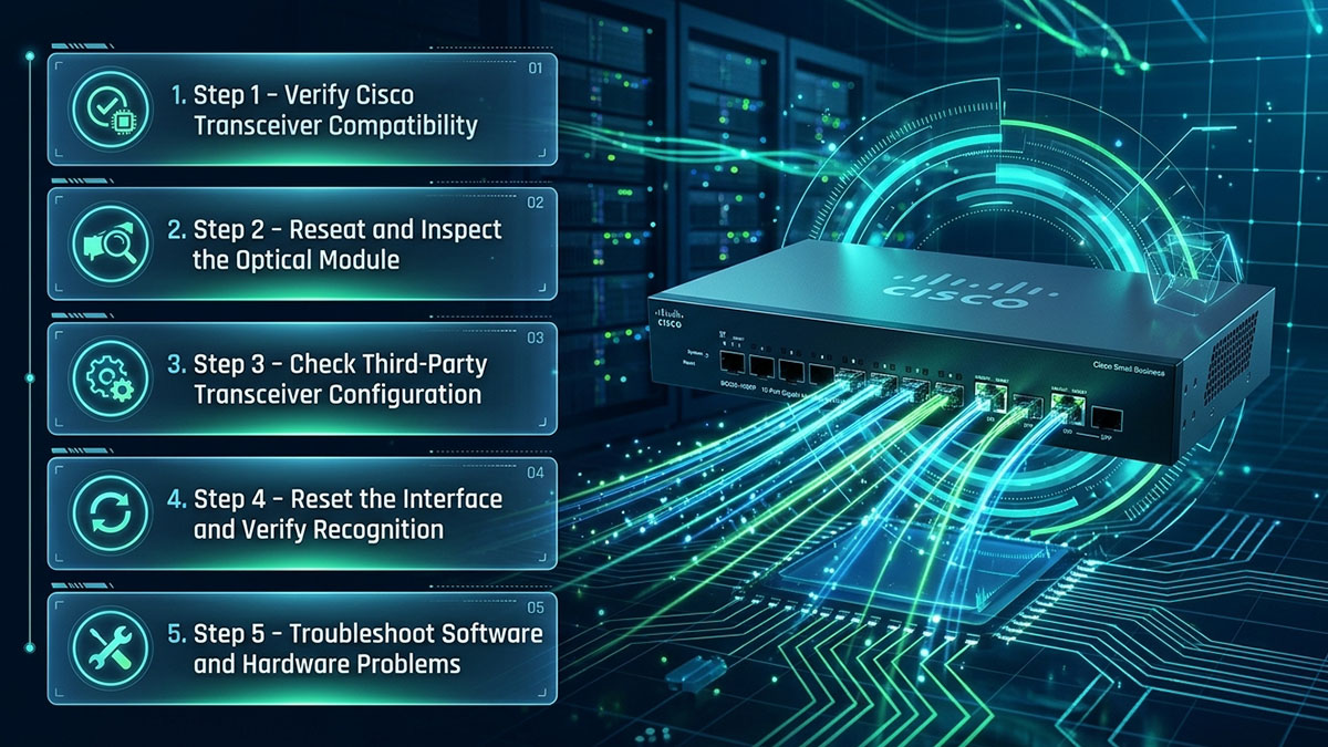
The following procedure is particularly useful for Cisco Catalyst switches, although individual commands and configuration options must be checked against the exact platform.
Step 1 – Verify Cisco Transceiver Compatibility
Before modifying the switch configuration, confirm that the installed module is appropriate for the target Cisco device.
Collect the following information:
-
Complete Cisco switch model and hardware revision.
-
IOS/IOS XE version.
-
Interface number and port type.
-
Transceiver part number and manufacturer.
-
Supported data rate and optical standard.
-
Wavelength and transmission distance.
-
Fiber type and connector.
Next, use the Cisco Optics-to-Device Compatibility Matrix to check the original Cisco-supported module combinations.
For third-party transceivers, also request confirmation of the specific switch model and port compatibility from the module manufacturer.
Do not rely on the general description "Cisco compatible." Compatibility with a Catalyst 9300, for example, does not automatically establish compatibility with a Catalyst 3850 or Nexus switch.
A proper compatibility check should establish both module recognition and optical interoperability.
Step 2 – Reseat and Inspect the Optical Module
If the module appears compatible, inspect the physical installation.
A poorly seated SFP can prevent the switch from reading its identification information correctly.
Follow these steps:
-
Follow the platform's approved module removal and insertion procedure.
-
Administratively shut down the affected interface if required by the maintenance procedure.
-
Remove the optical module carefully.
-
Inspect the module and SFP cage for visible damage.
-
Clean fiber connectors using approved optical cleaning tools.
-
Reinsert the module and ensure that it is fully seated.
-
Restore the interface if it was administratively disabled.
After reinsertion, check whether the switch recognizes the module.
Switch# show inventory
Switch# show interfaces status
Switch# show logging
If the module is now recognized, proceed to link verification.
If the same unsupported warning returns, continue with the configuration and compatibility investigation.
Step 3 – Check Third-Party Transceiver Configuration
Some Cisco platforms provide configuration options for operating third-party optical modules.
On supported Catalyst 3850 configurations, Cisco documents the following commands:
Switch# configure terminal
Switch(config)# no errdisable detect cause gbic-invalid
Switch(config)# service unsupported-transceiver
Switch(config)# end
These commands have different purposes:
-
no errdisable detect cause gbic-invaliddisables error-disabled detection for the specified invalid GBIC/SFP condition. -
service unsupported-transceiverenables unsupported transceiver operation on platforms that implement this feature.
Important: These commands are not universal Cisco commands. Their availability and behavior depend on the hardware platform and software release. Do not assume they apply to every Catalyst, Nexus, or IOS XE switch.
Disabling gbic-invalid detection also changes how the switch handles that error condition. It does not establish that an incompatible module is safe, supported, or capable of operating correctly.
Before applying these commands:
-
Confirm that the platform supports the configuration.
-
Review Cisco documentation for the exact software release.
-
Check organizational support and security policies.
-
Record the original configuration.
-
Follow the approved network change procedure.
Cisco specifically documents this configuration approach for certain Catalyst 3850 SFP compatibility scenarios.
Step 4 – Reset the Interface and Verify Recognition
After making an approved configuration change, reset the affected interface if required.
For example:
Switch# configure terminal
Switch(config)# interface GigabitEthernet1/0/1
Switch(config-if)# shutdown
Switch(config-if)# no shutdown
Switch(config-if)# end
The interface reset forces the port to reinitialize its operational state. It does not independently resolve an unsupported module or incorrect optical specification.
After the reset, verify the following:
-
The transceiver appears in the switch inventory.
-
The unsupported transceiver message no longer appears.
-
The interface is not in an err-disabled state.
-
The port transitions to an operational state.
-
Optical diagnostic readings are available where supported.
-
The remote endpoint establishes a compatible link.
Useful verification commands include:
Switch# show interfaces status
Switch# show interfaces GigabitEthernet1/0/1
Switch# show logging
Switch# show interfaces transceiver detail
If the interface remains down, check the remote module, fiber polarity, optical power, and port configuration.
Step 5 – Troubleshoot Software and Hardware Problems
If the unsupported transceiver error persists after compatibility and physical checks, investigate possible software and hardware problems.
A useful troubleshooting sequence is:
-
Check Cisco release notes for the exact switch model and software version.
-
Search for documented SFP recognition or OIR-related software defects.
-
Compare the behavior with another known-compatible transceiver.
-
Test the original module in another known-compatible port.
-
Inspect the affected SFP cage and hardware module.
-
Collect system logs and diagnostic output for further investigation.
The results can help narrow down the problem:
|
Test result |
Likely area of investigation |
|---|---|
|
Original module fails in multiple compatible ports |
Module configuration or module hardware |
|
Multiple compatible modules fail in one port |
Switch port or SFP cage |
|
Module works after a software correction |
Software-related recognition problem |
|
Module is detected but no link forms |
Optical interface, fiber, or remote-end configuration |
|
Module works on another switch but not the target Cisco switch |
Platform-specific compatibility |
Do not repeatedly replace optical modules without comparing test results. A controlled one-component-at-a-time test is generally more effective.
Once the module is recognized and the interface is operational, monitor link stability and optical diagnostics to confirm that the issue has been resolved.
How to Prevent Unsupported Transceiver Errors When Using Third-Party Cisco-Compatible Modules
Preventing Cisco unsupported transceiver errors starts with verifying compatibility before installation. Network administrators should evaluate the switch model, port specifications, module identification, and optical interface rather than selecting a transceiver based only on its form factor or data rate.
A standardized pre-deployment verification process can reduce module recognition problems, unexpected interface shutdowns, and unnecessary network maintenance.
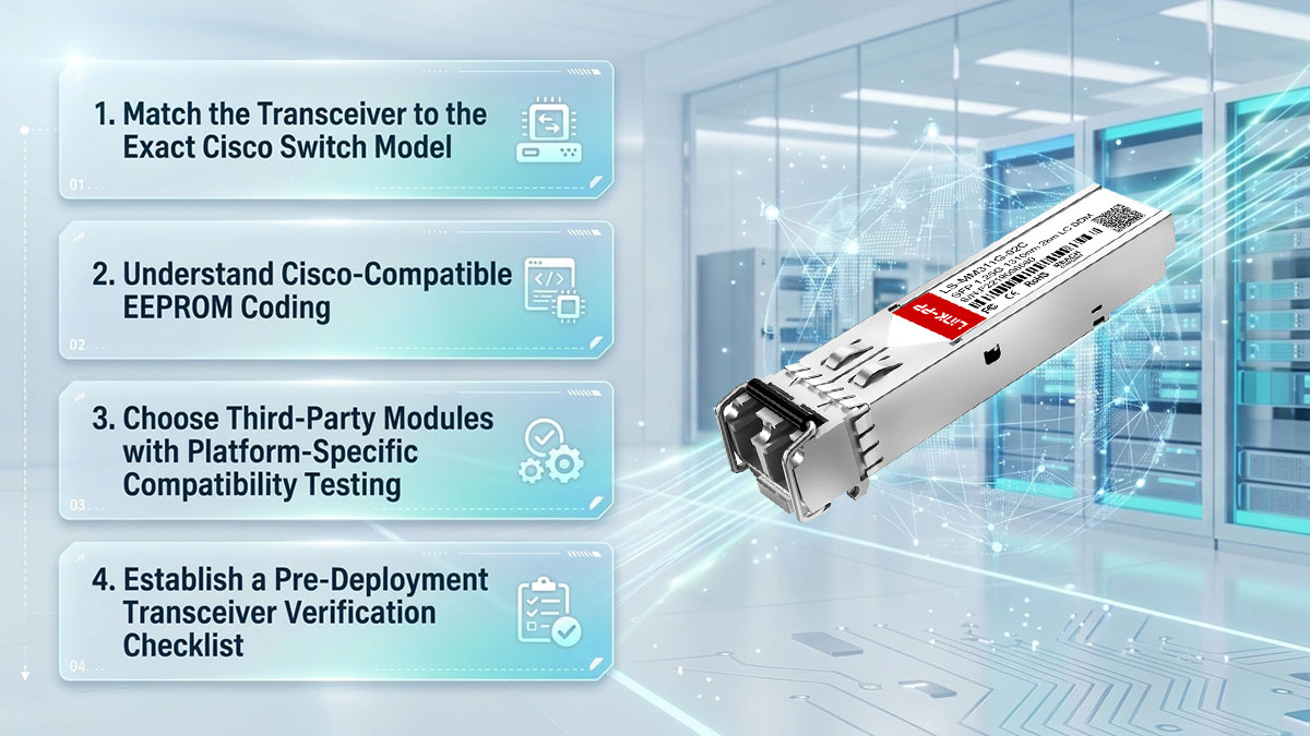
Match the Transceiver to the Exact Cisco Switch Model
The first preventive measure is to identify the exact Cisco switch and port configuration before selecting an optical module.
Even within the same Cisco product family, different models and hardware revisions may support different transceiver combinations.
Check the following information:
-
Switch model: Identify the complete product ID, such as Catalyst 9200, Catalyst 9300, Catalyst 3850, or Nexus 9000.
-
Port type: Determine whether the port supports SFP, SFP+, SFP28, QSFP+, or QSFP28 modules.
-
Operating speed: Confirm supported 1G, 10G, 25G, 40G, or 100G modes.
-
Optical standard: Verify the required standard, such as 1000BASE-SX, 10GBASE-SR, or 100GBASE-LR4.
-
Wavelength: Match the optical wavelength or wavelength combination at both ends.
-
Fiber type: Determine whether the connection requires single-mode or multimode fiber.
-
Software version: Check whether the intended transceiver and port mode are supported by the installed software.
The following table summarizes common LINK-PP-compatible module categories that may be considered for Cisco network environments. These are representative interface families, not a universal compatibility list.
|
Module category |
Data rate |
Common optical standards |
Typical application |
|---|---|---|---|
|
SFP |
1G |
1000BASE-SX, 1000BASE-LX/LH |
Enterprise access and aggregation |
|
SFP+ |
10G |
10GBASE-SR, 10GBASE-LR |
Data center and enterprise uplinks |
|
SFP28 |
25G |
25GBASE-SR, 25GBASE-LR |
High-density server connectivity |
|
QSFP+ |
40G |
40GBASE-SR4, 40GBASE-LR4 |
Data center aggregation |
|
QSFP28 |
100G |
100GBASE-SR4, 100GBASE-LR4 |
High-speed switching and spine links |
The exact supported reach, wavelength, connector, and fiber requirements depend on the individual transceiver specification. For example, 40GBASE-SR4 and 40GBASE-LR4 use different optical interfaces and cabling arrangements.
Therefore, matching the data rate alone is insufficient. Always verify the complete module datasheet and target switch compatibility.
Understand Cisco-Compatible EEPROM Coding
EEPROM coding is another important consideration when deploying third-party optical transceivers on Cisco switches.
A compatible module may require vendor-specific identification data so that the target switch can recognize its intended configuration.
Important considerations include:
-
Vendor identification: The module must present identification information appropriate for the intended host platform.
-
Part number configuration: The module should correspond to the specified optical interface and product configuration.
-
Management information: Available diagnostic and identification data should be correctly implemented.
-
Host recognition: The target Cisco switch should recognize the module under its applicable compatibility rules.
-
Optical interoperability: The module must still meet the electrical and optical requirements of the connection.
It is important to distinguish between EEPROM coding and optical performance.
Correct coding can help a Cisco switch recognize a third-party module, but it cannot compensate for an incorrect wavelength, incompatible data rate, insufficient optical power, or unsuitable fiber connection.
For this reason, both module recognition and physical link validation should be included in the deployment process.
Choose Third-Party Modules with Platform-Specific Compatibility Testing
Selecting a third-party optical module with documented platform-specific testing can reduce compatibility uncertainty.
Instead of relying only on a general compatibility statement, ask the manufacturer whether the module has been configured and validated for the exact Cisco switch family and interface.
Useful validation areas include:
-
Module recognition: Whether the switch correctly identifies the transceiver.
-
Link establishment: Whether the interface successfully establishes a connection.
-
Traffic transmission: Whether the link can carry traffic under the intended operating conditions.
-
DOM/DDM reporting: Whether supported diagnostic information is available.
-
Operational stability: Whether the connection remains stable during sustained operation.
For example, LINK-PP provides vendor-specific EEPROM programming and platform validation covering module recognition, link establishment, traffic transmission, and diagnostic reporting. Its compatibility information identifies supported platform categories, including Cisco.
However, administrators should still verify the exact switch model, software version, and port configuration. Testing on one Cisco platform does not automatically establish compatibility with every Cisco switch.
Establish a Pre-Deployment Transceiver Verification Checklist
A documented verification checklist helps prevent unsupported transceiver errors from appearing during production deployment.
Before installing a third-party optical module, confirm the following:
This checklist can also become part of the organization's optical module inventory and change-management process.
Keeping records of verified switch and transceiver combinations makes future replacements and network expansion easier to manage.
LINK-PP Cisco-Compatible Optical Transceivers: An Alternative to Consider
LINK-PP provides third-party compatible optical transceivers for network equipment from multiple manufacturers, including Cisco. Its product portfolio covers different form factors, data rates, and optical interfaces for enterprise networks, data centers, and telecommunications infrastructure.
For network administrators troubleshooting Cisco unsupported transceiver errors, LINK-PP modules are an alternative worth evaluating when the original module is unavailable, compatibility requirements need to be reviewed, or a third-party optical solution is being considered.
The most important selection criteria remain exact platform compatibility, appropriate EEPROM configuration, optical specifications, and validation under the intended operating conditions.
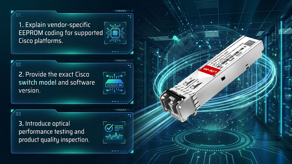
How LINK-PP Optical Modules Address Cisco Compatibility Requirements
LINK-PP's Cisco-compatible optical modules are configured with platform-specific identification information to support recognition by intended Cisco equipment.
The compatibility process involves several technical considerations:
1. Vendor-specific EEPROM programming
-
Configures identification information for the intended host platform.
-
Supports appropriate module identification and management data.
-
Helps the switch recognize the transceiver under applicable platform requirements.
2. Platform compatibility verification
-
Evaluates the intended Cisco switch and interface configuration.
-
Checks module recognition and link establishment.
-
Considers diagnostic reporting where supported.
3. Optical and operational validation
-
Checks optical performance against product specifications.
-
Evaluates link stability and traffic transmission.
-
Reviews diagnostic readings and relevant operating conditions.
According to LINK-PP's published quality and compatibility information, its modules undergo platform validation involving link establishment, sustained traffic, and diagnostic reporting.
These processes provide useful compatibility evidence, but the final module selection should always be based on the exact target Cisco device and deployment requirements.
Common LINK-PP Optical Transceiver Options for Cisco Switches
LINK-PP offers optical transceivers covering 1G to 400G applications, including SFP, SFP+, SFP28, QSFP+, QSFP28, and higher-speed module families.
The following are common optical module categories that network administrators may encounter when planning Cisco network connectivity.
1G SFP Optical Transceivers
-
1000BASE-SX
-
1000BASE-LX/LH
-
Commonly used for enterprise access switches and Gigabit Ethernet uplinks.
10G SFP+ Optical Transceivers
-
10GBASE-SR
-
10GBASE-LR
-
Suitable for 10G Ethernet connections in data centers and enterprise networks.
25G SFP28 Optical Transceivers
-
25GBASE-SR
-
25GBASE-LR
-
Used for high-density server connections and 25G switch uplinks.
40G QSFP+ Optical Transceivers
-
40GBASE-SR4
-
40GBASE-LR4
-
Used for data center aggregation and high-speed switching.
100G QSFP28 Optical Transceivers
-
100GBASE-SR4
-
100GBASE-LR4
-
Designed for high-bandwidth data center and backbone connections.
These categories represent different optical interfaces, not interchangeable modules. For instance, 40GBASE-SR4 uses parallel multimode optics, while 40GBASE-LR4 uses a wavelength-multiplexed single-mode interface.
Similarly, 100GBASE-SR4 and 100GBASE-LR4 differ in fiber type, connector configuration, and optical transmission characteristics.
The correct LINK-PP part number must therefore be selected according to the required Cisco port, optical standard, fiber infrastructure, and transmission distance.
How to Verify LINK-PP Module Compatibility Before Deployment
Before installing a LINK-PP optical module in a Cisco switch, provide the manufacturer with the actual equipment and connectivity requirements.
This makes it easier to identify the appropriate module configuration and avoid relying on generic compatibility descriptions.
Follow these steps:
Step 1: Identify the Cisco switch.
Record the complete switch model, hardware revision, and IOS/IOS XE version.
Step 2: Identify the original optical module or required interface.
Provide the original Cisco part number if available. Otherwise, specify the data rate, optical standard, wavelength, reach, and connector.
Step 3: Confirm Cisco-specific coding.
Verify that the proposed LINK-PP module is configured for the intended Cisco platform.
Step 4: Review compatibility information.
Request available information covering module recognition, supported interfaces, and relevant platform validation.
Step 5: Test the module in the intended environment.
Verify module identification, interface status, DOM/DDM readings where supported, and actual link performance.
A practical way to streamline this process is to use the LINK-PP compatibility tool or contact its technical team with the original transceiver part number and switch model.
LINK-PP Quality Control and Technical Support
Besides compatibility, product quality and technical support are important considerations when selecting third-party optical transceivers.
LINK-PP publishes information about its quality management and product validation processes through its Quality & Compliance Center.
Relevant areas include:
-
Optical performance testing: Evaluation of transmit power, receiver sensitivity, and other optical characteristics.
-
Environmental testing: Evaluation under specified operating conditions, including temperature and environmental stress.
-
Compatibility validation: Verification of module recognition, link establishment, and diagnostic reporting on intended platforms.
-
Product identification: Traceability through product and serial number information.
-
Technical assistance: Support for identifying suitable optical modules based on specific host equipment and connectivity requirements.
For network administrators, these details help establish whether a proposed optical module meets the technical requirements of the intended Cisco deployment.
You can review the LINK-PP Quality & Compliance Center for additional information about quality and compatibility verification.
Conclusion
The Cisco "Unsupported Transceiver" error does not necessarily indicate a defective optical module. In many cases, the problem is associated with Cisco transceiver compatibility restrictions, EEPROM identification, IOS/IOS XE software behavior, or incorrect module specifications.
Resolving the issue requires identifying the actual cause before replacing hardware or changing switch configurations.
The most important troubleshooting points include:
-
Identify the error: Examine Cisco system logs and distinguish unsupported module warnings from physical link failures.
-
Verify compatibility: Check the exact switch model, port type, software version, and optical specifications.
-
Use CLI diagnostics: Run
show inventory,show interfaces status, andshow loggingto collect evidence. -
Check configuration: Apply third-party transceiver settings only when supported by the target platform.
-
Validate the optical link: Confirm module recognition, fiber compatibility, optical power, and link stability.
-
Evaluate third-party alternatives: Consider LINK-PP Cisco-compatible optical modules with appropriate EEPROM configuration and platform-specific validation.
For network administrators considering third-party optical modules, LINK-PP provides an alternative with compatibility assistance and product quality verification. Its standard-stock products include a 15-day no-reason return policy, while LINK-PP covers return shipping costs for products with confirmed quality issues.
To identify a suitable replacement for your Cisco switch, start with the LINK-PP Compatibility Tool. Enter your original Cisco transceiver part number to check compatible module options. You can then submit your requirements to the LINK-PP technical team to obtain a compatibility assessment and quotation.
Visit the LINK-PP Official Store to review optical transceiver specifications, explore Cisco-compatible SFP/SFP+/QSFP modules, and find an appropriate connectivity solution for your network deployment.