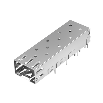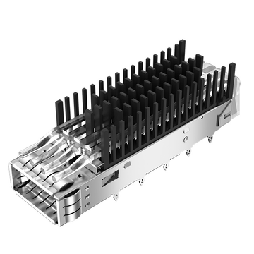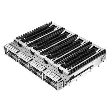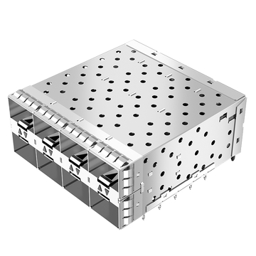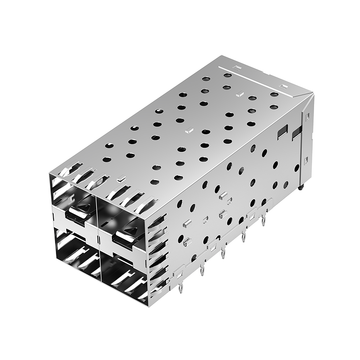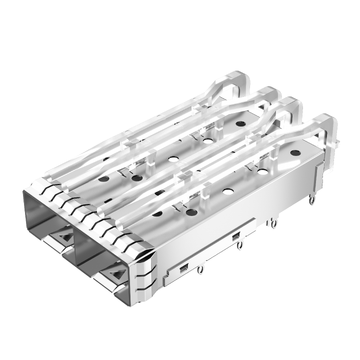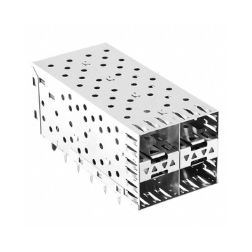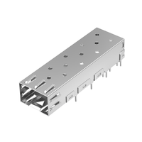
Τα clusters τεχνητής νοημοσύνης και τα δίκτυα edge 5G ωθούν την υποδομή δικτύου προς υψηλότερη πυκνότητα θυρών, ταχύτερους ρυθμούς δεδομένων και πιο απαιτητική συνδεσιμότητα στο μπροστινό πάνελ. Οι διακομιστές, οι διακόπτες και οι επιταχυντές τεχνητής νοημοσύνης βασίζονται όλο και περισσότερο σε οπτικές διεπαφές υψηλής ταχύτητας, ενώ οι αρχιτεκτονικές front-haul 5G απαιτούν συμπαγείς και αξιόπιστες συνδέσεις μεταξύ εξοπλισμού ραδιοεπικοινωνίας και edge computing. Σε αυτά τα περιβάλλοντα, ο οπτικός πομποδέκτης είναι μόνο ένα μέρος της φυσικής διεπαφής. Το κλουβί SFP/QSFP που στεγάζει και ασφαλίζει τη μονάδα συμβάλλει επίσης στη μηχανική σταθερότητα, την ευθυγράμμιση των συνδέσμων, την θωράκιση EMI, τη ροή αέρα και τη μακροπρόθεσμη λειτουργικότητα.
Αυτό καθιστά το κλουβί SFP/QSFP κάτι περισσότερο από ένα απλό εξάρτημα τοποθέτησης. LINK-PP Καθώς οι λύσεις κλωβού SFP/QSFP ενσωματώνονται σε πλατφόρμες δικτύωσης υψηλής πυκνότητας, οι μηχανικοί πρέπει να λάβουν υπόψη τον τρόπο με τον οποίο η κατασκευή του κλωβού αλληλεπιδρά με την εγκατάσταση του πομποδέκτη, τη γείωση του συστήματος, τις θερμικές συνθήκες και τις ηλεκτρικές διεπαφές υψηλής ταχύτητας. Η σωστή αρχιτεκτονική κλωβού μπορεί να βοηθήσει στη δημιουργία ενός πιο σταθερού περιβάλλοντος διεπαφής για απαιτητικές αναπτύξεις συμπλεγμάτων τεχνητής νοημοσύνης και 5G σε front-haul περιβάλλοντα.
Αυτό το άρθρο εξετάζει γιατί οι κλωβοί SFP/QSFP είναι κρίσιμοι σε αυτές τις εφαρμογές, εστιάζοντας στα εξής:
- Πώς ο σχεδιασμός του κλωβού υποστηρίζει τη συνδεσιμότητα υψηλής ταχύτητας στο μπροστινό πάνελ
- Γιατί οι συστάδες τεχνητής νοημοσύνης δημιουργούν μεγαλύτερες μηχανικές, θερμικές και πυκνοτικές απαιτήσεις
- Πώς οι εφαρμογές 5G σε front-haul περιοχές επηρεάζουν τον σχεδιασμό και τη λειτουργικότητα των κλουβιών
- Ποιους μηχανικούς, ηλεκτρομαγνητικούς, θερμικούς και ακεραιότητας σήματος παράγοντες θα πρέπει να αξιολογήσουν οι μηχανικοί;
- Πώς να επιλέξετε και να επικυρώσετε LINK-PP Λύσεις κλωβού SFP/QSFP για εφαρμογές σε πραγματικό κόσμο
Μαζί, αυτές οι σκέψεις παρέχουν ένα πρακτικό πλαίσιο για την αξιολόγηση των κλωβών SFP/QSFP ως μέρος της πλήρους αρχιτεκτονικής συνδεσιμότητας και όχι ως ένα μεμονωμένο μηχανικό στοιχείο.
🥏 Πώς υποστηρίζει ένα κλουβί SFP/QSFP συνδεσιμότητα υψηλής ταχύτητας στον μπροστινό πίνακα;
Ένα κλουβί SFP/QSFP υποστηρίζει συνδεσιμότητα υψηλής ταχύτητας στο μπροστινό πάνελ παρέχοντας μια μηχανικά ακριβή διεπαφή που τοποθετεί, διατηρεί, προστατεύει και εξυπηρετεί τον οπτικό πομποδέκτη. Παρόλο που το κλουβί δεν παράγει ούτε επεξεργάζεται το οπτικό σήμα, η γεωμετρία, η τοποθέτηση, η γείωση και η δομική του σταθερότητα επηρεάζουν την αξιοπιστία της διασύνδεσης του πομποδέκτη με την υποδοχή υποδοχής και το περιβάλλον σύστημα. Αυτό αποκτά ολοένα και μεγαλύτερη σημασία σε διακόπτες τεχνητής νοημοσύνης υψηλής πυκνότητας, διακομιστές και πλατφόρμες 5G edge, όπου πολλές θύρες υψηλής ταχύτητας λειτουργούν σε περιορισμένο φυσικό χώρο.
Το κλουβί ως μηχανική διεπαφή για οπτικούς πομποδέκτες
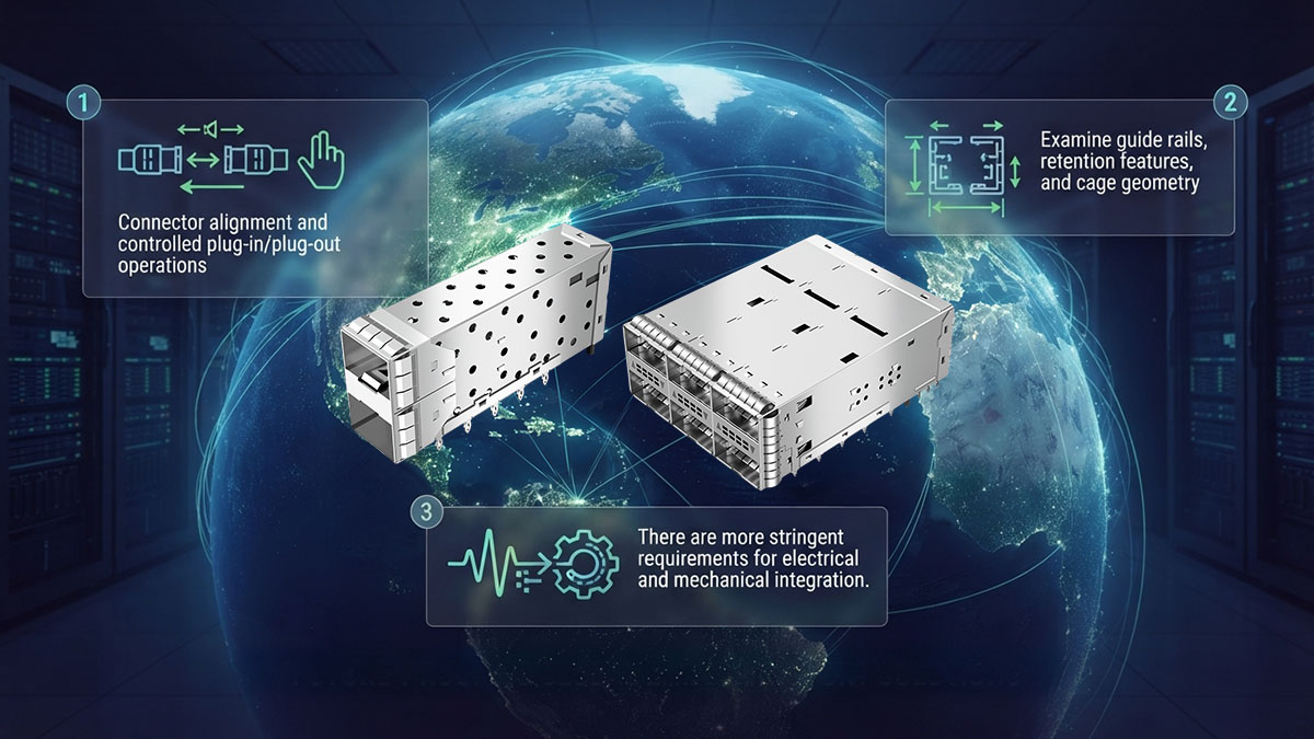
Το κλουβί SFP/QSFP παρέχει τη φυσική υποδοχή που οδηγεί τον πομποδέκτη στην υποδοχή υποδοχής και τον διατηρεί σταθερά τοποθετημένο κατά τη λειτουργία. Αυτή η βασική λειτουργία καθίσταται κρίσιμη όταν ο εξοπλισμός περιέχει δεκάδες οπτικές θύρες σε κοντινή απόσταση μεταξύ τους.
Ένα σωστά σχεδιασμένο κλουβί συνήθως υποστηρίζει αρκετές μηχανικές απαιτήσεις:
- Οδηγίες πομποδέκτη: Η γεωμετρία του εσωτερικού κλωβού βοηθά στην καθοδήγηση της μονάδας προς τον ηλεκτρικό σύνδεσμο κατά την εισαγωγή.
- Διατήρηση ενότητας: Τα χαρακτηριστικά συγκράτησης βοηθούν στην αποτροπή ακούσιας κίνησης ή μερικής αποσύνδεσης μετά την εγκατάσταση.
- Ευθυγράμμιση συνδετήρα: Η συνεπής τοποθέτηση βοηθά στη διατήρηση της σωστής εμπλοκής μεταξύ του πομποδέκτη και της υποδοχής κεντρικού υπολογιστή.
- Ενσωμάτωση μπροστινού πίνακα: Ο κλωβός πρέπει να ταιριάζει στην πλακέτα τυπωμένου κυκλώματος, το πλαίσιο, το πλαίσιο και τα γειτονικά κλωβά χωρίς να δημιουργεί μηχανικές παρεμβολές.
- Πρόσβαση στην υπηρεσία: Η διάταξη θα πρέπει να επιτρέπει στους τεχνικούς να εισάγουν και να αφαιρούν μονάδες χωρίς υπερβολική δύναμη ή παρεμβολές από γειτονικές θύρες.
Αυτές οι λειτουργίες είναι ιδιαίτερα σχετικές με τις διεπαφές SFP+, SFP28, QSFP28 και νεότερες υψηλής πυκνότητας, επειδή οι μικρές μηχανικές αποκλίσεις μπορεί να γίνουν πιο δύσκολες στη διαχείριση καθώς μειώνεται η απόσταση μεταξύ των θυρών. Επομένως, ο κλωβός χρησιμεύει ως η μηχανική βάση γύρω από την οποία συναρμολογείται η πλήρης διεπαφή του πομποδέκτη.
Πώς η δομή του κλωβού επηρεάζει την ευθυγράμμιση και τη συγκράτηση του πομποδέκτη
Η δομή του κλωβού επηρεάζει τη συνδεσιμότητα κυρίως διατηρώντας μια σταθερή μηχανική σχέση μεταξύ του πομποδέκτη, του συνδέσμου κεντρικού υπολογιστή, της πλακέτας τυπωμένου κυκλώματος (PCB) και του μπροστινού πίνακα. Η σωστή ευθυγράμμιση βοηθά τη μονάδα να εμπλέκεται σταθερά, μειώνοντας παράλληλα τη μηχανική καταπόνηση του συνδέσμου κατά την εγκατάσταση και την αφαίρεση.
Οι μηχανικοί θα πρέπει να αξιολογούν τα ακόλουθα χαρακτηριστικά του κλωβού κατά την αξιολόγηση της μηχανικής ολοκλήρωσης:
- Διαστατική ανοχή: Οι σταθερές διαστάσεις βοηθούν στη διατήρηση της προβλέψιμης τοποθέτησης του πομποδέκτη σε πολλαπλές θύρες.
- Γεωμετρία οδηγού: Οι σωστά τοποθετημένοι οδηγοί μπορούν να μειώσουν την κακή ευθυγράμμιση κατά την εισαγωγή.
- Δομή διατήρησης: Ένας σταθερός μηχανισμός συγκράτησης βοηθά στη διατήρηση της μονάδας στη θέση της κατά τη διάρκεια της κανονικής λειτουργίας.
- Σταθερότητα τοποθέτησης: Η ασφαλής σύνδεση της πλακέτας τυπωμένου κυκλώματος βοηθά στην αποτροπή της μετακίνησης του κλωβού σε σχέση με την υποδοχή κεντρικού υπολογιστή.
- Άδεια παρακείμενου λιμένα: Η επαρκής απόσταση μειώνει τις παρεμβολές όταν εγκαθίστανται ή αφαιρούνται γειτονικοί πομποδέκτες.
Η σημασία αυτών των χαρακτηριστικών αυξάνεται στον εξοπλισμό cluster AI και στον εξοπλισμό edge 5G, επειδή η συντήρηση μπορεί να περιλαμβάνει επαναλαμβανόμενο χειρισμό μονάδων. Ένας κλωβός που διατηρεί την ευθυγράμμιση και τη διατήρηση σε επαναλαμβανόμενους κύκλους σέρβις μπορεί να βοηθήσει στη διατήρηση συνεπούς φυσικής συνδεσιμότητας καθ' όλη τη διάρκεια λειτουργίας της πλατφόρμας.
Γιατί το Cage γίνεται πιο σημαντικό σε υψηλότερες ταχύτητες θύρας
Καθώς αυξάνονται οι ταχύτητες του δικτύου, ο κλωβός SFP/QSFP πρέπει να θεωρείται ως μέρος μιας πιο στενά ενσωματωμένης διεπαφής κεντρικού υπολογιστή. Οι πλατφόρμες υψηλότερης ταχύτητας έχουν μικρότερη ανοχή σε κακώς συντονισμένο μηχανικό, ηλεκτρικό, θερμικό σχεδιασμό και σχεδιασμό γείωσης, παρόλο που ο ίδιος ο κλωβός δεν είναι ο κύριος καθοριστικός παράγοντας για την απόδοση του σήματος.
Οι βασικές σχέσεις σε επίπεδο συστήματος περιλαμβάνουν:
- Τοποθέτηση κλωβού και δρομολόγηση πλακέτας τυπωμένου κυκλώματος: Η φυσική θέση του κλωβού και της υποδοχής κεντρικού υπολογιστή επηρεάζει τον τρόπο με τον οποίο δρομολογούνται οι ιχνηλασίες υψηλής ταχύτητας μεταξύ της υποδοχής και άλλων στοιχείων του συστήματος.
- Γείωση και θωράκιση: Το κλουβί μπορεί να συμβάλει στο αγώγιμο περιβάλλον που περιβάλλει τη διεπαφή του πομποδέκτη και να βοηθήσει στην υποστήριξη του ελέγχου EMI σε επίπεδο συστήματος.
- Σταθερότητα συνδετήρα: Η μηχανική κίνηση ή η ασυνεπής τοποθέτηση μπορεί να ασκήσει πρόσθετη πίεση στην ηλεκτρική διεπαφή.
- Πυκνότητα λιμένα: Τα κλουβιά σε κοντινή απόσταση απαιτούν προσεκτικό συντονισμό μεταξύ μηχανικών διαστάσεων, δρομολόγησης σήματος, θερμικής διαχείρισης και πρόσβασης σε υπηρεσίες.
- Ενσωμάτωση πομποδέκτη: Ο κλωβός, ο σύνδεσμος, η πλακέτα τυπωμένου κυκλώματος, το πλαίσιο και η οπτική μονάδα θα πρέπει να επικυρώνονται ως μία διεπαφή και όχι να αξιολογούνται ανεξάρτητα.
Για παράδειγμα, μια πλατφόρμα 400G που βασίζεται σε QSFP μπορεί να απαιτεί σημαντικά πιο προσεκτική μηχανική και ηλεκτρική ενσωμάτωση από μια πλατφόρμα χαμηλότερης ταχύτητας, επειδή πολλαπλές ηλεκτρικές λωρίδες υψηλής ταχύτητας συγκεντρώνονται σε μια συμπαγή διεπαφή. Κατά συνέπεια, η επιλογή ενός κλωβού SFP/QSFP θα πρέπει να περιλαμβάνει περισσότερα από την επιβεβαίωση ότι ο ονομαστικός συντελεστής μορφής του πομποδέκτη ταιριάζει. Οι μηχανικοί θα πρέπει να επαληθεύσουν τη συμβατότητα του κλωβού με την πλήρη αρχιτεκτονική του κεντρικού υπολογιστή.
🥏 Γιατί είναι σημαντικοί οι κλωβοί SFP/QSFP στη συνδεσιμότητα συμπλεγμάτων τεχνητής νοημοσύνης;
Τα κλουβιά SFP/QSFP είναι σημαντικά στη συνδεσιμότητα συμπλεγμάτων τεχνητής νοημοσύνης (AI cluster), επειδή παρέχουν τη μηχανική και φυσική διεπαφή που απαιτείται για την αξιόπιστη ανάπτυξη μεγάλου αριθμού πομποδεκτών υψηλής ταχύτητας σε διακομιστές, διακόπτες και δίκτυα επιταχυντών. Τα συμπλέγματα τεχνητής νοημοσύνης εξαρτώνται από συνδέσεις υψηλού εύρους ζώνης μεταξύ υπολογιστικών κόμβων, GPU, διακόπτων και συστημάτων αποθήκευσης, καθιστώντας την πυκνότητα θυρών του μπροστινού πίνακα, τη σταθερότητα του πομποδέκτη, τις θερμικές συνθήκες και τη λειτουργικότητα ολοένα και πιο σημαντική. Επομένως, το κλουβί αποτελεί μέρος της υποδομής που επιτρέπει σε αυτές τις οπτικές διεπαφές υψηλής ταχύτητας να λειτουργούν με συνέπεια σε μεγάλη κλίμακα.
Τα δίκτυα συμπλεγμάτων τεχνητής νοημοσύνης απαιτούν υψηλή πυκνότητα θυρών
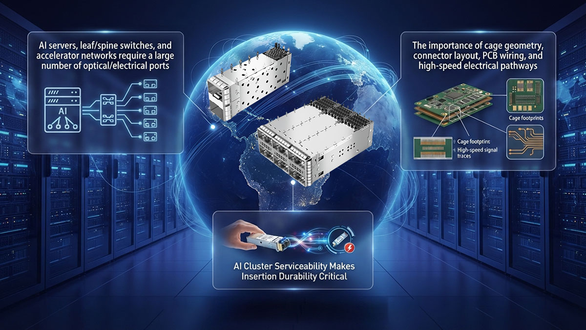
Τα δίκτυα συμπλεγμάτων τεχνητής νοημοσύνης απαιτούν μεγάλο αριθμό θυρών υψηλής ταχύτητας, επειδή τα κατανεμημένα φόρτα εργασίας υπολογισμού δημιουργούν σημαντική κίνηση ανατολικά-δυτικά μεταξύ διακομιστών και συσκευών δικτύου. Οι διαμορφώσεις κλωβού SFP/QSFP υψηλής πυκνότητας επιτρέπουν την ενσωμάτωση περισσότερων οπτικών διεπαφών σε περιορισμένο χώρο του μπροστινού πίνακα, διατηρώντας παράλληλα την πρόσβαση σε μεμονωμένες μονάδες πομποδέκτη.
Αρκετοί παράγοντες καθιστούν την πυκνότητα των κλουβιών ιδιαίτερα σημαντική στην υποδομή τεχνητής νοημοσύνης:
- Μεγάλος αριθμός συνδέσεων επιταχυντή: Τα συμπλέγματα GPU και επιταχυντών απαιτούν εκτεταμένη χωρητικότητα διασύνδεσης μεταξύ των υπολογιστικών κόμβων και των επιπέδων μεταγωγής.
- Διεπαφές διακόπτη υψηλής ταχύτητας: Τα σύγχρονα υφάσματα τεχνητής νοημοσύνης μπορούν να χρησιμοποιήσουν οπτικές θύρες υψηλής ταχύτητας για να συνδέσουν φύλλα, σπονδυλική στήλη και άλλα επίπεδα δικτύου.
- Περιορισμένος χώρος στο μπροστινό πάνελ: Η αύξηση του αριθμού των θυρών δημιουργεί μεγαλύτερους μηχανικούς περιορισμούς εντός ενός σταθερού πλάτους πλαισίου.
- Απαιτήσεις διαχείρισης καλωδίων: Οι πυκνές οπτικές διεπαφές πρέπει να αφήνουν επαρκή χώρο για τη δρομολόγηση των οπτικών ινών, την πρόσβαση στους συνδέσμους και τη συντήρηση.
- Αλληλεπίδραση γειτονικού λιμανιού: Οι διαστάσεις και η απόσταση μεταξύ των κλωβών πρέπει να αποτρέπουν την παρεμβολή μιας μονάδας ή καλωδίου σε μια άλλη.
Ως αποτέλεσμα, ένας διακόπτης AI δεν μπορεί να αξιολογηθεί μόνο από τον αριθμό των θυρών που καθορίζονται στο σχεδιασμό του. Η φυσική διάταξη του κλωβού πρέπει επίσης να προσαρμόζεται στις διαστάσεις του πομποδέκτη, την πρόσβαση στα καλώδια, τη ροή αέρα και τις λειτουργίες σέρβις. Μια καλά ενσωματωμένη διαμόρφωση κλωβού βοηθά στη μετατροπή της υψηλής πυκνότητας θυρών σε μια πρακτική ανάπτυξη αντί να μεγιστοποιεί απλώς τον αριθμό των διεπαφών στον πίνακα.
Οι συνδέσεις τεχνητής νοημοσύνης υψηλής ταχύτητας αυξάνουν την ευαισθησία ακεραιότητας σήματος
Οι συνδέσεις τεχνητής νοημοσύνης υψηλής ταχύτητας αυξάνουν τη σημασία της προσεκτικής ενσωμάτωσης σε κλουβί, επειδή οι υψηλότεροι ρυθμοί δεδομένων θέτουν μεγαλύτερες απαιτήσεις στην ηλεκτρική διεπαφή που συνδέει τον πομποδέκτη με το σύστημα υποδοχής. Ο ίδιος ο κλωβός δεν καθορίζει την ακεραιότητα του σήματος, αλλά η θέση του, η γείωση, η θωράκιση και η μηχανική σχέση του με τον σύνδεσμο και την πλακέτα τυπωμένου κυκλώματος αποτελούν μέρος του περιβάλλοντος διεπαφής υψηλής ταχύτητας.
Οι μηχανικοί θα πρέπει να λάβουν υπόψη διάφορους αλληλένδετους παράγοντες:
- Θέση σύνδεσης: Ο κλωβός και ο σύνδεσμος κεντρικού υπολογιστή πρέπει να διατηρούν σταθερή φυσική ευθυγράμμιση.
- Δρομολόγηση PCB: Η τοποθέτηση του κλωβού επηρεάζει τη διαθέσιμη διαδρομή δρομολόγησης μεταξύ των συνδέσμων υψηλής ταχύτητας και των στοιχείων του συστήματος.
- Γείωση: Ένα σωστά ενσωματωμένο αγώγιμο κλουβί μπορεί να υποστηρίξει την προβλεπόμενη αρχιτεκτονική γείωσης και θωράκισης.
- Ηλεκτρομαγνητικό περιβάλλον: Οι πυκνές θύρες υψηλής ταχύτητας απαιτούν προσεκτικό έλεγχο της ηλεκτρομαγνητικής σύζευξης γύρω από τη διεπαφή.
- Μηχανική σταθερότητα: Η συνεπής τοποθέτηση του πομποδέκτη βοηθά στην αποφυγή περιττής μηχανικής καταπόνησης στον κεντρικό σύνδεσμο.
Αυτές οι παράμετροι αποκτούν μεγαλύτερη σημασία καθώς οι πλατφόρμες Τεχνητής Νοημοσύνης κινούνται προς οπτικές διεπαφές υψηλότερης ταχύτητας και ολοένα και πιο πυκνές αρχιτεκτονικές μεταγωγής. Επομένως, η επιλογή κλωβού θα πρέπει να συντονίζεται με τη διάταξη της πλακέτας τυπωμένου κυκλώματος (PCB), την επιλογή σύνδεσης, τις προδιαγραφές του πομποδέκτη και την επικύρωση ακεραιότητας σήματος σε επίπεδο συστήματος και όχι να αντιμετωπίζεται ως μεμονωμένη μηχανική απόφαση.
Η δυνατότητα συντήρησης συμπλέγματος τεχνητής νοημοσύνης καθιστά κρίσιμη την ανθεκτικότητα της εισαγωγής
Η λειτουργικότητα του συμπλέγματος τεχνητής νοημοσύνης καθιστά σημαντική την ανθεκτικότητα του κύκλου εισαγωγής, επειδή η οπτική υποδομή υψηλής πυκνότητας μπορεί να απαιτεί την επιθεώρηση, αντικατάσταση, δοκιμή ή αναδιαμόρφωση μεμονωμένων πομποδεκτών χωρίς να τεθεί εκτός λειτουργίας ολόκληρος ο διακόπτης ή ο διακομιστής. Κάθε λειτουργία συντήρησης θέτει μηχανικές απαιτήσεις στον κλωβό, τη δομή συγκράτησης και τη διεπαφή του κεντρικού υπολογιστή.
Για τη μακροπρόθεσμη λειτουργία ενός συμπλέγματος τεχνητής νοημοσύνης, οι μηχανικοί θα πρέπει να δώσουν προσοχή στα εξής:
- Κύκλοι εισαγωγής και εξαγωγής: Ο κλωβός θα πρέπει να διατηρεί τα μηχανικά του χαρακτηριστικά κατά τον επαναλαμβανόμενο χειρισμό των μονάδων.
- Συνέπεια διατήρησης: Οι εγκατεστημένοι πομποδέκτες θα πρέπει να παραμένουν σταθερά τοποθετημένοι κατά τη διάρκεια της κανονικής λειτουργίας.
- Σταθερότητα ευθυγράμμισης: Η επαναλαμβανόμενη συντήρηση δεν θα πρέπει να προκαλεί σημαντική παραμόρφωση ή απώλεια ευθυγράμμισης.
- Προσβασιμότητα ενότητας: Οι πυκνές διατάξεις κλωβών θα πρέπει να επιτρέπουν στους τεχνικούς να έχουν πρόσβαση σε μεμονωμένους πομποδέκτες.
- Προβλεψιμότητα συντήρησης: Η συνεπής μηχανική συμπεριφορά σε όλες τις θύρες μπορεί να απλοποιήσει τις διαδικασίες αντικατάστασης και αντιμετώπισης προβλημάτων.
Αυτό καθιστά την ανθεκτικότητα εισαγωγής κάτι περισσότερο από μια απλή εργαστηριακή προδιαγραφή. Σε ένα μεγάλο σύμπλεγμα τεχνητής νοημοσύνης, η επαναλαμβανόμενη συντήρηση σε πολλές οπτικές θύρες μπορεί να μετατρέψει μικρές μηχανικές αδυναμίες σε επαναλαμβανόμενα λειτουργικά προβλήματα. Ένα ανθεκτικό κλουβί SFP/QSFP βοηθά στη διατήρηση μιας σταθερής φυσικής διεπαφής, υποστηρίζοντας παράλληλα τη λειτουργικότητα που απαιτείται από τα περιβάλλοντα δικτύωσης τεχνητής νοημοσύνης υψηλής πυκνότητας.
🥏 Πώς επηρεάζει ένα κλουβί SFP/QSFP τη συνδεσιμότητα 5G σε front-haul;
Ένας κλωβός SFP/QSFP επηρεάζει τη συνδεσιμότητα 5G σε front-haul, παρέχοντας μια σταθερή, λειτουργική και μηχανικά ελεγχόμενη διεπαφή για οπτικούς πομποδέκτες που χρησιμοποιούνται μεταξύ εξοπλισμού ραδιοεπικοινωνίας και δικτύου edge. Παρόλο που ο κλωβός δεν καθορίζει τα χαρακτηριστικά οπτικής μετάδοσης του πομποδέκτη, η μηχανική ευθυγράμμιση, η συγκράτηση, η πυκνότητα, η θερμική ενσωμάτωση και η θωράκιση μπορούν να επηρεάσουν την αξιοπιστία της φυσικής διεπαφής. Αυτό είναι ιδιαίτερα σημαντικό σε συστήματα front-haul 5G, όπου ο συμπαγής εξοπλισμός, οι κατανεμημένες αναπτύξεις και η υψηλή πυκνότητα θυρών μπορούν να αυξήσουν τις απαιτήσεις που επιβάλλονται στην οπτική συνδεσιμότητα.
Οπτικές διεπαφές κοντά στην άκρη του δικτύου σε τοποθεσίες front-haul
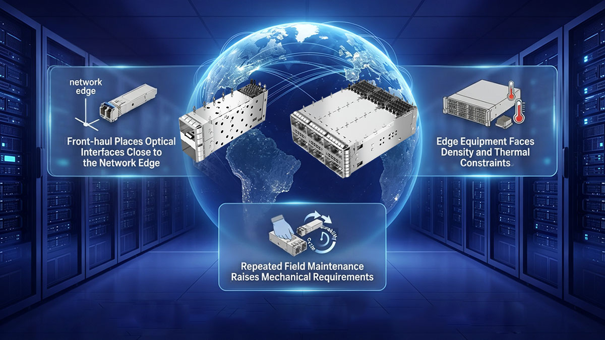
Το 5G front-haul τοποθετεί οπτικές διεπαφές απευθείας στη διαδρομή σύνδεσης μεταξύ Μονάδων Ραδιοεπικοινωνίας (RU) και Κατανεμημένων Μονάδων (DU), καθιστώντας τις συμπαγείς και αξιόπιστες διεπαφές πομποδέκτη σημαντικές για τη λειτουργία του δικτύου. Ανάλογα με την αρχιτεκτονική, οι οπτικές μονάδες παρέχουν τη φυσική σύνδεση που απαιτείται για τη μεταφορά κίνησης υψηλού εύρους ζώνης μεταξύ του ραδιοεπικοινωνιακού εξοπλισμού και του εξοπλισμού επεξεργασίας.
Ο ρόλος του κλωβού SFP/QSFP καθίσταται σημαντικός επειδή πρέπει να ενσωματώνει την οπτική διεπαφή στην πλατφόρμα υποδοχής διατηρώντας παράλληλα μηχανική και ηλεκτρική συνέπεια. Βασικές παράμετροι περιλαμβάνουν:
- Συνδεσιμότητα RU-προς-DU: Οι διεπαφές μπροστινής διαδρομής συνδέουν τον εξοπλισμό ραδιοεπικοινωνίας με την κατανεμημένη υποδομή επεξεργασίας.
- Μεταφορά υψηλού εύρους ζώνης: Η αύξηση της χωρητικότητας 5G μπορεί να απαιτήσει οπτικές διεπαφές υψηλότερης ταχύτητας και μεγαλύτερη πυκνότητα θυρών.
- Συμπαγής σχεδιασμός εξοπλισμού: Οι πλατφόρμες Edge και τηλεπικοινωνιών συχνά έχουν περιορισμένο φυσικό χώρο για οπτικές θύρες.
- Επιτόπια δυνατότητα συντήρησης: Ενδέχεται να χρειαστεί πρόσβαση σε μεμονωμένους πομποδέκτες χωρίς να αντικατασταθεί ολόκληρη η συσκευή δικτύου.
- Σταθερότητα διεπαφής: Ο κλωβός πρέπει να διατηρεί αξιόπιστη τοποθέτηση της μονάδας και εμπλοκή του συνδετήρα κατά τη λειτουργία.
Συνεπώς, ο κλωβός θα πρέπει να θεωρείται ως μέρος της φυσικής διεπαφής front-haul και όχι απλώς ως ένα εξάρτημα του περιβλήματος. Ο μηχανικός σχεδιασμός του πρέπει να λειτουργεί με τον πομποδέκτη, τον σύνδεσμο, την πλακέτα τυπωμένου κυκλώματος (PCB) και το πλαίσιο για να υποστηρίζει αξιόπιστη συνδεσιμότητα σε κατανεμημένη υποδομή 5G.
Πυκνότητα και Θερμικοί Περιορισμοί Επιφανειών Εξοπλισμού 5G Edge
Ο εξοπλισμός edge 5G αντιμετωπίζει περιορισμούς τόσο στην πυκνότητα των θυρών όσο και στους θερμικούς περιορισμούς, επειδή περισσότερες οπτικές διεπαφές μπορούν να συγκεντρωθούν σε σχετικά συμπαγείς πλατφόρμες. Καθώς αυξάνεται ο αριθμός των πομποδεκτών, η διάταξη του κλωβού πρέπει να παρέχει επαρκή χώρο για την εγκατάσταση της μονάδας, επιτρέποντας παράλληλα τη ροή του αέρα και διατηρώντας την πρόσβαση στις γειτονικές θύρες.
Αρκετοί παράγοντες που σχετίζονται με το κλουβί επηρεάζουν άμεσα αυτήν την ενσωμάτωση:
- Διαρρύθμιση λιμένα: Τα στοιβαγμένα ή σε κοντινή απόσταση μεταξύ τους κλουβιά μπορούν να αυξήσουν την πυκνότητα διεπαφής, αλλά απαιτούν προσεκτικό μηχανικό σχεδιασμό.
- Διάκενο ροής αέρα: Οι διατάξεις των κλωβών δεν πρέπει να εμποδίζουν άσκοπα τη ροή του αέρα γύρω από τους εγκατεστημένους πομποδέκτες.
- Παραγωγή θερμότητας μονάδας: Οι οπτικές μονάδες υψηλότερης ταχύτητας μπορούν να εισαγάγουν μεγαλύτερα θερμικά φορτία που πρέπει να ληφθούν υπόψη σε επίπεδο συστήματος.
- Γειτονικές ενότητες: Οι πομποδέκτες που βρίσκονται σε κοντινή απόσταση μπορούν να επηρεάσουν την τοπική συσσώρευση θερμότητας και την προσβασιμότητα στην υπηρεσία.
- Ενσωμάτωση πλαισίου: Οι διαστάσεις και η τοποθέτηση του κλωβού πρέπει να ταιριάζουν με το περίβλημα, το πλαίσιο, την πλακέτα τυπωμένου κυκλώματος και την θερμική αρχιτεκτονική.
Για αυτόν τον λόγο, ένας κλωβός SFP/QSFP δεν θα πρέπει να αξιολογείται μόνο από το εάν μια συγκεκριμένη μονάδα ταιριάζει φυσικά. Σε πλατφόρμες edge 5G, οι μηχανικοί θα πρέπει να λαμβάνουν υπόψη τον κλωβό σε συνδυασμό με την κατανάλωση ισχύος της μονάδας, την κατεύθυνση της ροής του αέρα, τους περιορισμούς του πλαισίου και την πυκνότητα των γειτονικών διεπαφών.
Η επαναλαμβανόμενη συντήρηση πεδίου αυξάνει τις μηχανικές απαιτήσεις
Η επαναλαμβανόμενη επιτόπια συντήρηση αυξάνει τις μηχανικές απαιτήσεις για έναν κλωβό SFP/QSFP, επειδή ο εξοπλισμός front-haul μπορεί να είναι κατανεμημένος σε πολλές τοποθεσίες δικτύου όπου οι οπτικές μονάδες πρέπει να συντηρούνται ξεχωριστά. Ένας κλωβός πρέπει επομένως να διατηρεί αξιόπιστη συγκράτηση και ευθυγράμμιση, ενώ παράλληλα υποστηρίζει επαναλαμβανόμενη εισαγωγή και εξαγωγή.
Σημαντικές μηχανικές παραμέτρους περιλαμβάνουν:
- Ανθεκτικότητα κύκλου εισαγωγής: Ο κλωβός θα πρέπει να αντέχει τον αναμενόμενο αριθμό κύκλων εγκατάστασης και αφαίρεσης του πομποδέκτη.
- Αξιοπιστία διατήρησης: Η μονάδα θα πρέπει να παραμείνει σταθερά τοποθετημένη μετά την εγκατάσταση και κατά τη διάρκεια της κανονικής λειτουργίας του εξοπλισμού.
- Συνέπεια ευθυγράμμισης: Η επαναλαμβανόμενη συντήρηση δεν θα πρέπει να θέτει σε σημαντικό κίνδυνο τη σχέση μεταξύ του κλωβού, του πομποδέκτη και της υποδοχής κεντρικού υπολογιστή.
- Προσβασιμότητα μπροστινού πίνακα: Οι τεχνικοί χρειάζονται επαρκή χώρο για να χειρίζονται τα μάνδαλα και τις γλωττίδες έλξης των μονάδων.
- Μηχανική ανθεκτικότητα: Η κατασκευή του κλωβού θα πρέπει να αντέχει στην παραμόρφωση που θα μπορούσε να δυσχεράνει την εγκατάσταση της επόμενης μονάδας.
Αυτές οι απαιτήσεις καθίστανται ιδιαίτερα σημαντικές όταν τα δίκτυα 5G επεκτείνονται από κεντρικές τοποθεσίες σε κατανεμημένα περιβάλλοντα άκρων. Ένας μηχανικά συνεπής κλωβός μπορεί να βοηθήσει στην απλοποίηση της αντικατάστασης μονάδων και στη μείωση των προβλημάτων φυσικής διεπαφής κατά τη διάρκεια της τακτικής συντήρησης, υποστηρίζοντας πιο προβλέψιμη συνδεσιμότητα front-haul καθ' όλη τη διάρκεια ζωής του εξοπλισμού.
🥏 Ποιους τεχνικούς παράγοντες πρέπει να αξιολογούν οι μηχανικοί σε ένα κλουβί SFP/QSFP;
Οι μηχανικοί θα πρέπει να αξιολογήσουν ένα κλουβί SFP/QSFP σε τέσσερις βασικούς τομείς: μηχανική συμβατότητα, θωράκιση και γείωση EMI, θερμική συμπεριφορά και ανθεκτικότητα εισαγωγής. Ένα κλουβί που ταιριάζει με τον ονομαστικό συντελεστή μορφής πομποδέκτη ενδέχεται να είναι ακατάλληλο για έναν διακόπτη cluster AI ή μια πλατφόρμα edge 5G, εάν οι διαστάσεις, η τοποθέτηση, η θωράκιση, η ροή αέρα ή η μηχανική του διάρκεια ζωής δεν ταιριάζουν με το σύστημα υποδοχής. Η πιο αξιόπιστη αξιολόγηση επομένως θεωρεί το κλουβί ως μέρος της πλήρους διεπαφής του πομποδέκτη.
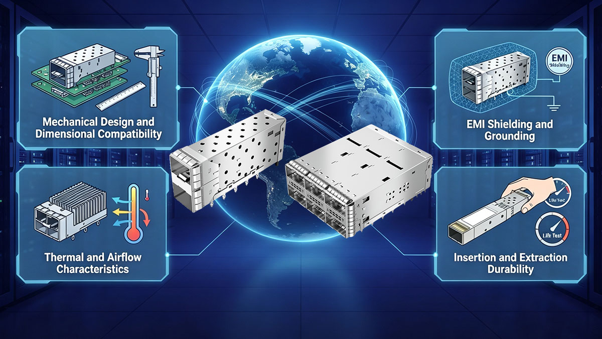
Μηχανικός Σχεδιασμός και Διαστατική Συμβατότητα
Η μηχανική συμβατότητα θα πρέπει να είναι το πρώτο σημείο αξιολόγησης, επειδή ο κλωβός πρέπει να ευθυγραμμίζεται σωστά με την πλακέτα τυπωμένου κυκλώματος (PCB), τον σύνδεσμο, το πλαίσιο και τον μπροστινό πίνακα. Μικρές διαφορές διαστάσεων μπορούν να επηρεάσουν την εισαγωγή της μονάδας, την εμπλοκή του συνδέσμου, την απόσταση μεταξύ των γειτονικών θυρών και τη συνολική δυνατότητα συντήρησης.
Οι μηχανικοί θα πρέπει να επαληθεύσουν τα ακόλουθα μηχανικά χαρακτηριστικά:
- Υποστηριζόμενος συντελεστής μορφής: Επιβεβαιώστε εάν ο κλωβός έχει σχεδιαστεί για τον απαιτούμενο πομποδέκτη οικογένειας SFP ή οικογένειας QSFP.
- Διαστάσεις κλουβιού: Ελέγξτε το συνολικό πλάτος, το ύψος, το βάθος και τις σχετικές μηχανικές ανοχές σε σχέση με την πλατφόρμα υποδοχής.
- Τοποθέτηση πλακέτας τυπωμένου κυκλώματος: Επαληθεύστε τη διαμόρφωση τοποθέτησης και τα σημεία μηχανικής σύνδεσης που απαιτούνται από την πλακέτα τυπωμένου κυκλώματος.
- Ευθυγράμμιση συνδετήρα: Βεβαιωθείτε ότι ο κλωβός τοποθετεί τον πομποδέκτη σωστά σε σχέση με τον ηλεκτρικό σύνδεσμο.
- Ενσωμάτωση μπροστινού πίνακα: Ελέγξτε τη συμβατότητα με το πλαίσιο, το άνοιγμα του πλαισίου και τα γύρω εξαρτήματα.
- Απόσταση θυρών: Βεβαιωθείτε ότι υπάρχει επαρκής απόσταση για γειτονικές μονάδες, μάνδαλα, γλωττίδες έλξης και καλώδια οπτικών ινών.
Αυτοί οι έλεγχοι είναι ιδιαίτερα σημαντικοί σε διακόπτες τεχνητής νοημοσύνης υψηλής πυκνότητας και εξοπλισμό edge 5G, όπου πολλά κλουβιά μπορούν να τοποθετηθούν κοντά το ένα στο άλλο. Συνεπώς, η μηχανική συμβατότητα θα πρέπει να επαληθεύεται τόσο σε επίπεδο μεμονωμένου κλωβού όσο και σε επίπεδο πλήρους συναρμολόγησης του μπροστινού πάνελ.
Θωράκιση και γείωση ηλεκτρομαγνητικών παρεμβολών (EMI)
Η θωράκιση και η γείωση έναντι ηλεκτρομαγνητικών παρεμβολών (EMI) θα πρέπει να αξιολογούνται, επειδή ο κλωβός αποτελεί μέρος του αγώγιμου περιβάλλοντος που περιβάλλει τον πομποδέκτη και τον σύνδεσμο του κεντρικού υπολογιστή. Ενώ ο κλωβός από μόνος του δεν μπορεί να εγγυηθεί τη συμμόρφωση με τους κανονισμούς EMC σε επίπεδο συστήματος, η κατάλληλη αγώγιμη κατασκευή και οι διεπαφές γείωσης μπορούν να υποστηρίξουν τον συνολικό ηλεκτρομαγνητικό σχεδιασμό της πλατφόρμας.
Οι κύριοι τομείς που πρέπει να εξεταστούν περιλαμβάνουν:
- Συνέχεια θωράκισης: Προσδιορίστε πώς ο κλωβός αλληλεπιδρά με τις γύρω αγώγιμες δομές.
- Διαδρομή γείωσης: Επαληθεύστε πώς συνδέεται ο κλωβός με την προβλεπόμενη αρχιτεκτονική γείωσης πλακέτας τυπωμένου κυκλώματος (PCB) ή πλαισίου.
- Διεπαφή κλωβού-σασί: Ελέγξτε εάν το μηχανικό συγκρότημα διατηρεί την απαιτούμενη αγώγιμη επαφή.
- Απομόνωση από λιμάνι σε λιμάνι: Εξετάστε την ηλεκτρομαγνητική σύζευξη σε πυκνοκατοικημένες διεπαφές υψηλής ταχύτητας.
- Επικύρωση Ηλεκτρομαγνητικής Συμβατότητας (EMC) σε επίπεδο συστήματος: Δοκιμάστε ολόκληρη την πλατφόρμα κεντρικού υπολογιστή αντί να υποθέσετε τη συμμόρφωση με το κλουβί μόνο από το στοιχείο.
Αυτή η παράμετρος καθίσταται ολοένα και πιο σημαντική, καθώς οι πλατφόρμες τεχνητής νοημοσύνης και 5G συνδυάζουν ηλεκτρικές διεπαφές υψηλότερης ταχύτητας με πυκνές διατάξεις μπροστινού πίνακα. Συνεπώς, οι μηχανικοί θα πρέπει να συντονίζουν την επιλογή του κλωβού με τη γείωση της πλακέτας τυπωμένου κυκλώματος (PCB), τον σχεδιασμό των συνδέσμων, την κατασκευή του πλαισίου και τις ισχύουσες απαιτήσεις ηλεκτρομαγνητικής συμβατότητας (EMC) της πλατφόρμας.
Θερμικά χαρακτηριστικά και χαρακτηριστικά ροής αέρα
Τα θερμικά χαρακτηριστικά και τα χαρακτηριστικά ροής αέρα θα πρέπει να αξιολογούνται μαζί με τον πομποδέκτη, επειδή ο κλωβός λειτουργεί στο ίδιο φυσικό περιβάλλον με τη μονάδα και το σύστημα υποδοχής. Μια διάταξη κλωβού που υποστηρίζει υψηλή πυκνότητα θυρών πρέπει να επιτρέπει επαρκή διαχείριση ροής αέρα και θερμότητας γύρω από πυκνοκατοικημένες διεπαφές.
Η αξιολόγηση θα πρέπει να λαμβάνει υπόψη:
- Κατεύθυνση ροής αέρα: Βεβαιωθείτε ότι η τοποθέτηση του κλωβού δεν εμποδίζει άσκοπα την προβλεπόμενη διαδρομή ψύξης της πλατφόρμας.
- Παραγωγή θερμότητας μονάδας: Λάβετε υπόψη τη θερμική έξοδο των οπτικών πομποδεκτών που θα καταλαμβάνουν τα κλουβιά.
- Πυκνότητα γειτονικών λιμένων: Αξιολογήστε εάν οι μονάδες που βρίσκονται σε κοντινή απόσταση μεταξύ τους θα μπορούσαν να δημιουργήσουν τοπική συσσώρευση θερμότητας.
- Ενσωμάτωση ψύκτρας: Επαληθεύστε την απόσταση για τις ψύκτρες του πομποδέκτη ή άλλα θερμικά εξαρτήματα, όπου ισχύει.
- Ροή αέρα πλαισίου: Αξιολογήστε τον συνδυασμό κλωβού και μονάδας υπό την πραγματική διαμόρφωση περιβλήματος και ανεμιστήρα.
Η θερμική αξιολόγηση είναι ιδιαίτερα σημαντική για δίκτυα τεχνητής νοημοσύνης υψηλής ταχύτητας και πλατφόρμες edge 5G, επειδή το αυξημένο εύρος ζώνης μπορεί να συμπέσει με μεγαλύτερη κατανάλωση ενέργειας της μονάδας. Επομένως, ο κλωβός θα πρέπει να επικυρώνεται ως μέρος της πλήρους θερμικής διαδρομής και όχι να αξιολογείται ως ένα απομονωμένο μεταλλικό στοιχείο.
Ανθεκτικότητα εισαγωγής και εξαγωγής
Η ανθεκτικότητα εισαγωγής και εξαγωγής είναι μια άλλη σημαντική προδιαγραφή του κλωβού, επειδή οι πομποδέκτες μπορούν να εγκαθίστανται, να αφαιρούνται, να δοκιμάζονται και να αντικαθίστανται επανειλημμένα καθ' όλη τη διάρκεια ζωής του εξοπλισμού. Ο κλωβός θα πρέπει να διατηρεί τα μηχανικά του χαρακτηριστικά χωρίς να διακυβεύεται η διατήρηση ή η ευθυγράμμισή του υπό τις αναμενόμενες συνθήκες λειτουργίας.
Οι μηχανικοί θα πρέπει να εξετάσουν:
- Βαθμολογία κύκλου εισαγωγής: Συγκρίνετε την αναμενόμενη μηχανική διάρκεια ζωής του κλωβού με τις απαιτήσεις συντήρησης της πλατφόρμας.
- Δύναμη συγκράτησης: Βεβαιωθείτε ότι οι εγκατεστημένες μονάδες παραμένουν σταθερά τοποθετημένες κατά την κανονική λειτουργία.
- Αντίσταση παραμόρφωσης: Ελέγξτε εάν η επαναλαμβανόμενη συντήρηση θα μπορούσε να επηρεάσει τη γεωμετρία ή την ευθυγράμμιση του κλωβού.
- Προστασία συνδετήρα: Εξετάστε εάν ο κλωβός βοηθά στον έλεγχο της κίνησης εισαγωγής και μειώνει την περιττή μηχανική καταπόνηση στη διεπαφή του κεντρικού υπολογιστή.
- Προσβασιμότητα υπηρεσίας: Βεβαιωθείτε ότι οι τεχνικοί μπορούν να χειριστούν το μάνδαλο ή τον μηχανισμό έλξης της μονάδας χωρίς υπερβολική παρέμβαση.
Ένας κλωβός με επαρκή ανθεκτικότητα εισαγωγής μπορεί να παρέχει πιο προβλέψιμη μηχανική συμπεριφορά σε επαναλαμβανόμενες εργασίες συντήρησης. Για τις συστάδες τεχνητής νοημοσύνης και τις κατανεμημένες αναπτύξεις 5G, αυτό έχει σημασία επειδή ένας μεγάλος αριθμός οπτικών θυρών ενδέχεται να αντιμετωπίσει πολλαπλά συμβάντα σέρβις η καθεμία κατά τη διάρκεια της λειτουργικής ζωής του εξοπλισμού.
🥏 Πώς μπορούν οι μηχανικοί να αξιολογήσουν LINK-PP Λύσεις κλουβιών SFP/QSFP;
Οι μηχανικοί μπορούν να αξιολογήσουν LINK-PP Λύσεις κλωβού SFP/QSFP αντιστοιχίζοντας την αρχιτεκτονική του κλωβού με τον παράγοντα μορφής του πομποδέκτη-στόχου, την πλατφόρμα υποδοχής, τις μηχανικές απαιτήσεις και το λειτουργικό περιβάλλον. Για τα clusters AI και τα συστήματα front-haul 5G, η αξιολόγηση θα πρέπει να υπερβαίνει την ονομαστική διαστατική συμβατότητα και να εξετάζει τη μηχανική αξιοπιστία, την ηλεκτρική ολοκλήρωση, τις θερμικές συνθήκες και την επικύρωση ανάπτυξης. Αυτή η προσέγγιση βοηθά στον προσδιορισμό του κατά πόσον ένας κλωβός είναι κατάλληλος για την πλήρη αρχιτεκτονική συνδεσιμότητας και όχι απλώς για το κατά πόσον μπορεί να εισαχθεί μια οπτική μονάδα.
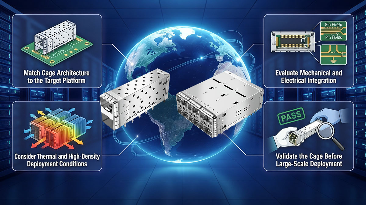
Αντιστοίχιση αρχιτεκτονικής κλουβιού με την πλατφόρμα-στόχο
Το πρώτο βήμα είναι να ταιριάξετε το LINK-PP Αρχιτεκτονική κλωβού SFP/QSFP με την προβλεπόμενη πλατφόρμα υποδοχής και τον τύπο πομποδέκτη. Η σωστή αντιστοίχιση απαιτεί συντονισμό μεταξύ του κλωβού, του ηλεκτρικού συνδέσμου, της πλακέτας τυπωμένου κυκλώματος, του πλαισίου και του ανοίγματος του μπροστινού πίνακα.
Οι μηχανικοί θα πρέπει να επαληθεύσουν διάφορα σημεία πριν προχωρήσουν:
- Συντελεστής μορφής πομποδέκτη: Προσδιορίστε εάν η πλατφόρμα απαιτεί κλωβό οικογένειας SFP ή οικογένειας QSFP και επιβεβαιώστε την προβλεπόμενη διαμόρφωση μονάδας.
- Μηχανικές διαστάσεις: Συγκρίνετε τις διαστάσεις του κλωβού με την πλακέτα τυπωμένου κυκλώματος, το πλαίσιο, το πλαίσιο και τον διαθέσιμο χώρο εγκατάστασης.
- Διαμόρφωση τοποθέτησης: Επιβεβαιώστε ότι η δομή στήριξης του κλωβού ταιριάζει με το σχεδιασμό της πλακέτας τυπωμένου κυκλώματος του κεντρικού υπολογιστή.
- Θέση σύνδεσης: Επαληθεύστε την ευθυγράμμιση μεταξύ του κλωβού και του αντίστοιχου ηλεκτρικού συνδετήρα.
- Διαρρύθμιση λιμένα: Ελέγξτε εάν η διαμόρφωση του κλωβού υποστηρίζει την απαιτούμενη πυκνότητα και απόσταση θυρών.
- Πρόσβαση στην υπηρεσία: Βεβαιωθείτε ότι οι γλωττίδες έλξης, τα μάνδαλα και οι μηχανισμοί αφαίρεσης του πομποδέκτη παραμένουν προσβάσιμα μετά την εγκατάσταση.
Αυτή η διαδικασία αντιστοίχισης είναι ιδιαίτερα σημαντική σε πυκνούς διακόπτες τεχνητής νοημοσύνης και εξοπλισμό edge 5G. Ένα κλουβί μπορεί να είναι συμβατό με έναν πομποδέκτη σε επίπεδο μορφής, ενώ παράλληλα να δημιουργεί προβλήματα με την τοποθέτηση της πλακέτας τυπωμένου κυκλώματος, τις γειτονικές θύρες ή την πρόσβαση στον μπροστινό πίνακα. Επομένως, η μηχανική επαλήθευση σε επίπεδο πλατφόρμας θα πρέπει να προηγείται της ανάπτυξης.
Αξιολόγηση Μηχανικής και Ηλεκτρικής Ενσωμάτωσης
Η μηχανική και ηλεκτρική ολοκλήρωση θα πρέπει να αξιολογούνται μαζί, επειδή ο κλωβός καθορίζει το φυσικό περιβάλλον γύρω από τον κεντρικό σύνδεσμο και τον πομποδέκτη. LINK-PP Συνεπώς, η αξιολόγηση του κλωβού SFP/QSFP θα πρέπει να λαμβάνει υπόψη όχι μόνο τη συγκράτηση και την ακρίβεια των διαστάσεων, αλλά και τη γείωση, τη θωράκιση και τη σχέση μεταξύ του κλωβού και της πλακέτας τυπωμένου κυκλώματος (PCB).
Οι βασικοί τομείς αξιολόγησης περιλαμβάνουν:
- Απόδοση διατήρησης: Προσδιορίστε εάν ο κλωβός διατηρεί με ασφάλεια τη θέση του πομποδέκτη κατά την κανονική λειτουργία.
- Συμπεριφορά εισαγωγής και εξαγωγής: Αξιολογήστε εάν οι μονάδες μπορούν να εγκατασταθούν και να αφαιρεθούν με συνέπεια χωρίς υπερβολική μηχανική καταπόνηση.
- Ευθυγραμμία: Επαληθεύστε τη σταθερή τοποθέτηση μεταξύ του πομποδέκτη και της υποδοχής κεντρικού υπολογιστή.
- Διεπαφή γείωσης: Εξετάστε πώς ο κλωβός ενσωματώνεται με την προβλεπόμενη αρχιτεκτονική γείωσης της πλατφόρμας.
- Θωράκιση EMI: Αξιολογήστε τη συμβολή του κλωβού στο αγώγιμο περιβάλλον θωράκισης γύρω από διεπαφές υψηλής ταχύτητας.
- Ενσωμάτωση PCB: Επιβεβαιώστε ότι η τοποθέτηση του κλωβού δεν έρχεται σε σύγκρουση με τη δρομολόγηση υψηλής ταχύτητας ή άλλα στοιχεία σε επίπεδο πλακέτας.
Αυτοί οι παράγοντες είναι ιδιαίτερα σημαντικοί για τα δίκτυα τεχνητής νοημοσύνης υψηλής ταχύτητας, επειδή οι πυκνές διεπαφές μπορούν να αφήνουν περιορισμένο περιθώριο για μηχανικά και ηλεκτρικά περιθώρια σχεδιασμού. Συνεπώς, ο κλωβός θα πρέπει να αξιολογείται μαζί με τον κεντρικό σύνδεσμο και την πλακέτα τυπωμένου κυκλώματος (PCB) αντί να αντιμετωπίζεται ως ανεξάρτητο στοιχείο.
Λάβετε υπόψη τις θερμικές συνθήκες και τις συνθήκες ανάπτυξης υψηλής πυκνότητας
Οι θερμικές συνθήκες και οι συνθήκες πυκνότητας θα πρέπει να αξιολογούνται σύμφωνα με το πραγματικό περιβάλλον στο οποίο LINK-PP Θα λειτουργήσει το κλουβί SFP/QSFP. Οι πλατφόρμες τεχνητής νοημοσύνης υψηλής πυκνότητας και 5G μπορούν να τοποθετήσουν πολλαπλούς πομποδέκτες κοντά ο ένας στον άλλο, καθιστώντας σημαντική τη ροή αέρα, την ισχύ της μονάδας και την απόσταση μεταξύ των γειτονικών θυρών.
Μια πρακτική αξιολόγηση θα πρέπει να καλύπτει:
- Θερμικό φορτίο πομποδέκτη: Λάβετε υπόψη την αναμενόμενη παραγωγή ισχύος και θερμότητας από τις μονάδες που είναι εγκατεστημένες στο κλουβί.
- Διαδρομή ροής αέρα: Βεβαιωθείτε ότι η διάταξη του κλωβού δεν περιορίζει άσκοπα τη διαδρομή ψύξης του συστήματος.
- Πυκνότητα λιμένα: Αξιολογήστε τη συσσώρευση θερμότητας και τη φυσική απόσταση όταν υπάρχουν πολλαπλά κλουβιά.
- Θερμικό διάκενο εξαρτημάτων: Ελέγξτε τον χώρο για ψύκτρες μονάδων και σχετικές δομές ψύξης, όπου ισχύει.
- Συνθήκες πλαισίου: Αξιολογήστε τον κλωβό κάτω από το πραγματικό περίβλημα, την κατεύθυνση της ροής του αέρα και τη διαμόρφωση ψύξης.
Για τα clusters τεχνητής νοημοσύνης, αυτές οι παράμετροι αποκτούν ολοένα και μεγαλύτερη σημασία καθώς οι οπτικές διεπαφές υψηλής ταχύτητας αναπτύσσονται σε μεγαλύτερη πυκνότητα. Στον εξοπλισμό edge 5G, τα συμπαγή σχέδια πλαισίου μπορούν να δημιουργήσουν παρόμοιους περιορισμούς. Επομένως, ο κλωβός πρέπει να αξιολογηθεί ως μέρος του θερμικού περιβάλλοντος της μονάδας και του πλαισίου.
Επικύρωση του κλωβού πριν από την ανάπτυξη μεγάλης κλίμακας
Πριν από την ανάπτυξη σε μεγάλη κλίμακα, οι μηχανικοί θα πρέπει να επικυρώσουν ολόκληρο το συγκρότημα κλωβού υπό αντιπροσωπευτικές μηχανικές, θερμικές, ηλεκτρομαγνητικές τάσεις και συνθήκες λειτουργίας υψηλής ταχύτητας. Η συμβατότητα με τα φύλλα δεδομένων είναι ένα σημαντικό σημείο εκκίνησης, αλλά οι φυσικές δοκιμές και οι δοκιμές σε επίπεδο συστήματος παρέχουν ισχυρότερες αποδείξεις ότι ο κλωβός θα λειτουργήσει όπως προβλέπεται στην πλατφόρμα-στόχο.
Μια πρακτική ακολουθία επικύρωσης μπορεί να περιλαμβάνει:
- Μηχανική δοκιμή: Επαληθεύστε την εισαγωγή, την εξαγωγή, τη συγκράτηση, την ευθυγράμμιση και τη φυσική εφαρμογή σε όλες τις αντιπροσωπευτικές θύρες.
- Θερμικές δοκιμές: Μετρήστε το περιβάλλον του κλωβού και του πομποδέκτη υπό ρεαλιστικά λειτουργικά φορτία και συνθήκες ροής αέρα.
- Δοκιμές EMI/EMC: Αξιολογήστε ολόκληρο το συγκρότημα κεντρικού υπολογιστή με την προβλεπόμενη διαμόρφωση γείωσης και θωράκισης.
- Δοκιμή σύνδεσης υψηλής ταχύτητας: Επικυρώστε τον συνδυασμό κλωβού, συνδέσμου, πλακέτας τυπωμένου κυκλώματος και πομποδέκτη χρησιμοποιώντας την πραγματική πλατφόρμα κεντρικού υπολογιστή.
- Δοκιμές κύκλου λειτουργίας: Επαναλάβετε την εισαγωγή και την αφαίρεση της μονάδας για να αξιολογήσετε τη μηχανική συνέπεια κατά τη διάρκεια του αναμενόμενου κύκλου ζωής συντήρησης.
Αυτή η διαδικασία επικύρωσης βοηθά στον εντοπισμό προβλημάτων ενσωμάτωσης προτού αυτά εξαπλωθούν σε ένα μεγάλο σύμπλεγμα τεχνητής νοημοσύνης ή σε κατανεμημένη ανάπτυξη 5G. LINK-PP Για τις λύσεις κλωβού SFP/QSFP, η πιο ουσιαστική αξιολόγηση είναι επομένως αυτή που συνδυάζει τις προδιαγραφές των εξαρτημάτων με την πραγματική συμπεριφορά της πλατφόρμας και τις αναμενόμενες συνθήκες λειτουργίας.
🥏 Ποια είναι τα συνηθισμένα λάθη σχεδιασμού κλωβών SFP/QSFP στις αναπτύξεις τεχνητής νοημοσύνης και 5G;
Τα πιο συνηθισμένα λάθη σχεδιασμού κλωβού SFP/QSFP σε εφαρμογές τεχνητής νοημοσύνης και 5G συμβαίνουν όταν οι μηχανικοί αξιολογούν τον κλωβό μόνο ως μηχανική βάση και όχι ως μέρος της πλήρους διεπαφής συνδεσιμότητας υψηλής ταχύτητας. Προβλήματα μπορεί να προκύψουν από ανεπαρκή μηχανική επικύρωση, υπερβολική πυκνότητα θυρών, ανεπαρκή θερμικό σχεδιασμό ή μη λήψη υπόψη της επαναλαμβανόμενης συντήρησης. Αυτά τα ζητήματα μπορούν να επηρεάσουν την προσβασιμότητα του πομποδέκτη, τη σταθερότητα του συνδέσμου, τη ροή αέρα, την απόδοση των ηλεκτρομαγνητικών παρεμβολών (EMI) και τη μακροπρόθεσμη λειτουργική αξιοπιστία.
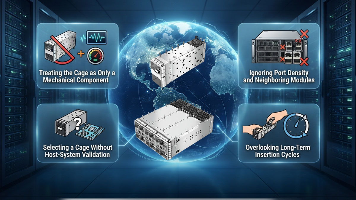
Αντιμετώπιση του κλωβού ως μόνο μηχανικού εξαρτήματος
Η αντιμετώπιση του κλωβού SFP/QSFP μόνο ως μηχανικού εξαρτήματος είναι ένα συνηθισμένο λάθος, επειδή ο κλωβός αλληλεπιδρά επίσης με τη γείωση, τη θωράκιση, την τοποθέτηση των συνδέσμων, τη διάταξη της πλακέτας τυπωμένου κυκλώματος (PCB) και τις θερμικές συνθήκες. Ο ρόλος του θα πρέπει να αξιολογείται εντός της πλήρους διεπαφής του κεντρικού υπολογιστή.
Οι μηχανικοί θα πρέπει να αποφεύγουν τον διαχωρισμό του κλωβού από αυτά τα σχετικά στοιχεία σχεδιασμού:
- Ενσωμάτωση ηλεκτρικού συνδέσμου: Η γεωμετρία του κλωβού και η τοποθέτηση του συνδετήρα πρέπει να συνεργάζονται για να διατηρούν συνεπή εμπλοκή του πομποδέκτη.
- Αρχιτεκτονική γείωσης: Ο κλωβός μπορεί να αποτελεί μέρος της αγώγιμης διαδρομής που χρησιμοποιείται για τη στρατηγική θωράκισης και γείωσης του συστήματος.
- Περιβάλλον EMI: Οι οπτικές θύρες υψηλής πυκνότητας απαιτούν συντονισμένο μηχανικό και ηλεκτρομαγνητικό σχεδιασμό.
- Διάταξη PCB: Η τοποθέτηση του κλουβιού πρέπει να προσαρμόζεται σε ίχνη υψηλής ταχύτητας και σε κοντινά εξαρτήματα.
- Θερμικός σχεδιασμός: Ο κλωβός και οι εγκατεστημένοι πομποδέκτες λειτουργούν στο ίδιο περιβάλλον ροής αέρα και διαχείρισης θερμότητας.
Αυτό είναι ιδιαίτερα σημαντικό σε clusters τεχνητής νοημοσύνης, όπου οι διεπαφές υψηλής ταχύτητας είναι πυκνά συγκεντρωμένες, και σε συστήματα 5G edge, όπου ο συμπαγής εξοπλισμός μπορεί να αφήνει περιορισμένα περιθώρια σχεδιασμού. Η αξιολόγηση του κλωβού μεμονωμένα μπορεί επομένως να παραβλέψει προβλήματα ενσωμάτωσης που γίνονται ορατά μόνο σε επίπεδο συστήματος.
Αγνόηση της πυκνότητας θυρών και των γειτονικών ενοτήτων
Η αγνόηση της πυκνότητας των θυρών και των γειτονικών μονάδων μπορεί να δημιουργήσει μηχανικά, θερμικά και προβλήματα λειτουργικότητας, ακόμη και όταν κάθε μεμονωμένος κλωβός πληροί τις βασικές διαστατικές του απαιτήσεις. Σε ένα μπροστινό πάνελ υψηλής πυκνότητας, η αλληλεπίδραση μεταξύ γειτονικών κλωβών μπορεί να είναι εξίσου σημαντική με τις προδιαγραφές ενός μόνο κλωβού.
Τα κοινά ζητήματα περιλαμβάνουν:
- Περιορισμένη πρόσβαση σε λειτουργική μονάδα: Τα κλουβιά σε κοντινή απόσταση μεταξύ τους μπορούν να δυσχεράνουν τη λειτουργία των μανδάλων ή των γλωττίδων έλξης.
- Παρεμβολές καλωδίων: Οι πυκνές οπτικές θύρες ενδέχεται να αφήνουν ανεπαρκή χώρο για τους συνδέσμους οπτικών ινών και τη δρομολόγηση καλωδίων.
- Περιορισμοί ροής αέρα: Μια σφιχτά συσκευασμένη διάταξη κλωβού μπορεί να περιπλέξει τη ροή του αέρα γύρω από γεμάτους πομποδέκτες.
- Συσσώρευση θερμότητας: Οι γειτονικές μονάδες υψηλής ισχύος μπορούν να αυξήσουν τα τοπικά θερμικά φορτία.
- Μηχανική παρεμβολή: Γειτονικοί κλωβοί ή μονάδες ενδέχεται να επηρεάσουν την εισαγωγή και την εξαγωγή.
Για τους διακόπτες τεχνητής νοημοσύνης (AI switches) και τις πλατφόρμες edge 5G, η πυκνότητα των θυρών θα πρέπει επομένως να αξιολογείται σε επίπεδο πλήρους μπροστινού πίνακα. Οι μηχανικοί πρέπει να λαμβάνουν υπόψη τον τρόπο συμπεριφοράς των κλωβών όταν κάθε γειτονική θύρα είναι γεμάτη, αντί να επικυρώνουν μια κενή ή απομονωμένη διαμόρφωση κλωβού.
Επιλογή κλωβού χωρίς επικύρωση συστήματος κεντρικού υπολογιστή
Η επιλογή ενός κλωβού SFP/QSFP χωρίς την επικύρωσή του σε σχέση με το σύστημα υποδοχής μπορεί να οδηγήσει σε προβλήματα συμβατότητας που δεν είναι εμφανή μόνο από τον ονομαστικό συντελεστή μορφής. Ένας κλωβός μπορεί να υποστηρίζει την προβλεπόμενη οικογένεια πομποδεκτών, ενώ εξακολουθεί να είναι ακατάλληλος για μια συγκεκριμένη πλακέτα τυπωμένου κυκλώματος, υποδοχή, πλαίσιο ή πλαίσιο.
Ένας πλήρης έλεγχος συμβατότητας θα πρέπει να καλύπτει:
- Αποτύπωμα και τοποθέτηση πλακέτας τυπωμένου κυκλώματος: Επιβεβαιώστε ότι ο κλωβός μπορεί να εγκατασταθεί σύμφωνα με το σχέδιο της πλακέτας κεντρικού υπολογιστή.
- Ευθυγράμμιση συνδετήρα: Επαληθεύστε τη φυσική σχέση μεταξύ του κλωβού και του ηλεκτρικού συνδετήρα.
- Διαστάσεις μπροστινού πάνελ: Ελέγξτε τον κλωβό σε σχέση με το πραγματικό πλαίσιο και το άνοιγμα της στεφάνης.
- Διάκενο παρακείμενων εξαρτημάτων: Εντοπίστε πιθανές παρεμβολές με ψύκτρες, υποδοχές, καλώδια και άλλα εξαρτήματα.
- Εγκατάσταση πομποδέκτη: Ελέγξτε τον πραγματικό τύπο μονάδας που προορίζεται για ανάπτυξη αντί να βασίζεστε αποκλειστικά σε προδιαγραφές διαστάσεων.
Αυτή η διάκριση είναι σημαντική επειδή η συμβατότητα με τους παράγοντες μορφής και η συμβατότητα του συστήματος δεν είναι πανομοιότυπες. Η επικύρωση σε επίπεδο κεντρικού υπολογιστή μπορεί να αποκαλύψει μηχανικά ή ηλεκτρικά προβλήματα ενσωμάτωσης πριν η ίδια διαμόρφωση κλουβιού αναπαραχθεί σε ένα μεγάλο σύμπλεγμα τεχνητής νοημοσύνης ή σε πολλαπλές τοποθεσίες 5G edge.
Παραβλέποντας τους μακροπρόθεσμους κύκλους εισαγωγής
Η παράβλεψη μακροπρόθεσμων κύκλων εισαγωγής μπορεί να δημιουργήσει προβλήματα αξιοπιστίας, επειδή οι οπτικοί πομποδέκτες ενδέχεται να αφαιρούνται και να εγκαθίστανται επανειλημμένα κατά τη διάρκεια συντήρησης, δοκιμών, αντιμετώπισης προβλημάτων και αναβαθμίσεων δικτύου. Ένας κλωβός που λειτουργεί επαρκώς κατά την αρχική εγκατάσταση ενδέχεται να χρειάζεται πρόσθετη επικύρωση για επαναλαμβανόμενες λειτουργίες σέρβις.
Οι κύριοι κίνδυνοι που σχετίζονται με την ανεπαρκή εξέταση του κύκλου εισαγωγής περιλαμβάνουν:
- Υποβάθμιση διατήρησης: Η επαναλαμβανόμενη μηχανική φόρτιση μπορεί να επηρεάσει τον τρόπο με τον οποίο οι μονάδες παραμένουν ασφαλώς τοποθετημένες.
- Αλλαγές ευθυγράμμισης: Η μηχανική παραμόρφωση μπορεί να επηρεάσει τη θέση του πομποδέκτη σε σχέση με τον κεντρικό σύνδεσμο.
- Αυξημένη δύναμη εισαγωγής: Οι αλλαγές στη γεωμετρία του κλωβού μπορούν να δυσχεράνουν την επακόλουθη αντικατάσταση των μονάδων.
- Ασυνέπεια υπηρεσίας: Διαφορετικές θύρες ενδέχεται να αναπτύξουν διαφορετική μηχανική συμπεριφορά μετά από επαναλαμβανόμενες εργασίες συντήρησης.
- Τάση συνδετήρα: Η κακώς ελεγχόμενη εισαγωγή ή εξαγωγή μπορεί να ασκήσει πρόσθετο μηχανικό φορτίο στη διεπαφή του κεντρικού υπολογιστή.
Αυτό το ζήτημα είναι ιδιαίτερα σημαντικό για την υποδομή Τεχνητής Νοημοσύνης, επειδή τα μεγάλα clusters περιέχουν πολλές οπτικές θύρες που ενδέχεται να υποβάλλονται σε συντήρηση σε διαφορετικές χρονικές στιγμές. Είναι εξίσου σημαντικό για τις κατανεμημένες αναπτύξεις 5G σε front-haul περιοχές, όπου οι τεχνικοί πεδίου χρειάζονται προβλέψιμη πρόσβαση και αντικατάσταση μονάδων. Η αξιολόγηση της ανθεκτικότητας της εισαγωγής ως μέρος της αρχικής πιστοποίησης του κλωβού μπορεί επομένως να βοηθήσει στην υποστήριξη μιας πιο συνεπούς μακροπρόθεσμης λειτουργίας.
🥏 Πώς πρέπει οι μηχανικοί τεχνητής νοημοσύνης και 5G να επιλέξουν ένα κλουβί SFP/QSFP;
Οι μηχανικοί τεχνητής νοημοσύνης και 5G θα πρέπει να επιλέξουν ένα κλουβί SFP/QSFP ξεκινώντας με τον απαιτούμενο παράγοντα μορφής πομποδέκτη και στη συνέχεια επικυρώνοντας τη μηχανική συμβατότητα, την πυκνότητα θύρας, την ηλεκτρομαγνητική παρέκκλιση/γείωση, τις θερμικές συνθήκες και τις απαιτήσεις μακροπρόθεσμης εξυπηρέτησης. Για συνδεσιμότητα front-haul συμπλέγματος τεχνητής νοημοσύνης και άκρων 5G, το καλύτερο κλουβί δεν είναι απλώς αυτό που δέχεται την προβλεπόμενη μονάδα. Πρέπει να ενσωματώνεται σωστά με την πλακέτα κεντρικού υπολογιστή, τον σύνδεσμο, το πλαίσιο, το σύστημα ροής αέρα και το περιβάλλον συντήρησης.
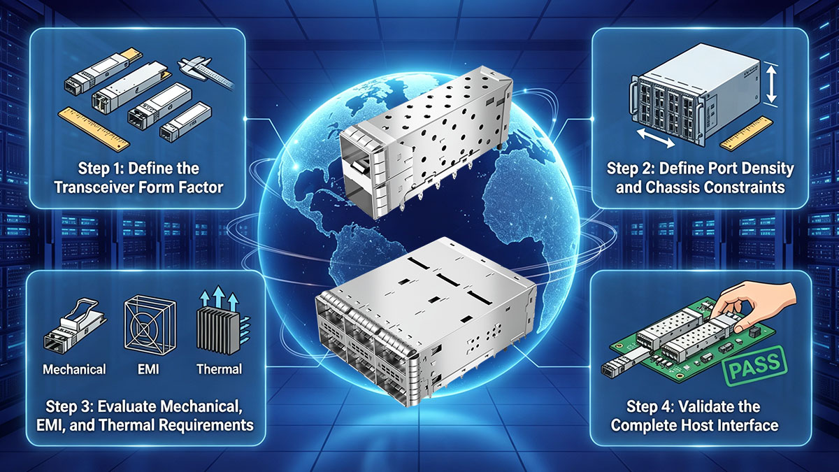
Βήμα 1: Ορίστε τον συντελεστή μορφής του πομποδέκτη
Το πρώτο βήμα είναι να προσδιοριστεί ο ακριβής συντελεστής μορφής του πομποδέκτη που θα χρησιμοποιήσει η πλατφόρμα. Οι μονάδες της οικογένειας SFP και της οικογένειας QSFP έχουν διαφορετικές μηχανικές διεπαφές, επομένως ο κλωβός πρέπει να ταιριάζει με την προβλεπόμενη αρχιτεκτονική της μονάδας πριν αξιολογηθούν άλλα χαρακτηριστικά.
Οι μηχανικοί θα πρέπει να επιβεβαιώσουν:
- Διεπαφή οικογένειας SFP ή οικογένειας QSFP: Προσδιορίστε την απαιτούμενη οικογένεια κλωβών πριν επιλέξετε μια συγκεκριμένη διαμόρφωση κλωβού.
- Τύπος ενότητας-στόχου: Προσδιορίστε τον οπτικό πομποδέκτη ή τη μονάδα που θα καταλάβει το κλουβί.
- Σύνδεση κεντρικού υπολογιστή: Βεβαιωθείτε ότι ο κλωβός και ο ηλεκτρικός σύνδεσμος έχουν σχεδιαστεί για να λειτουργούν μαζί.
- Μηχανικές διαστάσεις: Επιβεβαιώστε το ύψος, το πλάτος, το βάθος του κλωβού και τις σχετικές διαστάσεις τοποθέτησης.
- Πρόσβαση στην ενότητα: Ελέγξτε ότι ο προβλεπόμενος μηχανισμός μανδάλου ή γλωττίδας μπορεί να λειτουργήσει μετά την εγκατάσταση.
Αυτό το αρχικό βήμα καθορίζει τη βασική φυσική συμβατότητα του κλωβού SFP/QSFP. Μόλις επιβεβαιωθεί ο συντελεστής μορφής, οι μηχανικοί μπορούν να προχωρήσουν στους περιορισμούς που δημιουργούνται από την πλατφόρμα-στόχο.
Βήμα 2: Ορισμός περιορισμών πυκνότητας θυρών και πλαισίου
Η πυκνότητα των θυρών θα πρέπει να αξιολογείται πριν από την οριστικοποίηση της διάταξης του κλωβού, επειδή οι διακόπτες AI και ο εξοπλισμός edge 5G συχνά χρειάζεται να φιλοξενούν πολλές οπτικές διεπαφές εντός περιορισμένου χώρου στο πλαίσιο. Μια διαμόρφωση κλωβού πρέπει να παρέχει επαρκή χώρο για μονάδες, καλώδια, ροή αέρα και πρόσβαση στη συντήρηση.
Η αξιολόγηση θα πρέπει να καλύπτει:
- Αριθμός λιμένων: Προσδιορίστε πόσες διεπαφές SFP/QSFP απαιτεί η πλατφόρμα.
- Διάταξη κλουβιού: Επιλέξτε μια κατάλληλη διαμόρφωση μίας σειράς, στοίβαξης ή άλλη ανάλογα με την αρχιτεκτονική του πλαισίου.
- Απόσταση θυρών: Επαληθεύστε την απόσταση μεταξύ γειτονικών πομποδεκτών και κλωβών.
- Πρόσβαση οπτικών ινών: Αφήστε επαρκή χώρο για οπτικές υποδοχές και δρομολόγηση καλωδίων.
- Δυνατότητα συντήρησης μπροστινού πίνακα: Βεβαιωθείτε ότι οι τεχνικοί μπορούν να αφαιρέσουν μεμονωμένες μονάδες χωρίς περιττή παρέμβαση.
- Ενσωμάτωση πλαισίου: Επιβεβαιώστε τη συμβατότητα με το πλαίσιο, το περίβλημα, την πλακέτα τυπωμένου κυκλώματος και άλλα εξαρτήματα του μπροστινού πίνακα.
Για τους διακόπτες συμπλέγματος τεχνητής νοημοσύνης, η μεγιστοποίηση της πυκνότητας θυρών χωρίς να λαμβάνεται υπόψη η πρόσβαση και η ροή αέρα μπορεί να δημιουργήσει προκλήσεις συντήρησης και θερμότητας. Για τις πλατφόρμες edge 5G, οι συμπαγείς διαστάσεις του εξοπλισμού μπορούν να δημιουργήσουν παρόμοιους περιορισμούς. Η πυκνότητα των θυρών θα πρέπει επομένως να εξισορροπείται με τις πρακτικές απαιτήσεις εγκατάστασης και λειτουργίας.
Βήμα 3: Αξιολόγηση μηχανικών, ηλεκτρομαγνητικών και θερμικών απαιτήσεων
Αφού ορίσουν τη φυσική αρχιτεκτονική, οι μηχανικοί θα πρέπει να αξιολογήσουν τη μηχανική αντοχή του κλωβού, τα χαρακτηριστικά θωράκισης και γείωσης έναντι ηλεκτρομαγνητικών παρεμβολών (EMI), καθώς και τη θερμική ενσωμάτωση. Αυτοί οι παράγοντες αποκτούν ολοένα και μεγαλύτερη σημασία όταν οι οπτικές μονάδες υψηλής ταχύτητας λειτουργούν σε υψηλή πυκνότητα.
Μια πρακτική αξιολόγηση θα πρέπει να επικεντρώνεται στους ακόλουθους τομείς:
- Μηχανική αξιοπιστία: Αξιολογήστε τη συγκράτηση, την ευθυγράμμιση, τη σταθερότητα τοποθέτησης και τους αναμενόμενους κύκλους εισαγωγής/αφαίρεσης.
- Θωράκιση EMI: Εξετάστε πώς ο κλωβός ενσωματώνεται με την αρχιτεκτονική ηλεκτρομαγνητικής θωράκισης της πλατφόρμας υποδοχής.
- Γείωση: Επαληθεύστε την προβλεπόμενη διεπαφή γείωσης μεταξύ κλωβού και PCB ή μεταξύ κλωβού και πλαισίου.
- Ροή αέρα: Προσδιορίστε εάν η διάταξη του κλωβού υποστηρίζει τη διαδρομή ψύξης του συστήματος κεντρικού υπολογιστή.
- Θερμική απόσταση: Ελέγξτε τη συμβατότητα με τις ψύκτρες του πομποδέκτη και τα γύρω θερμικά εξαρτήματα.
- Λειτουργία υψηλής πυκνότητας: Αξιολογήστε τις θερμικές και ηλεκτρομαγνητικές συνθήκες με γειτονικές θύρες κατοικημένες.
Αυτές οι απαιτήσεις θα πρέπει να εξετάζονται μαζί και όχι ανεξάρτητα. Για παράδειγμα, η αύξηση της πυκνότητας του κλωβού μπορεί να βελτιώσει την χωρητικότητα του μπροστινού πίνακα, μειώνοντας παράλληλα τη ροή του αέρα ή την απόσταση λειτουργίας. Ομοίως, ένας μηχανικά κατάλληλος κλωβός εξακολουθεί να απαιτεί κατάλληλη γείωση και ενσωμάτωση θωράκισης εντός της πλατφόρμας υποδοχής.
Βήμα 4: Επικύρωση πλήρους διεπαφής κεντρικού υπολογιστή
Το τελικό βήμα είναι η επικύρωση ολόκληρου του συγκροτήματος κλωβού SFP/QSFP στο πραγματικό ή αντιπροσωπευτικό περιβάλλον κεντρικού υπολογιστή. Αυτό είναι σημαντικό επειδή η συμβατότητα σε επίπεδο στοιχείων δεν αποδεικνύει αυτόματα τη συμβατότητα σε επίπεδο συστήματος.
Μια πρακτική ακολουθία επικύρωσης περιλαμβάνει:
- Μηχανική επικύρωση: Επιβεβαιώστε τη φυσική εφαρμογή, την ευθυγράμμιση, τη συγκράτηση, την εισαγωγή και την εξαγωγή.
- Επικύρωση πυκνότητας θύρας: Συμπληρώστε τις γειτονικές θύρες και επαληθεύστε την πρόσβαση της μονάδας, το διάκενο καλωδίων και τις μηχανικές παρεμβολές.
- Θερμική επικύρωση: Ελέγξτε τον συνδυασμό κλωβού και πομποδέκτη υπό αντιπροσωπευτικές συνθήκες φορτίου και ροής αέρα.
- Επικύρωση EMI/EMC: Αξιολογήστε ολόκληρη τη συναρμολόγηση χρησιμοποιώντας την προβλεπόμενη διαμόρφωση γείωσης και θωράκισης.
- Επικύρωση υψηλής ταχύτητας: Ελέγξτε τον πραγματικό συνδυασμό κλωβού, συνδέσμου, πλακέτας τυπωμένου κυκλώματος και πομποδέκτη υπό τις συνθήκες σύνδεσης-στόχου.
- Επικύρωση κύκλου υπηρεσίας: Επαναλάβετε τις εργασίες εισαγωγής και αφαίρεσης για να αξιολογήσετε τη μηχανική συνέπεια καθ' όλη τη διάρκεια του αναμενόμενου κύκλου ζωής συντήρησης.
Αυτό το τελικό βήμα επικύρωσης είναι ιδιαίτερα πολύτιμο για μεγάλα clusters τεχνητής νοημοσύνης και κατανεμημένες αναπτύξεις 5G, επειδή ένα μικρό πρόβλημα διεπαφής μπορεί να αποκτήσει λειτουργική σημασία όταν επαναλαμβάνεται σε πολλές θύρες ή τοποθεσίες. Επομένως, μια συστηματική διαδικασία επιλογής βοηθά τους μηχανικούς να επιλέξουν ένα κλουβί SFP/QSFP με βάση το πλήρες περιβάλλον συνδεσιμότητας και όχι μόνο τη συμβατότητα των παραγόντων μορφής.
🥏 Συμπέρασμα
LINK-PPΤο κλουβί SFP/QSFP της εταιρείας παίζει σημαντικό ρόλο στην υποστήριξη αξιόπιστης συνδεσιμότητας υψηλής ταχύτητας για clusters AI, 5G front-haul και πλατφόρμες δικτύωσης edge. Ενώ το κλουβί δεν καθορίζει άμεσα την απόδοση της οπτικής μετάδοσης, η μηχανική του δομή, η ευθυγράμμιση του πομποδέκτη, η συγκράτηση, η θωράκιση EMI, η γείωση, η θερμική ενσωμάτωση και η ανθεκτικότητα εισαγωγής συμβάλλουν στη συνολική σταθερότητα της διεπαφής κεντρικού υπολογιστή. Καθώς τα δίκτυα AI και 5G κινούνται προς υψηλότερη πυκνότητα θυρών και ταχύτερες οπτικές συνδέσεις, αυτές οι παράμετροι αποκτούν ολοένα και μεγαλύτερη σημασία.
Τα βασικά σημεία για τους μηχανικούς είναι:
- Ομάδες Τεχνητής Νοημοσύνης: Η υψηλή πυκνότητα θυρών, οι διεπαφές υψηλής ταχύτητας, τα θερμικά φορτία και η συχνή συντήρηση καθιστούν την ενσωμάτωση σε κλουβί κρίσιμη.
- 5G από μπροστά: Ο συμπαγής εξοπλισμός, η κατανεμημένη ανάπτυξη, η συντήρηση πεδίου και οι αξιόπιστες οπτικές διεπαφές αυξάνουν τις μηχανικές απαιτήσεις.
- Αξιολόγηση κλουβιού: Η συμβατότητα με τους παράγοντες μορφής θα πρέπει να συνδυάζεται με μηχανική, ηλεκτρομαγνητική, θερμική, επικύρωση ακεραιότητας σήματος και επικύρωση συστήματος κεντρικού υπολογιστή.
- Μακροπρόθεσμη αξιοπιστία: Η ανθεκτικότητα του κύκλου εισαγωγής, η διατήρηση, η ευθυγράμμιση και η προσβασιμότητα της υπηρεσίας θα πρέπει να λαμβάνονται υπόψη πριν από την ανάπτυξη.
Για τους μηχανικούς που αξιολογούν στοιχεία οπτικής συνδεσιμότητας για απαιτητικά περιβάλλοντα δικτύωσης, το LINK-PP Επίσημο κατάστημα παρέχει ένα πρακτικό σημείο εκκίνησης για την εξερεύνηση συμβατών οπτικών μονάδων και σχετικών λύσεων συνδεσιμότητας. Η επιλογή του κατάλληλου κλωβού SFP/QSFP σε συνδυασμό με τον σωστό σχεδιασμό πομποδέκτη και πλατφόρμας υποδοχής μπορεί να βοηθήσει στη δημιουργία μιας πιο αξιόπιστης βάσης για cluster τεχνητής νοημοσύνης υψηλής πυκνότητας και συνδεσιμότητα 5G edge.