



































Δυσκολεύεται το κέντρο δεδομένων σας να ανταποκριθεί στις συνεχώς αυξανόμενες απαιτήσεις για μεγαλύτερες ταχύτητες και υψηλότερο εύρος ζώνης; Καθώς τα δίκτυα επεκτείνονται, οι παραδοσιακές μέθοδοι καλωδίωσης γίνονται γρήγορα πολύ ογκώδεις και πολύπλοκες για αποτελεσματική διαχείριση. Αυτός είναι ο λόγος για τον οποίο η αναβάθμιση σε σύστημα οπτικών ινών με σύνδεσμο MTP έχει γίνει το απόλυτο πρότυπο σχεδιασμού για σύγχρονα περιβάλλοντα υψηλής πυκνότητας.
Πώς όμως διασφαλίζετε ότι η μετεγκατάσταση υψηλής πυκνότητας θα γίνει ομαλά χωρίς να προκύψει απώλεια σήματος ή χάος πολικότητας; Η εφαρμογή αυτών των προηγμένων συστημάτων απαιτεί μια καλή κατανόηση συγκεκριμένων προτύπων του κλάδου, από την επιλογή του σωστού φύλου ακίδων έως την εξειδίκευση στη διαχείριση καλωδίων. Ας εμβαθύνουμε στα βασικά πρότυπα σχεδιασμού που πρέπει να γνωρίζετε για να δημιουργήσετε ένα άψογο, μελλοντικά βιώσιμο δίκτυο.
🍃 Τι είναι ο σύνδεσμος οπτικών ινών MTP και πώς λειτουργεί
Η κατανόηση της βασικής τεχνολογίας πίσω από την καλωδίωση υψηλής πυκνότητας είναι απαραίτητη για την οικοδόμηση μιας αποτελεσματικής υποδομής δικτύου. Ενοποιώντας πολλαπλές οπτικές ίνες σε μία μόνο διεπαφή, ένα σύστημα οπτικών ινών σύνδεσης MTP μειώνει δραστικά την ακαταστασία των καλωδίων, ενισχύοντας παράλληλα τις δυνατότητες μετάδοσης δεδομένων. Η διερεύνηση του τρόπου λειτουργίας αυτών των προηγμένων εξαρτημάτων αποκαλύπτει τα πραγματικά θεμέλια των σύγχρονων κέντρων δεδομένων υψηλής ταχύτητας.
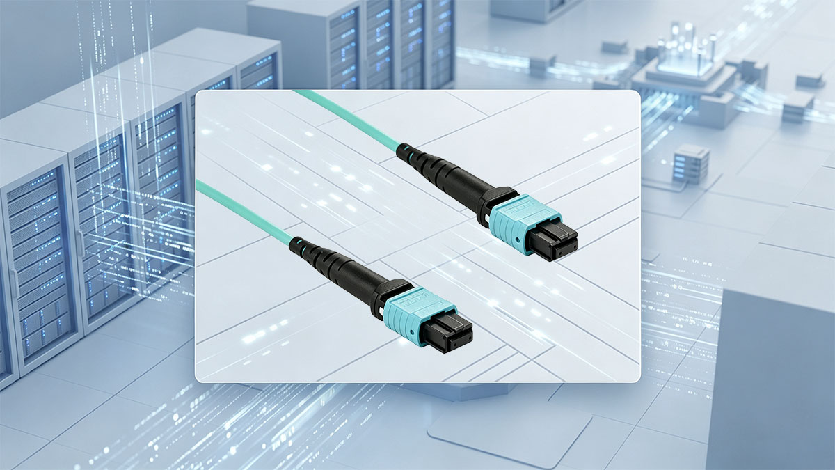
Τα βασικά των συνδέσμων MTP και των καλωδίων οπτικών ινών
Ένας σύνδεσμος οπτικής ίνας MTP είναι μια λύση υψηλής απόδοσης που έχει σχεδιαστεί για να συγκρατεί έως και 8, 12 ή 24 οπτικές ίνες μέσα σε ένα μόνο συμπαγές φέρουλο. Σε αντίθεση με τους παραδοσιακούς συνδέσμους μονής ίνας που απαιτούν μεμονωμένα βύσματα για κάθε σύνδεση, αυτό το σύστημα επιτρέπει σε ένα μόνο βύσμα να μεταδίδει τεράστιες ποσότητες δεδομένων ταυτόχρονα. Τα υποκείμενα καλώδια οπτικών ινών χρησιμοποιούν κλώνους γυαλιού με ακριβή μηχανική κατεργασία για τη μεταφορά δεδομένων ως παλμούς φωτός, εξασφαλίζοντας εξαιρετικά γρήγορες ταχύτητες σε μεγάλες αποστάσεις.
Κύριες διαφορές μεταξύ τυπικών συνδετήρων MPO και MTP
Ενώ το MPO είναι το γενικό βιομηχανικό πρότυπο για συνδεσιμότητα πολλαπλών οπτικών ινών, ο σύνδεσμος οπτικών ινών MTP είναι μια επώνυμη αναβάθμιση που διαθέτει ανώτερες μηχανικές και οπτικές βελτιώσεις. Ο σχεδιασμός του MTP περιλαμβάνει ένα πλωτό δαχτυλίδι που διατηρεί σταθερή φυσική επαφή υπό φορτίο, καθώς και ελλειπτικούς οδηγούς που μειώνουν τη φθορά στις οπές ευθυγράμμισης.
Η ακόλουθη ανάλυση υπογραμμίζει τις βασικές δομικές και επιδόσεις που διαφέρουν μεταξύ των τυπικών επιλογών πολλαπλών οπτικών ινών και των κορυφαίων λύσεων οπτικών ινών σύνδεσης MTP:
| Χαρακτηριστικό | Τυπικός σύνδεσμος MPO | Σύνδεση MTP (Προηγμένο MPO) |
| Σχέδιο Ferrule | Άκαμπτος ή σταθερός δακτύλιος, ο οποίος μπορεί να προκαλέσει κενά αέρα εάν τραβηχτεί το καλώδιο. | Πλωτό δαχτυλίδι που διατηρεί τη φυσική επαφή ακόμη και υπό φυσική καταπόνηση. |
| Καρφίτσες ευθυγράμμισης | Συχνά χρησιμοποιεί λοξοτμημένες ή αιχμηρές καρφίτσες που μπορούν να γρατσουνίσουν τις οπές του κυλινδρικού δακτυλίου. | Χρησιμοποιεί λείους, ελλειπτικού σχήματος οδηγούς πείρους για την ελαχιστοποίηση της φθοράς των οπών οδηγών. |
| Σφιγκτήρας καρφίτσας | Χρησιμοποιεί πλαστικό σφιγκτήρα που μπορεί εύκολα να σπάσει ή να μην ευθυγραμμιστεί με την πάροδο του χρόνου. | Διαθέτει στιβαρό μεταλλικό σφιγκτήρα για σωστή στερέωση των πείρων ευθυγράμμισης. |
| Ανοιξιάτικο σχέδιο | Τυπικό ελατήριο που μπορεί να κατανέμει άνισα τη δύναμη στις ίνες. | Προσαρμοσμένος σχεδιασμός ελατηρίου που μεγιστοποιεί την απόσταση και εξασφαλίζει ομοιόμορφη πίεση. |
| Μετακινητό | Η επαναστέγαση ή η αλλαγή του φύλου/πολικότητας στο πεδίο είναι δύσκολη ή αδύνατη. | Επιτρέπει εύκολες αλλαγές πεδίου ως προς τη στέγαση, το φύλο και την πολικότητα για ευελιξία. |
Τα οφέλη της χρήσης οπτικών ινών υψηλής πυκνότητας στα σύγχρονα δίκτυα
Η μετάβαση σε οπτικές ίνες υψηλής πυκνότητας προσφέρει απαράμιλλη επεκτασιμότητα σε αναπτυσσόμενα περιβάλλοντα δικτύου, μεγιστοποιώντας την αξιοποίηση του χώρου σε υπερφορτωμένα rack διακομιστών. Αντικαθιστά ογκώδη δέματα παλαιών καλωδίων με κομψές, πολυοπτικές οδούς, γεγονός που βελτιώνει σημαντικά τη ροή του αέρα και την απόδοση ψύξης εντός των κέντρων δεδομένων. Επιπλέον, η προ-τερματισμένη φύση αυτών των συστημάτων επιτρέπει την ταχεία ανάπτυξη, εξοικονομώντας σημαντικό χρόνο εγκατάστασης και μειώνοντας το κόστος εργασίας.
Πρότυπα καλωδίωσης Base-8 έναντι Base-12 για κλιμάκωση υψηλής πυκνότητας
Η καλωδίωση Base-8 χρησιμοποιεί βήματα οκτώ οπτικών ινών, καθιστώντας την ιδανική για πομποδέκτες που χρησιμοποιούν παράλληλα κανάλια οκτώ οπτικών ινών — όπως 40GBASE-SR4 και 100GBASE-SR4 — και παρέχει επίσης μια βάση χωρίς σπατάλη για υψηλότερες ταχύτητες (π.χ., 400G) συγκεντρώνοντας δύο συνδέσεις Base-8 όταν χρειάζεται.
Από την άλλη πλευρά, η καλωδίωση Base-12 βασίζεται σε ομαδοποιήσεις 12 οπτικών ινών, οι οποίες ιστορικά εξυπηρετούσαν παλαιότερες αρχιτεκτονικές backbone, αλλά συχνά αφήνουν τέσσερις οπτικές ίνες αχρησιμοποίητες σε νεότερους πομποδέκτες τεσσάρων λωρίδων. Η επιλογή μεταξύ αυτών των προτύπων εξαρτάται εξ ολοκλήρου από την αρχιτεκτονική του δικτύου σας, καθώς το Base-8 αποτρέπει την σπατάλη οπτικών ινών, ενώ το Base-12 προσφέρει υψηλότερη πυκνότητα ανά υποδοχή για παραδοσιακό κανάλι.
🍃 Πρότυπα πολικότητας για συστήματα οπτικών ινών σύνδεσης MTP
Η διατήρηση της σωστής δρομολόγησης σήματος σε ένα δίκτυο υψηλής πυκνότητας απαιτεί αυστηρή τήρηση των προτύπων πολικότητας. Χωρίς σαφή διαδρομή από τον πομπό στον δέκτη, τα πακέτα δεδομένων δεν μπορούν να παραδοθούν με επιτυχία, οδηγώντας σε πλήρη αποτυχία σύνδεσης. Η κατανόηση αυτών των κανόνων δρομολόγησης διασφαλίζει ότι ένα δίκτυο οπτικών ινών με σύνδεσμο MTP λειτουργεί απρόσκοπτα και χωρίς συγκρούσεις δεδομένων.
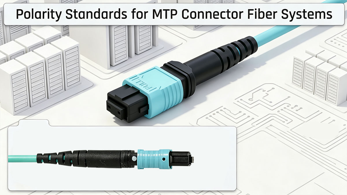
Κατανόηση της πολικότητας: Γιατί έχει σημασία η κατεύθυνση του καλωδίου
Η πολικότητα αναφέρεται στην κατευθυντική ροή φωτεινών σημάτων μέσω οπτικών ινών, διασφαλίζοντας ότι το σήμα μετάδοσης (TX) στο ένα άκρο συνδέεται με τον εξοπλισμό λήψης (RX) στο άλλο. Σε ένα σύστημα οπτικών ινών με σύνδεσμο MTP πολλαπλών ινών, η διαχείριση αυτής της ροής γίνεται πολύ πιο περίπλοκη επειδή δεκάδες ίνες είναι ομαδοποιημένες σε ένα μόνο περίβλημα. Εάν η κατεύθυνση του καλωδίου αναμειχθεί ή αντιστραφεί, τα φωτεινά σήματα θα χτυπήσουν σε λάθος θύρες, προκαλώντας διακοπή ολόκληρης της σύνδεσης επικοινωνίας.
Η καθιέρωση ενός συνεπούς, τυποποιημένου σχήματος πολικότητας σε όλο το κέντρο δεδομένων αποτρέπει αυτά τα δαπανηρά σφάλματα σύνδεσης κατά τις αναβαθμίσεις υλικού. Οι μηχανικοί δικτύων βασίζονται σε συγκεκριμένα βιομηχανικά πρότυπα, όπως το TIA-568, για να καθορίσουν τον τρόπο παρακολούθησης των μεμονωμένων κλώνων οπτικών ινών από άκρο σε άκρο. Ο σωστός σχεδιασμός πολικότητας διασφαλίζει ότι η προσθήκη νέων διακοπτών υψηλής ταχύτητας ή η μετεγκατάσταση σε υψηλότερα εύρη ζώνης παραμένει μια απλή διαδικασία plug-and-play.
Οι τρεις τυπικές μέθοδοι εγκατάστασης: Τύπος A, Τύπος B και Τύπος C
Για την απλοποίηση της δρομολόγησης πολλαπλών οπτικών ινών, ο κλάδος ορίζει τρεις διακριτές μεθόδους χαρτογράφησης, γνωστές ως Τύπος Α, Τύπος Β και Τύπος Γ. Ο Τύπος Α χρησιμοποιεί μια προσέγγιση straight-through χαρτογράφησης, που σημαίνει ότι η θέση 1 της οπτικής ίνας στον πρώτο σύνδεσμο φτάνει ακριβώς στη θέση 1 στον σύνδεσμο far-end. Αυτή η μέθοδος απαιτεί ένα μείγμα διαφορετικών στυλ καλωδίου patch σε κάθε άκρο της σύνδεσης για τη σωστή διασταύρωση των σημάτων μετάδοσης και λήψης.
Ο Τύπος Β χρησιμοποιεί ένα πλήρως ανεστραμμένο σχήμα χαρτογράφησης, όπου η θέση 1 της οπτικής ίνας συνδέεται απευθείας με τη θέση 12 στο αντίθετο άκρο, αντιστρέφοντας αυτόματα τις γραμμές μετάδοσης και λήψης. Αυτή η μέθοδος είναι ιδιαίτερα δημοφιλής για άμεσες συνδέσεις switch-to-switch χρησιμοποιώντας μια ραχοκοκαλιά οπτικής ίνας με σύνδεσμο MTP. Τέλος, ο Τύπος C χρησιμοποιεί μια προσέγγιση αναστροφής ζευγών, διασταυρώνοντας διαδοχικά ζεύγη οπτικών ινών (όπως 1-προς-2 και 2-προς-1) κατά μήκος της σύνδεσης, καθιστώντας την ιδανική για τυπικές αρχιτεκτονικές διπλής όψης.
Πώς να αντιστοιχίσετε σωστά τους συνδέσμους Key-Up και Key-Down
Κάθε σύνδεσμος οπτικής ίνας MTP διαθέτει ένα μικρό κλειδί προσανατολισμού στη μία πλευρά του περιβλήματός της για να καθορίζει τον τρόπο με τον οποίο συνδέεται ο σύνδεσμος σε έναν προσαρμογέα. Όταν το κλειδί είναι στραμμένο προς τα πάνω, αναφέρεται ως "Key-Up" και όταν είναι στραμμένο προς τα κάτω, ονομάζεται "Key-Down". Η σωστή αντιστοίχιση αυτών των κλειδιών στους προσαρμογείς σας επιτρέπει στα καλώδια Τύπου Α, Τύπου Β ή Τύπου C να επιτύχουν την συγκεκριμένη εσωτερική δρομολόγηση οπτικών ινών.
Οι τυπικές πρακτικές για την ευθυγράμμιση αυτών των φυσικών κλειδιών στους προσαρμογείς δικτύου σας περιγράφονται παρακάτω:
- Προσαρμογείς Τύπου Α: Χρησιμοποιήστε ευθυγράμμιση Key-Up προς Key-Down για να διατηρήσετε την ευθεία τοποθέτηση των ινών.
- Προσαρμογείς Τύπου Β: Χρησιμοποιήστε ευθυγράμμιση Key-Up με Key-Up για να αναστρέψετε πλήρως την τοποθέτηση της εσωτερικής ίνας.
- Η συνέπεια είναι το κλειδί: Ποτέ μην αναμειγνύετε διαφορετικούς τύπους προσαρμογέων στον ίδιο σύνδεσμο για να αποφύγετε την παρεμβολή του σήματος.
- Ελέγξτε τις οπτικές σημάνσεις: Αναζητήστε χυτευμένες ετικέτες ή χρωματικά κωδικοποιημένες κουκκίδες στο περίβλημα του προσαρμογέα για να επαληθεύσετε τον προσανατολισμό.
Απλές συμβουλές για να αποφύγετε τα συνηθισμένα λάθη πολικότητας
Ακόμα και έμπειροι τεχνικοί μπορούν να κάνουν λάθη κατά την ανάπτυξη σύνθετων συστοιχιών οπτικών ινών MTP σε ένα rack υψηλής πυκνότητας. Ένα μόνο λάθος καλώδιο patch μπορεί να διαταράξει την πολικότητα μιας ολόκληρης σειράς καμπινών, οδηγώντας σε κουραστική αντιμετώπιση προβλημάτων και διακοπή λειτουργίας του δικτύου. Η τήρηση ορισμένων αυστηρών κανόνων εγκατάστασης μπορεί να εξαλείψει εντελώς αυτούς τους κινδύνους προτού επηρεάσουν την ζωντανή σας κίνηση.
Η εφαρμογή αυτών των απλών βημάτων θα διατηρήσει το εργοστάσιο καλωδίων υψηλής πυκνότητας οργανωμένο και χωρίς σφάλματα:
- Μείνετε πιστοί σε ένα πρότυπο: Επιλέξτε είτε τον Τύπο Α, τον Τύπο Β ή τον Τύπο Γ και χρησιμοποιήστε τον σε ολόκληρο τον ιστότοπο.
- Χρησιμοποιήστε καλώδια με χρωματική κωδικοποίηση: Επισημάνετε τους διαφορετικούς τύπους καλωδίων με ξεχωριστά χρώματα περιβλήματος για εύκολη οπτική παρακολούθηση.
- Δοκιμή πριν από τη σύνδεση: Χρησιμοποιείτε πάντα έναν οπτικό εντοπιστή σφαλμάτων ή έναν ελεγκτή πολικότητας πριν από την τελική εγκατάσταση.
- Διατηρήστε την τεκμηρίωση ενημερωμένη: Ενημερώστε τους χάρτες patch δικτύου σας αμέσως κάθε φορά που μετακινείται ή προστίθεται ένα καλώδιο.
🍃 Επιλογή των σωστών ακίδων για σύνδεση οπτικών ινών MTP
Η επιλογή του σωστού φύλου σύνδεσης είναι ένα κρίσιμο βήμα κατά την ανάπτυξη μιας οπτικής υποδομής υψηλής πυκνότητας. Σε αντίθεση με τις παραδοσιακές συνδέσεις μονής ίνας, οι συνδέσεις πολλαπλών ινών βασίζονται σε ακριβείς φυσικές ακίδες για να διατηρούν τα εσωτερικά νήματα γυαλιού τέλεια ευθυγραμμισμένα. Η σωστή αυτή επιλογή αποτρέπει τον χρόνο διακοπής λειτουργίας του δικτύου και διασφαλίζει μια ασφαλή και μακροχρόνια εγκατάσταση υλικού.
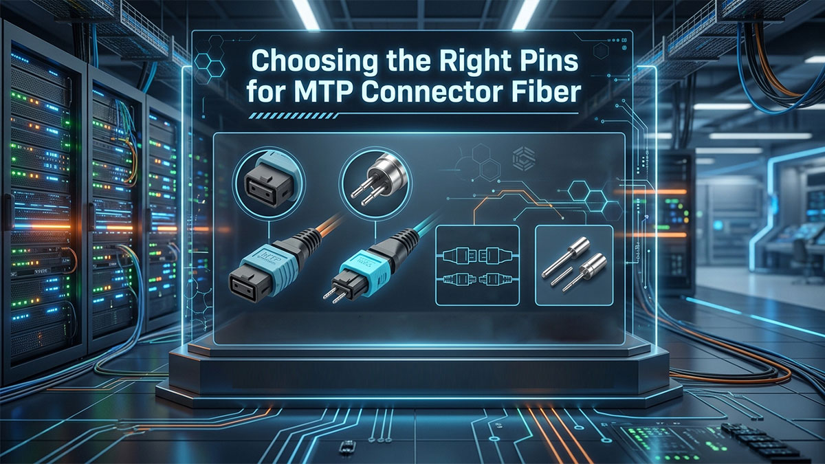
Επεξήγηση των καρφιτσωμένων (αρσενικών) έναντι των μη καρφιτσωμένων (θηλυκών) συνδέσμων
Κάθε διεπαφή οπτικής ίνας σύνδεσης MTP ταξινομείται είτε ως καρφιτσωμένη (αρσενική) είτε ως μη καρφιτσωμένη (θηλυκή) για να εξασφαλιστεί η σωστή φυσική σύνδεση. Οι καρφιτσωμένοι σύνδεσμοι διαθέτουν δύο μικροσκοπικούς, μεταλλικούς οδηγούς με ακρίβεια που προεξέχουν από το κέντρο της ακραίας επιφάνειας του κυλινδρικού ακροδέκτη. Αντίθετα, οι μη καρφιτσωμένοι σύνδεσμοι κατασκευάζονται με αντίστοιχες οπές οδηγούς σχεδιασμένες να δέχονται ακριβώς αυτούς τους ακροδέκτες κατά την εγκατάσταση.
Η κατανόηση αυτής της διάκρισης είναι ζωτικής σημασίας, επειδή δύο σύνδεσμοι του ίδιου φύλου δεν μπορούν να συνδυαστούν μεταξύ τους. Η προσπάθεια να συνδέσετε δύο συνδεδεμένα βύσματα μεταξύ τους θα σπάσει τους ευαίσθητους ακροδέκτες οδηγούς και θα συνθλίψει μόνιμα τις ίνες γυαλιού. Εν τω μεταξύ, η σύνδεση δύο μη συνδεδεμένων βυσμάτων μεταξύ τους έχει ως αποτέλεσμα μια ασταθή σύνδεση με τεράστια κενά, εμποδίζοντας εντελώς τη μετάδοση δεδομένων.
Πώς να συνδέσετε με ασφάλεια αρσενικά και θηλυκά εξαρτήματα
Η σύνδεση διεπαφών πολλαπλών ινών απαιτεί αυστηρή τήρηση των κανόνων φυσικής ασφάλειας για την αποφυγή πρόκλησης ζημιών στα εξαρτήματα ακριβείας. Επειδή οι εσωτερικές ίνες γυαλιού είναι ιδιαίτερα ευαίσθητες στην πίεση και την κακή ευθυγράμμιση, οι τεχνικοί πρέπει να χειρίζονται κάθε σύνδεση με εξαιρετική προσοχή. Η τήρηση μιας τυποποιημένης λίστας ελέγχου εγκατάστασης διασφαλίζει μια τέλεια σύνδεση χωρίς να διακινδυνεύσει βλάβη στο υλικό.
Για την ασφαλή σύνδεση αυτών των εξαρτημάτων σύνδεσης, πρέπει να ακολουθήσετε τα ακόλουθα βήματα:
- Επαλήθευση του Φύλου: Ελέγξτε και τις δύο άκρες του συνδετήρα για να βεβαιωθείτε ότι ενώνετε ένα καρφιτσωμένο και ένα ξεκαρφιτσωμένο άκρο.
- Επιθεωρήστε τις άκρες των πλευρών: Χρησιμοποιήστε ένα μικροσκόπιο οπτικών ινών για να ελέγξετε για σκόνη ή γρατσουνιές πριν τις συνδέσετε.
- Ευθυγραμμίστε τα πλήκτρα οδηγών: Αντιστοιχίστε σωστά τα πλήκτρα φυσικού προσανατολισμού στα περιβλήματα των συνδετήρων.
- Πιέστε μέχρι να κάνει κλικ: Εισάγετε τον σύνδεσμο κατευθείαν στον προσαρμογέα μέχρι να ακούσετε ένα σταθερό κλικ ασφάλισης.
- Αποφύγετε την υπερβολική άσκηση δύναμης: Σταματήστε αμέσως εάν αισθανθείτε αντίσταση, καθώς η άσκηση πίεσης στη σύνδεση μπορεί να θρυμματίσει το γυαλί.
Γιατί η ευθυγράμμιση των ακίδων έχει σημασία για ένα ισχυρό σήμα δικτύου
Σε ένα δίκτυο οπτικών ινών με σύνδεσμο MTP, οι ακίδες-οδηγοί είναι αποκλειστικά υπεύθυνοι για τη συγκράτηση και των 8, 12 ή 24 πυρήνων οπτικών ινών σε τέλεια ευθυγράμμιση. Επειδή κάθε μεμονωμένος πυρήνας οπτικής ίνας είναι μικροσκοπικός, ακόμη και μια μικρή μετατόπιση μερικών μικρομέτρων μπορεί να προκαλέσει σοβαρή διαρροή φωτός. Η σωστή ευθυγράμμιση διασφαλίζει ότι οι παλμοί φωτός ταξιδεύουν απρόσκοπτα από το ένα καλώδιο στο επόμενο χωρίς να αναπηδούν πίσω.
Εάν οι ακίδες οδηγοί είναι λυγισμένες, φθαρμένες ή χαλαρές, η προκύπτουσα κακή ευθυγράμμιση θα προκαλέσει μαζική εξασθένηση σήματος και υψηλή απώλεια εισαγωγής. Αυτό αποδυναμώνει το σήμα δικτύου, οδηγώντας σε απώλεια πακέτων δεδομένων, σφάλματα CRC και χαμηλές ταχύτητες δικτύου. Η χρήση υποδοχών υψηλής ποιότητας με ελλειπτικές ακίδες προστατεύει τις οπές οδηγών και εγγυάται μακροπρόθεσμη σταθερότητα σήματος.
Πρότυπα Επιλογής Φύλου για Συνδέσεις Πομποδέκτη έναντι Συνδέσεων Patch Panel
Ο καθορισμός του εάν θα αναπτύξετε συνδεδεμένα ή μη συνδεδεμένα καλώδια εξαρτάται αποκλειστικά από τις συγκεκριμένες διεπαφές υλικού που υπάρχουν στη διάταξη του δικτύου σας. Οι τυποποιημένοι οπτικοί πομποδέκτες και οι θύρες εξοπλισμού κατασκευάζονται με μια σταθερή εσωτερική διαμόρφωση που υπαγορεύει τις επιλογές καλωδίων σας. Τα σχέδια δικτύου πρέπει να ακολουθούν τους καθιερωμένους κανόνες αντιστοίχισης για να διατηρείται η συμβατότητα σε όλα τα σημεία σύνδεσης.
Οι τυπικές πρακτικές ανάπτυξης απαιτούν τις ακόλουθες επιλογές φύλου σε όλη την υποδομή σας:
- Θύρες Πομποδέκτη: Οι οπτικοί πομποδέκτες (όπως οι QSFP+ ή QSFP28) διαθέτουν πάντα εσωτερικές υποδοχές με ακίδες (αρσενικές).
- Καλώδια Patch: Τα καλώδια που συνδέονται απευθείας στους πομποδέκτες του εξοπλισμού πρέπει να είναι ξεκαρφιτσωμένα (θηλυκά) σε αυτό το άκρο.
- Καλώδια κορμού: Τα κύρια καλώδια κορμού που τρέχουν μεταξύ των πάνελ συνήθως διαθέτουν αρσενικούς συνδετήρες με ακίδες και στα δύο άκρα.
🍃 Πρότυπα Σχεδιασμού για Προϋπολογισμούς Απωλειών σε Συνδέσεις Οπτικών Ινών MTP
Ο ακριβής υπολογισμός ενός προϋπολογισμού οπτικών απωλειών αποτελεί θεμελιώδη απαίτηση κατά τη σχεδίαση ενός δικτύου κέντρων δεδομένων υψηλής απόδοσης. Κάθε σημείο σύνδεσης, σύνδεση και μετρητής καλωδίου εισάγει μια μικρή ποσότητα υποβάθμισης σήματος που μπορεί να απειλήσει τη συνολική σταθερότητα του δικτύου. Η καθιέρωση αυστηρών ορίων σχεδιασμού διασφαλίζει ότι τα δεδομένα που ταξιδεύουν μέσω μιας σύνδεσης οπτικών ινών MTP διατηρούν αρκετή ισχύ ώστε να διαβάζονται καθαρά από το υλικό λήψης.
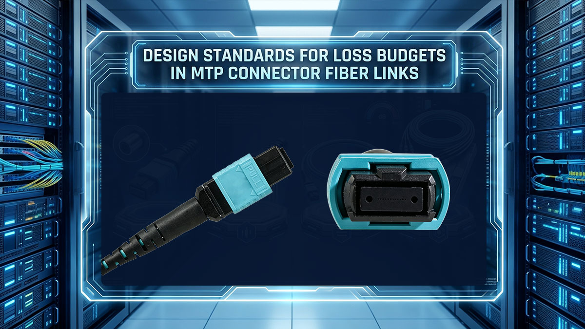
Πρότυπα TIA και ISO για αποδεκτή απώλεια σήματος οπτικών ινών
Οι φορείς που διέπουν τον κλάδο, όπως η TIA και ο ISO, έχουν θεσπίσει σαφή κριτήρια αξιολόγησης για τον καθορισμό της μέγιστης επιτρεπόμενης απώλειας σήματος για τα οπτικά εξαρτήματα. Για παράδειγμα, οι τυπικές προδιαγραφές TIA-568 ορίζουν ότι μια παραδοσιακή σύνδεση πολλαπλών οπτικών ινών δεν πρέπει να υπερβαίνει τη μέγιστη απώλεια των 0.75dB ανά συνδεδεμένο ζεύγος. Η τήρηση αυτών των τυποποιημένων κατευθυντήριων γραμμών παρέχει στους μηχανικούς δικτύων μια προβλέψιμη γραμμή αναφοράς για να διασφαλίσουν τη συμβατότητα υλικού πολλαπλών προμηθευτών.
Ωστόσο, καθώς τα δίκτυα μεταβαίνουν σε εξαιρετικά υψηλές ταχύτητες, αυτά τα παλαιά όρια απώλειας είναι συχνά πολύ υψηλά για να τα ανεχθούν οι σύγχρονοι πομποδέκτες. Τα πρότυπα ISO/IEC παρέχουν ενημερωμένες παραμέτρους που βοηθούν τους σχεδιαστές να υπολογίσουν τη συνολική εξασθένηση της σύνδεσης υπό αυστηρότερες συνθήκες λειτουργίας. Η τήρηση αυτών των διεθνών βασικών γραμμών αποτρέπει τα σφάλματα μετάδοσης και διατηρεί την οπτική υποδομή πλήρως συμβατή με τους παγκόσμιους κανόνες συμμόρφωσης.
Σχεδιασμός για Προϋπολογισμούς Χαμηλών Ζημιών έναντι Προϋπολογισμών Τυπικών Ζημιών
Τα εξαρτήματα τυπικής απώλειας είναι ευρέως διαθέσιμα και οικονομικά αποδοτικά, προσφέροντας συνήθως απώλεια εισαγωγής περίπου 0.5dB έως 0.75dB ανά σύνδεση οπτικής ίνας MTP. Ενώ αυτό είναι απολύτως αποδεκτό για μικρές αποστάσεις ή απλές συνδέσεις από σημείο σε σημείο, η απώλεια συσσωρεύεται γρήγορα όταν εισάγονται πολλαπλά πάνελ patch. Σε σύνθετες αρχιτεκτονικές, η αποκλειστική εξάρτηση από εξαρτήματα τυπικής απώλειας μπορεί εύκολα να εξαντλήσει ολόκληρο τον οπτικό σας προϋπολογισμό.
Για την αντιμετώπιση αυτού του προβλήματος, τα premium εξαρτήματα χαμηλών απωλειών μειώνουν τη μέγιστη απώλεια εισαγωγής σε 0.25dB ή 0.35dB ανά σύνδεση. Η αξιοποίηση αυτών των επιλογών υψηλής απόδοσης παρέχει στους σχεδιαστές δικτύων το απαραίτητο περιθώριο κατά την κατασκευή πολλαπλών σταδίων διασυνδέσεων. Η επένδυση σε τεχνολογία χαμηλών απωλειών διασφαλίζει ότι το οπτικό σήμα παραμένει αρκετά ισχυρό ώστε να υποστηρίζει μελλοντικές αναβαθμίσεις δικτύου χωρίς να χρειάζεται να ξαναγραφεί το φυσικό επίπεδο.
Πώς να υπολογίσετε τη συνολική επιτρεπόμενη απώλεια σε ένα κανάλι υψηλής πυκνότητας
Ο υπολογισμός του συνολικού προϋπολογισμού απωλειών ενός καναλιού απαιτεί την προσθήκη των μέγιστων τιμών εξασθένησης χειρότερης περίπτωσης κάθε μεμονωμένου στοιχείου κατά μήκος της διαδρομής της οπτικής ίνας. Ο βασικός τύπος συνδυάζει τη συνολική απώλεια του ακατέργαστου μήκους του καλωδίου οπτικής ίνας με την απώλεια εισαγωγής όλων των συνδεδεμένων ζευγών συνδετήρων και συνδέσεων. Οι σχεδιαστές πρέπει πάντα να χρησιμοποιούν τις μέγιστες βαθμολογίες απωλειών του κατασκευαστή αντί για ιδανικούς μέσους όρους για να διασφαλίσουν ότι το σύστημα λειτουργεί υπό πραγματικές συνθήκες.
Μόλις καθοριστεί η συνολική υπολογιζόμενη απώλεια, πρέπει να συγκριθεί με τον μέγιστο προϋπολογισμό ισχύος που υποστηρίζεται από τους συγκεκριμένους πομποδέκτες δικτύου σας. Αποτελεί συνήθη πρακτική να συμπεριλαμβάνεται ένα επιπλέον περιθώριο ασφαλείας από 0.5dB έως 1.0dB για να λαμβάνεται υπόψη η γήρανση των εξαρτημάτων και η απροσδόκητη περιβαλλοντική καταπόνηση. Εάν ο τελικός αριθμός ταιριάζει άνετα εντός των ορίων του πομποδέκτη, το κανάλι οπτικών ινών του συνδέσμου MTP θεωρείται ασφαλές για ανάπτυξη.
Τυπικά Όρια για Μέγιστους Κύκλους Ζευγαρώματος και Σημεία Σύνδεσης
Κάθε φορά που συνδέεται και αποσυνδέεται μια οπτική ίνα σύνδεσης MTP, παρατηρείται μικροσκοπική φθορά στις ακίδες ευθυγράμμισης και στις άκρες των φερρουάλ. Τα βιομηχανικά πρότυπα ορίζουν ότι οι υψηλής ποιότητας πολυοπτικές συνδέσεις συνήθως έχουν ονομαστική τιμή για μέγιστο αριθμό 500 κύκλων ζευγαρώματος πριν αρχίσει να υποβαθμίζεται η απόδοση. Η παρακολούθηση αυτών των κύκλων σύνδεσης εμποδίζει το φθαρμένο υλικό να εισάγει απρόβλεπτες πτώσεις σήματος σε δίκτυα ζωντανής παραγωγής.
Επιπλέον, οι σχεδιαστές δικτύων πρέπει να περιορίσουν τον συνολικό αριθμό των φυσικών σημείων σύνδεσης εντός ενός μόνο καναλιού για να διατηρήσουν χαμηλή τη σωρευτική απώλεια εισαγωγής. Ο διαχωρισμός ενός συνδέσμου κορμού σε πάρα πολλά ενδιάμεσα πάνελ patch μπορεί να διασκορπίσει γρήγορα το φωτεινό σήμα πέρα από τα όρια ανάκτησης. Η διατήρηση της διαδρομής όσο το δυνατόν πιο άμεσης και η αντικατάσταση των παλαιών καλωδίων patch βοηθά στη διατήρηση της μακροπρόθεσμης ακεραιότητας της υποδομής υψηλής πυκνότητας.
🍃 Πρότυπα διαχείρισης καλωδίων για σύνδεση οπτικών ινών MTP
Η εφαρμογή δομημένης διαχείρισης καλωδίων είναι ζωτικής σημασίας για τη διατήρηση της δομικής ακεραιότητας και της απόδοσης ενός οπτικού δικτύου υψηλής πυκνότητας. Επειδή τα συγκροτήματα πολλαπλών ινών φιλοξενούν πολυάριθμα ευαίσθητα γυάλινα νήματα, ο ακατάλληλος χειρισμός μπορεί εύκολα να οδηγήσει σε υποβάθμιση του σήματος ή φυσική θραύση. Η τήρηση των καθιερωμένων οργανωτικών προτύπων διασφαλίζει βέλτιστη ροή αέρα, ευκολότερη αντιμετώπιση προβλημάτων και μακροπρόθεσμη αξιοπιστία δικτύου.
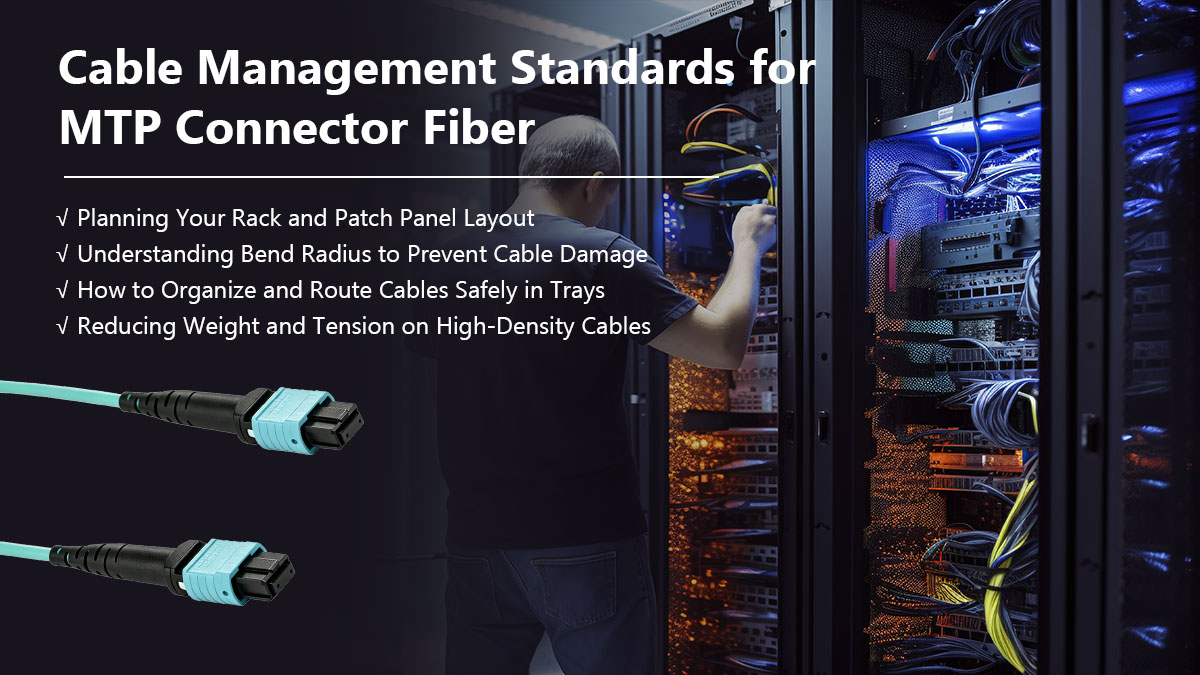
Σχεδιασμός της διάταξης του rack και του patch panel σας
Μια καλά μελετημένη διάταξη rack χρησιμεύει ως βάση για μια οργανωμένη και κλιμακώσιμη υποδομή οπτικών ινών σύνδεσης MTP. Η βέλτιστη πρακτική είναι να αφιερώνετε συγκεκριμένες μονάδες rack για πάνελ patch υψηλής πυκνότητας, διαχωρίζοντάς τες λογικά από τον ενεργό εξοπλισμό, όπως διακόπτες και διακομιστές. Αυτός ο στρατηγικός διαχωρισμός ελαχιστοποιεί τον κίνδυνο τυχαίων διακοπών καλωδίων όταν οι τεχνικοί εκτελούν συνήθη συντήρηση ή αναβαθμίσεις υλικού.
Επιπλέον, η ενσωμάτωση κάθετων και οριζόντιων διαχειριστών καλωδίων μέσα στο πλαίσιο του rack βοηθά στη διατήρηση της τακτοποιημένης ταξινόμησης των εισερχόμενων γραμμών του κεντρικού δικτύου. Η χρήση γωνιακών πάνελ patch μπορεί επίσης να είναι εξαιρετικά ωφέλιμη, καθώς καθοδηγούν φυσικά τα καλώδια patch προς τις πλευρικές διαδρομές χωρίς να προκαλούν στενές τσακίσεις. Ο σωστός σχεδιασμός της διάταξης εξοικονομεί τελικά πολύτιμο χώρο στο δάπεδο, ενώ παράλληλα καθιστά πολύ πιο εύκολη την πλοήγηση σε ολόκληρο το δίκτυο.
Κατανόηση της ακτίνας κάμψης για την πρόληψη ζημιών στο καλώδιο
Η ακτίνα κάμψης αναφέρεται στην ελάχιστη γωνία που ένα καλώδιο οπτικών ινών μπορεί να κάμψει με ασφάλεια χωρίς να προκαλέσει εσωτερική ζημιά στο γυαλί ή εξασθένηση του σήματος. Η υπέρβαση αυτού του ορίου προκαλεί μακροκάμψη, ένα πρόβλημα όπου οι παλμοί φωτός διαφεύγουν μέσω της επένδυσης αντί να ταξιδεύουν κατευθείαν κάτω από τον πυρήνα της οπτικής ίνας. Για ένα καλώδιο οπτικών ινών με σύνδεσμο MTP, η διατήρηση της σωστής ακτίνας κάμψης είναι ιδιαίτερα κρίσιμη, καθώς προστατεύει πολλαπλά νήματα ταυτόχρονα.
Τα βιομηχανικά πρότυπα συνήθως υπαγορεύουν ότι η δυναμική ακτίνα κάμψης ενός καλωδίου πολλαπλών ινών κατά την εγκατάσταση πρέπει να είναι τουλάχιστον 20 φορές η εξωτερική διάμετρος του καλωδίου. Μόλις το καλώδιο στερεωθεί στην τελική του θέση, η στατική ακτίνα κάμψης πρέπει να διατηρείται τουλάχιστον 10 φορές η διάμετρος. Η τήρηση αυτών των αυστηρών δομικών ορίων διατηρεί τα εσωτερικά φωτεινά σήματα ισχυρά και αποτρέπει τα μόνιμα μικρο-θραύσεις στο γυαλί.
Πώς να οργανώσετε και να δρομολογήσετε καλώδια με ασφάλεια σε δίσκους
Οι εναέριες και οι υποδαπέδιες σχάρες καλωδίων παρέχουν τις απαραίτητες οδούς για την ασφαλή δρομολόγηση μεγάλων όγκων γραμμών υψηλής πυκνότητας σε όλο το κέντρο δεδομένων. Χωρίς την κατάλληλη συγκράτηση, οι βαριές δέσμες καλωδίων μπορούν εύκολα να μπερδευτούν, καθιστώντας σχεδόν αδύνατη την μελλοντική αντιμετώπιση προβλημάτων. Η χρήση εξειδικευμένων διαχωριστικών και σωλήνων απόρριψης καλωδίων εντός των σχάρων διασφαλίζει την ομαλή μετάβαση στα rack εξοπλισμού.
Η τήρηση των ακόλουθων κανόνων δρομολόγησης θα διατηρήσει τα μονοπάτια υψηλής πυκνότητας καθαρά και ασφαλή:
- Ξεχωριστοί τύποι καλωδίων: Διατηρήστε τα καλώδια πολλαπλών ινών απομονωμένα από τα βαριά χάλκινα καλώδια δεδομένων.
- Αποφύγετε την υπερπλήρωση των δίσκων: Περιορίστε το συνολικό βάθος καλωδίου σε μέγιστο 50% χωρητικότητας.
- Χρησιμοποιήστε κουμπώματα με γάντζο και θηλιά: Ασφαλίστε τις δέσμες χρησιμοποιώντας μαλακούς ιμάντες Velcro αντί για σφιχτά φερμουάρ.
- Διατηρήστε ομαλές στροφές: Χρησιμοποιήστε σαρωτικές καμπύλες συνδέσεις αντί για αιχμηρές γωνίες 90 μοιρών.
- Επισημάνετε κάθε δέσμη: Εφαρμόστε σαφείς, ευανάγνωστες ετικέτες αναγνώρισης και στα δύο άκρα της διαδρομής του δίσκου.
Μείωση βάρους και τάσης σε καλώδια υψηλής πυκνότητας
Το συσσωρευμένο βάρος αποτελεί σημαντική ανησυχία κατά τη σύνδεση πολλαπλών γραμμών πολλαπλών ινών σε περιβάλλον υψηλής πυκνότητας. Η υπερβολική τάση έλξης κατά την εγκατάσταση ή οι βαριές, μη υποστηριζόμενες θηλιές ανάρτησης μπορούν να ασκήσουν σοβαρή πίεση στα περιβλήματα των συνδετήρων. Αυτή η φυσική καταπόνηση μπορεί να προκαλέσει την απομάκρυνση των ευαίσθητων εσωτερικών ινών γυαλιού από το δαχτυλίδι, με αποτέλεσμα την άμεση αστοχία της σύνδεσης.
Για τον μετριασμό αυτού του κινδύνου, οι εγκαταστάτες δικτύων πρέπει να χρησιμοποιούν προστατευτικά ασφαλείας και να ασφαλίζουν τα καλώδια σε ενδιάμεσα σημεία αγκύρωσης κατά μήκος του πλαισίου του rack. Η παροχή επαρκών βρόχων χαλάρωσης διασφαλίζει ότι το βάρος των κάθετων καλωδίων κατανέμεται ομοιόμορφα αντί να τραβάει απευθείας τις ενεργές θύρες. Η ελαχιστοποίηση της μηχανικής τάσης προστατεύει την ακριβή ευθυγράμμιση των συνδέσεων οπτικών ινών του συνδέσμου MTP, εγγυώμενη σταθερή μακροπρόθεσμη απόδοση δικτύου.
🍃 Πρότυπα καθαρισμού και δοκιμών για οπτικές ίνες σύνδεσης MTP
Η διατήρηση απόλυτης καθαριότητας και η διεξαγωγή αυστηρών δοκιμών είναι τα τελικά, αδιαπραγμάτευτα βήματα σε κάθε επιτυχημένη ανάπτυξη υψηλής πυκνότητας. Επειδή οι οπτικές ίνες μεταδίδουν δεδομένα χρησιμοποιώντας φως, ακόμη και μια μικροσκοπική κηλίδα σκόνης μπορεί να υποβαθμίσει μόνιμα την απόδοση του σήματος ή να προκαλέσει ζημιά σε ακριβό υλικό. Η τήρηση αυστηρών προτύπων επιθεώρησης διασφαλίζει ότι η υποδομή δικτύου σας λειτουργεί στο μέγιστο των δυνατοτήτων της από την πρώτη κιόλας ημέρα.

Γιατί η καθαριότητα είναι κρίσιμη για τις συνδέσεις πολλαπλών ινών
Σε ένα σύστημα οπτικών ινών σύνδεσης MTP, πολλαπλοί πυρήνες γυαλιού είναι σφιχτά συσκευασμένοι μεταξύ τους σε μια ενιαία, συμπαγή επιφάνεια φερρουλίου. Αυτή η διάταξη υψηλής πυκνότητας σημαίνει ότι ένα μόνο χαλαρό σωματίδιο μπορεί εύκολα να μετακινηθεί κατά μήκος της επιφάνειας του φερρουλίου και να εμποδίσει πολλά κανάλια δεδομένων ταυτόχρονα. Επιπλέον, όταν οι μολυσμένοι σύνδεσμοι συνδέονται, η τεράστια φυσική πίεση μπορεί να αλέσει μόνιμα σωματίδια σκόνης στο γυαλί, προκαλώντας μόνιμες γρατσουνιές.
Σε αντίθεση με τις συνδέσεις μίας ίνας, οι διεπαφές πολλαπλών ινών είναι ιδιαίτερα ευάλωτες σε κενά αέρα που προκαλούνται από την ανομοιόμορφη μόλυνση στην επιφάνεια του φερρουλ. Μια μικροσκοπική κηλίδα λαδιού ή σκόνης στη μία πλευρά μπορεί να γείρει ελαφρώς ολόκληρο τον σύνδεσμο, διακόπτοντας τη φυσική επαφή για τις υπόλοιπες ίνες. Η διατήρηση αυτών των σημείων επαφής σε άψογη κατάσταση είναι απολύτως ζωτικής σημασίας για την αποφυγή υψηλής απώλειας εισαγωγής και καταστροφικής ανάκλασης.
Οδηγός βήμα προς βήμα για τον ασφαλή καθαρισμό των άκρων των ινών
Ο καθαρισμός των διεπαφών πολλαπλών ινών απαιτεί μια εξειδικευμένη προσέγγιση για την αποφυγή της εξάπλωσης ρύπων στους πολλαπλούς πυρήνες γυαλιού. Οι τεχνικοί δεν πρέπει ποτέ να χρησιμοποιούν στεγνά, μη εγκεκριμένα υλικά ή τραχιά υφάσματα που θα μπορούσαν εύκολα να γρατσουνίσουν τις γυαλισμένες με ακρίβεια επιφάνειες. Η τήρηση μιας τυποποιημένης, πειθαρχημένης διαδικασίας καθαρισμού εγγυάται βέλτιστη οπτική διαύγεια χωρίς να διακινδυνεύσει η φυσική ζημιά στα εξαρτήματα.
Τα ακόλουθα βήματα περιγράφουν την τυπική διαδικασία για τον ασφαλή καθαρισμό αυτών των διεπαφών πολλαπλών ινών:
- Επιθεώρηση πρώτα: Χρησιμοποιείτε πάντα ένα οπτικό σκόπευτρο για να δείτε το δαχτυλίδι πριν από την εφαρμογή οποιωνδήποτε εργαλείων καθαρισμού.
- Χρησιμοποιήστε ένα Click Cleaner: Τοποθετήστε ένα εξειδικευμένο εργαλείο MTP για καθαρισμό με κλικ απευθείας στο περίβλημα του συνδέσμου.
- Πιέστε για να κάνετε κλικ: Πιέστε σταθερά το εργαλείο μέχρι να ακούσετε ένα ακουστικό κλικ για να προωθήσετε την ταινία καθαρισμού.
- Δοκιμάστε το υγρό σε στεγνό καθάρισμα: Χρησιμοποιήστε ένα εγκεκριμένο μαντηλάκι οπτικών ινών με μια σταγόνα εξειδικευμένου διαλύτη για επίμονα υπολείμματα.
- Επανεξέταση της επιφάνειας: Ελέγξτε ξανά την τελική επιφάνεια στο μικροσκόπιο για να βεβαιωθείτε ότι έχουν εξαφανιστεί όλες οι μολύνσεις.
- Μην αγγίζετε ποτέ την άκρη: Αποφύγετε να αγγίζετε το καθαρισμένο δαχτυλίδι με τα δάχτυλά σας ή να το αφήνετε να χτυπήσει σε επιφάνειες.
Βασικά εργαλεία που απαιτούνται για δοκιμές και επιθεώρηση οπτικών ινών
Για την ορθή επικύρωση μιας εγκατάστασης οπτικής ίνας MTP, οι τεχνικοί πρέπει να είναι εξοπλισμένοι με ένα συγκεκριμένο σύνολο οπτικών οργάνων δοκιμών. Το πιο βασικό εργαλείο είναι ένας αισθητήρας επιθεώρησης βίντεο υψηλής ανάλυσης που έχει σχεδιαστεί ειδικά για πολλαπλές οπτικές ίνες, επιτρέποντας την ασφαλή προβολή όλων των πυρήνων ταυτόχρονα. Χωρίς αυτό το εργαλείο οπτικής επικύρωσης, οι τεχνικοί ουσιαστικά εργάζονται στα τυφλά και διακινδυνεύουν άμεση μόλυνση του δικτύου.
Για τον έλεγχο απόδοσης, απαιτείται ένα Σετ Δοκιμών Οπτικών Απωλειών (OLTS) ή ένα Πολυϊνικό Ανακλασόμετρο Οπτικού Χρονικού Πεδίου (OTDR) για τη μέτρηση της συνολικής απώλειας εισαγωγής και τον εντοπισμό ελαττωμάτων. Αυτοί οι προηγμένοι μετρητές διασφαλίζουν ότι η συνολική διαδρομή καλωδίου εμπίπτει με ασφάλεια εντός του προκαθορισμένου προϋπολογισμού απώλειας σύνδεσης. Η ύπαρξη των κατάλληλων εργαλείων βελτιστοποιεί τη διαδικασία πιστοποίησης και παρέχει επαληθεύσιμη απόδειξη ενός υγιούς δικτύου.
🍃 Βασικά σημεία για την εφαρμογή οπτικών ινών σύνδεσης MTP σε καλωδίωση υψηλής πυκνότητας
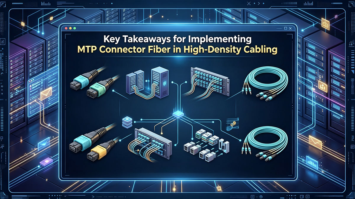
Η επιτυχής ανάπτυξη ενός συστήματος οπτικών ινών με σύνδεσμο MTP απαιτεί ιδιαίτερη προσοχή στη λεπτομέρεια σε κάθε στάδιο του σχεδιασμού του δικτύου σας. Κατακτώντας τα πρότυπα πολικότητας, επιλέγοντας τα σωστά φύλα των ακίδων και υπολογίζοντας με ακρίβεια τον προϋπολογισμό απωλειών, μπορείτε να αποφύγετε συνήθεις παγίδες εγκατάστασης και να εξαλείψετε τον απροσδόκητο χρόνο διακοπής λειτουργίας. Ο συνδυασμός της δομημένης διαχείρισης καλωδίων με αυστηρές συνήθειες καθαρισμού και δοκιμών διασφαλίζει ότι η υποδομή υψηλής πυκνότητας παραμένει αξιόπιστη και πλήρως βελτιστοποιημένη για μελλοντικές τεχνολογικές μεταβάσεις.
Η δημιουργία ενός άψογου φυσικού επιπέδου είναι μόνο η μισή μάχη. Ο συνδυασμός του με το σωστό ενεργό υλικό είναι αυτό που πραγματικά ζωντανεύει το κέντρο δεδομένων σας. Τα δίκτυα οπτικών ινών υψηλής πυκνότητας απαιτούν οπτικούς πομποδέκτες κορυφαίας ποιότητας που παρέχουν σταθερή απόδοση υπό μεγάλους φόρτους εργασίας. Επισκεφθείτε το LINK-PP Επίσημο κατάστημα σήμερα για να εξερευνήσετε την κορυφαία γκάμα μονάδων οπτικών πομποδεκτών μας, σχεδιασμένες να ενσωματώνονται άψογα με την αρχιτεκτονική οπτικών ινών υψηλής πυκνότητας που διαθέτετε.







