

































As data center traffic continues to grow rapidly due to cloud computing, artificial intelligence, and large-scale data processing, network infrastructures are increasingly transitioning from 100Gbps to 400Gbps Ethernet. To support these higher bandwidth requirements, several 400G optical interface standards have been developed, each optimized for different transmission distances and fiber infrastructures. Among them, 400GBASE FR4 has become one of the most widely adopted solutions for medium-reach single-mode fiber links.
400GBASE FR4 is designed to deliver 400Gbps Ethernet connectivity over duplex single-mode fiber with a reach of up to 2km. By combining four CWDM wavelengths with PAM4 modulation, it enables high-capacity data transmission while keeping fiber usage efficient. This architecture allows network operators to achieve high throughput without relying on large parallel fiber bundles, making it particularly suitable for modern data center and campus backbone networks.
Today, 400GBASE FR4 optical modules are commonly implemented in high-density form factors such as QSFP-DD and OSFP, enabling scalable deployment in hyperscale data centers, cloud infrastructure, and enterprise core networks. Their balance between transmission distance, fiber efficiency, and port density has made them an important component in the evolution of high-speed Ethernet.
This article explains what 400GBASE FR4 is, how its CWDM4 architecture works, its key technical specifications, and how it compares with other 400G optical standards. It also explores common deployment scenarios and practical considerations when designing 400G network links.
? What Is 400GBASE FR4?
400GBASE FR4 is a 400Gbps Ethernet optical interface standard designed for transmission over duplex single-mode fiber (SMF) with a reach of up to 2km. It uses four CWDM wavelengths and PAM4 modulation, allowing four optical lanes to each carry 100Gbps of data. This architecture enables high-capacity transmission while keeping fiber usage efficient, making FR4 suitable for data center interconnects and campus backbone networks.
Unlike parallel optical standards that require multiple fiber pairs, 400GBASE FR4 transmits all traffic through a single pair of fibers with wavelength multiplexing. This design significantly reduces cabling complexity and allows high-density deployment in modern switches and routers.
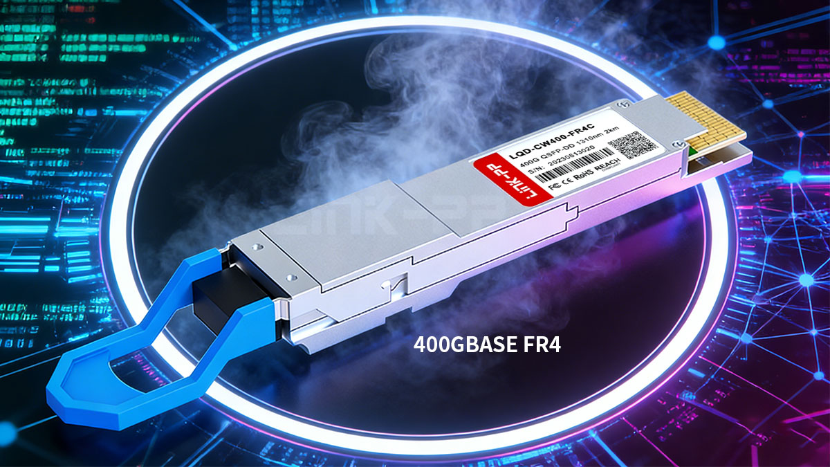
Definition of 400GBASE FR4
400GBASE FR4 refers to a 400GbE optical interface defined by the IEEE 802.3bs Ethernet standard. It specifies the physical layer technology used to transmit 400Gbps Ethernet signals across single-mode fiber links using wavelength division multiplexing.
The core characteristics of the standard include:
- Total data rate: 400Gbps Ethernet
- Optical lanes: 4 wavelengths
- Per-lane speed: 100Gbps using PAM4
- Fiber type: duplex single-mode fiber (OS2 fiber)
- Maximum reach: 2km
- Typical connector: LC duplex
The following table summarizes the essential parameters of the FR4 optical interface.
| Parameter | 400GBASE FR4 Specification |
|---|---|
| Data Rate | 400Gbps |
| Optical Lanes | 4 × 100Gbps |
| Fiber Type | Duplex Single-Mode Fiber |
| Maximum Distance | 2km |
Because FR4 uses wavelength multiplexing instead of parallel fibers, it can deliver high bandwidth while maintaining compatibility with standard single-mode fiber infrastructure.
Meaning of the FR4 Naming Convention
The name 400GBASE FR4 follows the standard Ethernet optical interface naming convention, where each part describes the technology and reach characteristics.
| Term | Meaning |
|---|---|
| 400G | 400 Gigabit Ethernet data rate |
| BASE | Baseband signaling over fiber |
| FR | Fiber reach category |
| 4 | Four optical transmission lanes |
In practical terms, the “4” indicates that four optical wavelengths are used, with each lane transmitting 100Gbps. These wavelengths are multiplexed into a single fiber pair using CWDM technology, allowing the system to achieve a combined throughput of 400Gbps.
This naming convention also helps differentiate FR4 from other 400G standards such as DR4, SR8, and LR4, which use different optical architectures and transmission distances.
Typical Transmission Distance
400GBASE FR4 is designed for medium-reach optical links, supporting transmission distances of up to 2km over single-mode fiber. This reach range fills the gap between short-reach parallel optics and long-distance telecom-oriented modules.
The following table highlights typical deployment distances compared with other common 400G standards.
| Standard | Maximum Distance | Fiber Type |
|---|---|---|
| 400GBASE SR8 | 100m | Multimode Fiber |
| 400GBASE DR4 | 500m | Single-Mode Fiber |
| 400GBASE FR4 | 2km | Single-Mode Fiber |
| 400GBASE LR4 | 10km | Single-Mode Fiber |
Because of its 2km reach and duplex fiber design, FR4 is frequently used in scenarios such as:
- Data center interconnects between buildings
- Spine layer aggregation links
- Large campus network backbones
- Cloud infrastructure networks
This balance between reach, fiber efficiency, and high bandwidth has made 400GBASE FR4 one of the most practical 400G optical standards for modern Ethernet deployments.
? Technical Specifications of 400GBASE FR4
400GBASE QSFP-DD FR4 achieves 400Gbps Ethernet transmission over duplex single-mode fiber by combining four CWDM wavelengths with PAM4 modulation. Each optical lane carries 100Gbps, and wavelength multiplexing allows all four channels to travel through a single fiber pair. This design provides a balance between transmission reach, fiber efficiency, and deployment flexibility.
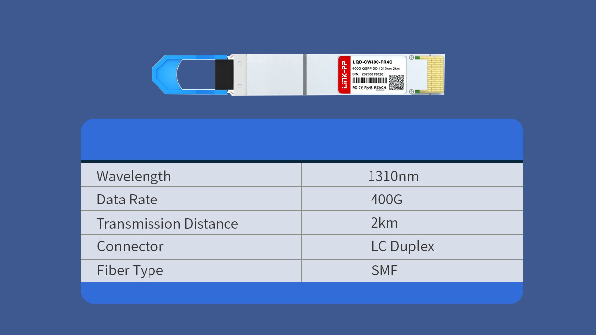
Understanding the technical specifications of FR4 is important for evaluating compatibility with switches, fiber infrastructure, and other 400G optical standards.
Optical Lane Architecture
The core architecture of 400GBASE FR4 is based on four optical lanes operating at 100Gbps each, which together deliver an aggregated bandwidth of 400Gbps. To achieve this rate efficiently, the standard uses PAM4 signaling, which allows higher data throughput without requiring proportional increases in bandwidth.
| Parameter | Specification |
|---|---|
| Total Ethernet Rate | 400Gbps |
| Optical Lanes | 4 |
| Per-Lane Data Rate | 100Gbps |
| Modulation | PAM4 |
Because each optical lane carries 100Gbps, the system can transmit large volumes of data while maintaining manageable optical component complexity. This architecture also enables high-density integration within modern pluggable transceiver modules.
CWDM4 Wavelength Plan
400GBASE FR4 uses coarse wavelength division multiplexing (CWDM) to transmit four optical channels over a duplex fiber pair. Each lane operates at a distinct wavelength, allowing the signals to be combined and transmitted simultaneously.
| Optical Lane | Center Wavelength |
|---|---|
| Lane 1 | 1271nm |
| Lane 2 | 1291nm |
| Lane 3 | 1311nm |
| Lane 4 | 1331nm |
The wavelengths are spaced roughly 20nm apart, which is characteristic of CWDM technology. This wider spacing simplifies laser design and reduces temperature sensitivity compared with denser wavelength systems.
Inside the optical module, an optical multiplexer combines the four wavelengths, while a corresponding demultiplexer separates them at the receiving end. This approach allows high-speed transmission while maintaining compatibility with standard single-mode fiber infrastructure.
Electrical Interface Inside the Module
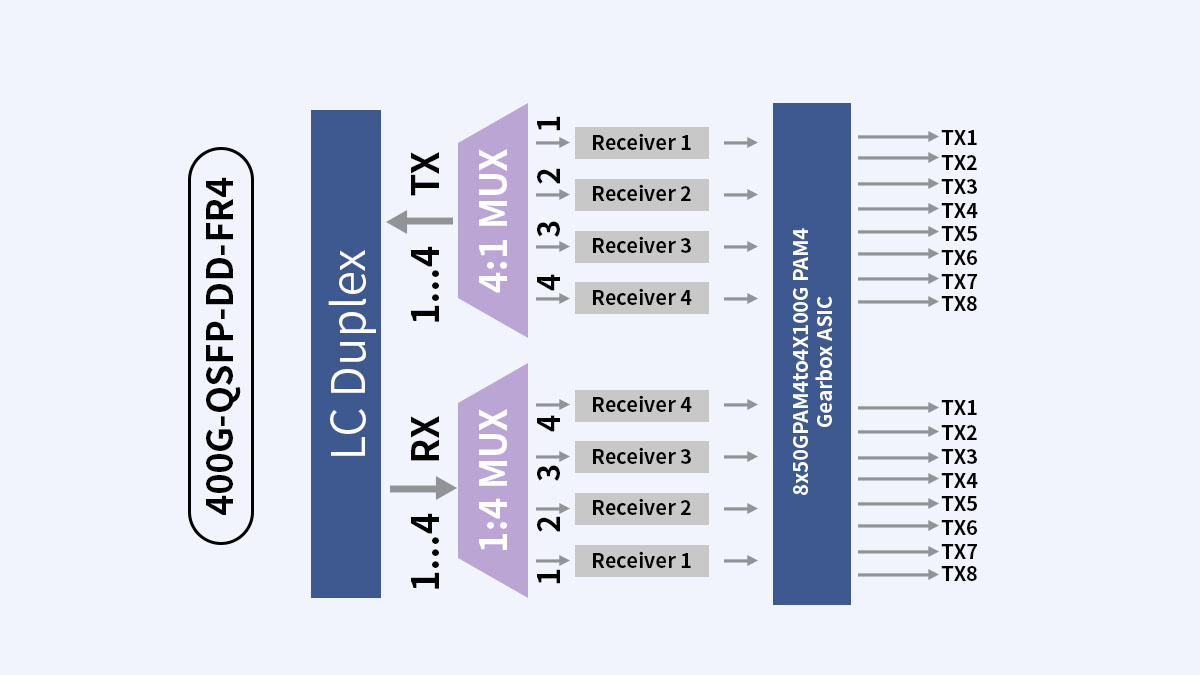
Inside a 400G FR4 transceiver, the electrical interface between the host device and the optical components typically operates using eight 50Gbps PAM4 electrical lanes. These signals are then converted into four 100Gbps optical lanes.
| Interface Type | Lane Configuration |
|---|---|
| Host Electrical Interface | 8 × 50Gbps PAM4 |
| Optical Interface | 4 × 100Gbps PAM4 |
| Signal Processing | Gearbox or DSP |
A gearbox or digital signal processor (DSP) is used to map the eight electrical lanes into four optical channels. This signal processing stage also performs functions such as equalization, error correction, and signal conditioning to maintain transmission quality.
This internal architecture allows modern switches to interface with high-speed optics while maintaining signal integrity across the optical link. It also supports the integration of FR4 technology into high-density form factors such as QSFP-DD and OSFP used in 400G optics platforms.
? How 400GBASE FR4 Works
400G QSFP-DD FR4 transmits 400Gbps Ethernet data over duplex single-mode fiber by combining PAM4 modulation with CWDM wavelength multiplexing. Inside the optical module, high-speed electrical signals from the switch are converted into four optical channels, each operating at 100Gbps. These four wavelengths are then multiplexed into a single fiber pair and transmitted simultaneously.
At the receiving end, the process is reversed: the incoming optical signal is demultiplexed into four wavelengths, converted back into electrical signals, and reassembled into the original data stream. This architecture allows high-speed transmission while minimizing the number of fibers required.
Role of PAM4 Modulation
PAM4 (Pulse Amplitude Modulation with four signal levels) is a key technology that enables 400G optical transmission without requiring extremely high symbol rates.
| Modulation Type | Bits per Symbol | Typical Use |
|---|---|---|
| NRZ | 1 | Legacy 10G / 25G Ethernet |
| PAM4 | 2 | 50G, 100G, 200G, and 400G Ethernet |
Because PAM4 encodes two bits per symbol instead of one, it effectively doubles the amount of data transmitted within the same bandwidth. This allows each optical lane in 400GBASE FR4 to carry 100Gbps of data, making it possible to achieve 400Gbps with only four wavelengths.
However, PAM4 signals are more sensitive to noise and distortion than NRZ signals. For this reason, modern optical modules use digital signal processing and forward error correction (FEC) to maintain signal integrity during transmission.
CWDM Multiplexing Technology
To transmit multiple high-speed channels over a single fiber pair, 400GBASE FR4 relies on coarse wavelength division multiplexing (CWDM).
CWDM allows different wavelengths of light to carry separate data streams simultaneously. In the FR4 architecture, four wavelengths are generated by independent lasers and then combined before transmission.
| Optical Function | Description |
|---|---|
| Laser Array | Generates four CWDM wavelengths |
| Optical Multiplexer | Combines wavelengths into one fiber |
| Optical Demultiplexer | Separates wavelengths at the receiver |
This multiplexing technique significantly improves fiber efficiency, because multiple data channels share the same physical fiber infrastructure. Instead of requiring multiple parallel fibers, the system can transmit all traffic through a duplex fiber pair.
CWDM is particularly suitable for data center environments because its wide wavelength spacing simplifies optical design and reduces temperature sensitivity.
Internal Components of a 400GBASE FR4 Module
A 400GBASE FR4 optical transceiver integrates several key components that enable high-speed optical communication. These elements work together to convert electrical data into multiplexed optical signals and then back into electrical form at the receiver.
| Component | Function |
|---|---|
| CWDM Laser Array | Generates four optical wavelengths |
| Optical Multiplexer/Demultiplexer | Combines and separates wavelengths |
| DSP or Gearbox | Performs signal conversion and equalization |
| Photodetector Array | Converts optical signals back to electrical signals |
The DSP or gearbox plays a critical role in maintaining signal quality by performing tasks such as lane mapping, equalization, and error correction. Meanwhile, thermal management systems ensure that the optical components remain stable during high-speed operation.
By integrating these technologies into compact pluggable form factors such as QSFP-DD or OSFP, 400GBASE FR4 modules can deliver high bandwidth while maintaining compatibility with modern data center switch platforms.
? 400GBASE FR4 vs Other 400G Optical Standards
Different 400G optical standards are designed for specific transmission distances, fiber infrastructures, and deployment scenarios. QDD 400G FR4 is optimized for medium-reach links up to 2km using duplex single-mode fiber, while other standards such as SR8, DR4, and LR4 target shorter or longer distances.
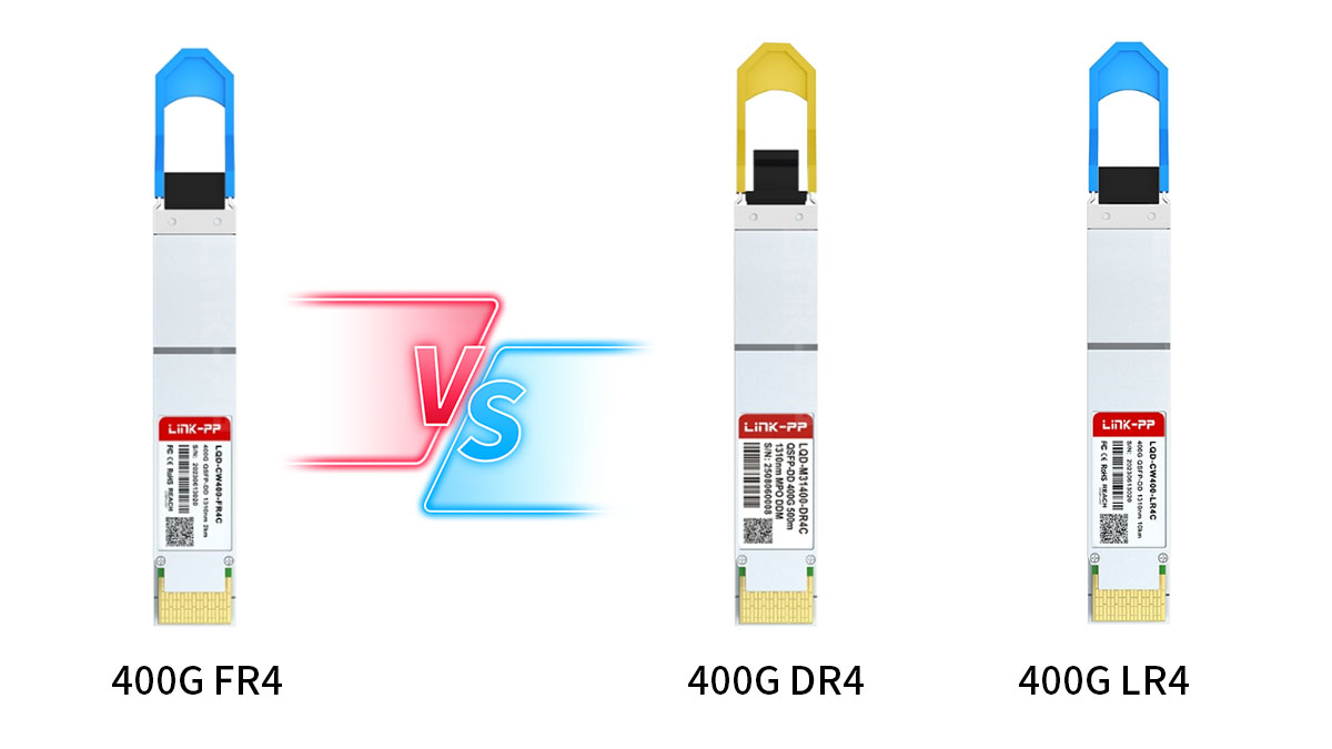
Understanding these differences helps network architects choose the most appropriate 400G optical technology for their infrastructure and performance requirements.
400GBASE FR4 vs 400GBASE DR4
The key difference between FR4 and DR4 lies in how the optical signals are transmitted and how many fibers are required. FR4 uses wavelength multiplexing over a duplex fiber pair, while DR4 uses parallel optical lanes across multiple fibers.
| Parameter | 400GBASE FR4 | 400GBASE DR4 |
|---|---|---|
| Transmission Distance | 2km | 500m |
| Fiber Type | Single-mode fiber | Single-mode fiber |
| Fiber Count | 2 fibers (duplex) | 8 fibers (4 pairs) |
| Optical Technology | CWDM | Parallel optics |
Because DR4 transceiver relies on parallel fibers, it is commonly used in short-reach data center connections, particularly in spine-leaf architecture where fiber ribbon cables are already deployed.
In contrast, FR4 requires only two fibers, which simplifies cabling and allows it to support longer links between buildings or across large campus networks.
400GBASE FR4 vs 400GBASE LR4
FR4 and LR4 both use wavelength division multiplexing over duplex single-mode fiber, but they differ primarily in transmission distance and optical design complexity.
| Parameter | 400GBASE FR4 | 400GBASE LR4 |
|---|---|---|
| Maximum Distance | 2km | 10km |
| Fiber Type | Single-mode fiber | Single-mode fiber |
| Wavelength Technology | CWDM | WDM |
| Typical Application | Data centers | Metro and campus links |
400G LR4 is designed for longer-distance transmission, which requires more advanced optical components and tighter wavelength control. As a result, LR4 solutions are typically used for campus backbone or metro network connections where links exceed the 2km reach of FR4.
FR4, on the other hand, focuses on efficient medium-range connectivity, making it well suited for large-scale data center networks.
Comparison of Major 400G Optical Standards
Several optical standards exist within the 400GbE ecosystem, each addressing different deployment requirements. The table below summarizes their key characteristics.
| Standard | Distance | Fiber Type | Connector |
|---|---|---|---|
| 400GBASE SR8 | 100m | Multimode fiber | MPO |
| 400GBASE DR4 | 500m | Single-mode fiber | MPO |
| 400GBASE FR4 | 2km | Single-mode fiber | LC |
| 400GBASE LR4 | 10km | Single-mode fiber | LC |
These standards form a hierarchy of reach and fiber infrastructure options:
- SR8 is optimized for short multimode links inside data centers.
- DR4 optics supports longer single-mode connections but requires parallel fibers.
- FR4 balances reach and fiber efficiency using CWDM multiplexing.
- LR4 extends transmission to longer campus or metro distances.
By selecting the appropriate optical standard, network designers can optimize both performance and infrastructure compatibility when deploying 400G Ethernet networks.
? Advantages of 400GBASE FR4
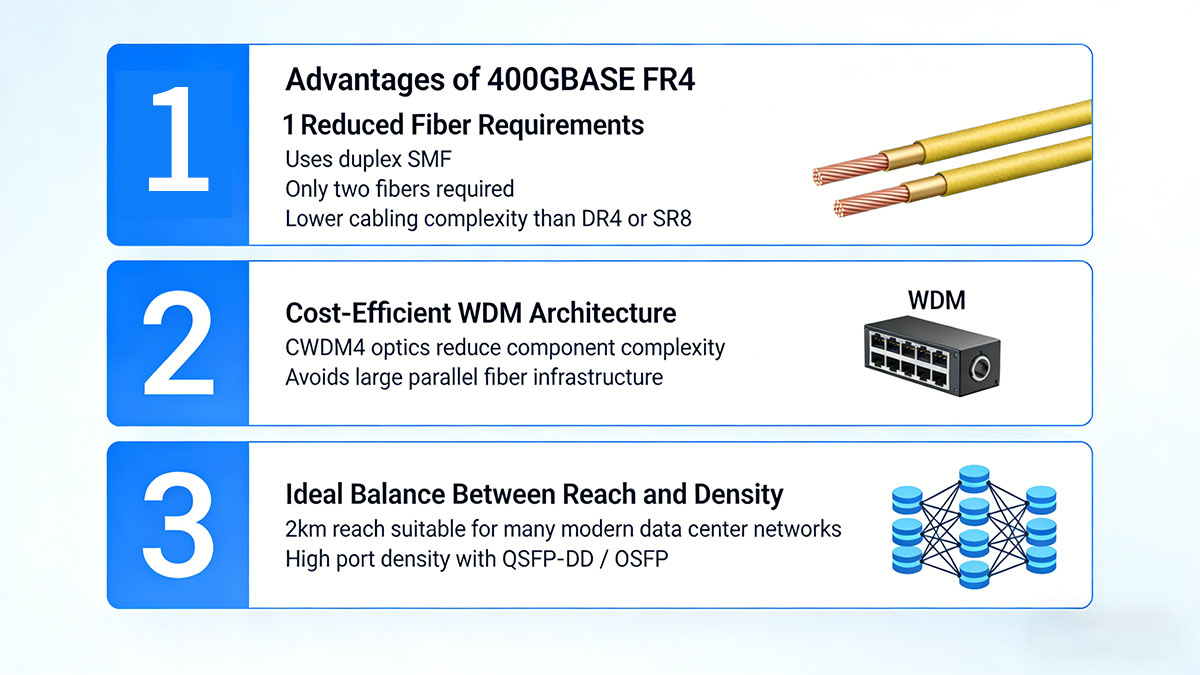
400GBASE FR4 offers a practical balance between high bandwidth, fiber efficiency, and medium transmission distance. By combining PAM4 modulation with CWDM multiplexing over duplex single-mode fiber, it allows network operators to deploy 400GbE links without requiring complex parallel fiber infrastructures.
These characteristics make FR4 particularly suitable for modern data centers, cloud infrastructure, and campus backbone networks.
Reduced Fiber Requirements
One of the most significant advantages of FR4 optics is its efficient use of fiber resources. Instead of relying on multiple parallel fibers, the technology transmits all four optical channels through a single duplex fiber pair.
| Standard | Fiber Count | Connector Type |
|---|---|---|
| 400GBASE DR4 | 8 fibers | MPO |
| 400GBASE SR8 | 16 fibers | MPO |
| 400GBASE FR4 | 2 fibers | LC |
Because FR4 requires only two fibers, it simplifies cabling design and reduces the need for high-density MPO fiber trunks. This can be particularly beneficial in environments where fiber infrastructure is limited or where upgrading existing cabling would be costly.
As a result, many networks can deploy 400GbE connectivity while continuing to use standard duplex single-mode fiber links.
Cost-Efficient WDM Architecture
Another advantage of FR4 is the use of CWDM wavelength multiplexing, which provides a simpler optical architecture compared with denser wavelength technologies.
| Feature | CWDM-Based Design | Parallel Optics |
|---|---|---|
| Fiber Utilization | High | Moderate |
| Optical Component Complexity | Moderate | Lower |
| Cabling Requirements | Minimal | Higher |
CWDM wavelengths are spaced relatively far apart, which simplifies laser design and thermal control. This allows FR4 modules to deliver high transmission speeds while maintaining manageable optical component complexity.
At the same time, wavelength multiplexing ensures that multiple data channels can share the same fiber pair, improving the overall efficiency of network infrastructure.
Ideal Balance Between Reach and Density
400GBASE FR4 is designed to support medium-range optical links up to 2km, filling an important gap between short-reach and long-distance 400G standards.
| Optical Standard | Maximum Reach | Typical Deployment |
|---|---|---|
| 400GBASE SR8 | 100m | Inside data centers |
| 400GBASE DR4 | 500m | Data center inter-rack links |
| 400GBASE FR4 | 2km | Inter-building data center links |
| 400GBASE LR4 | 10km | Campus and metro networks |
This 2km reach allows FR4 to support a wide range of scenarios such as inter-building data center connections, campus aggregation networks, and large-scale cloud infrastructure.
In addition, FR4 modules are widely available in high-density pluggable form factors such as QSFP-DD and OSFP, enabling network operators to deploy hundreds of 400G ports within modern switching platforms.
Together, these advantages make 400GBASE FR4 an important technology for scaling high-speed Ethernet networks while maintaining efficient use of fiber infrastructure.
? Typical Applications of 400GBASE FR4
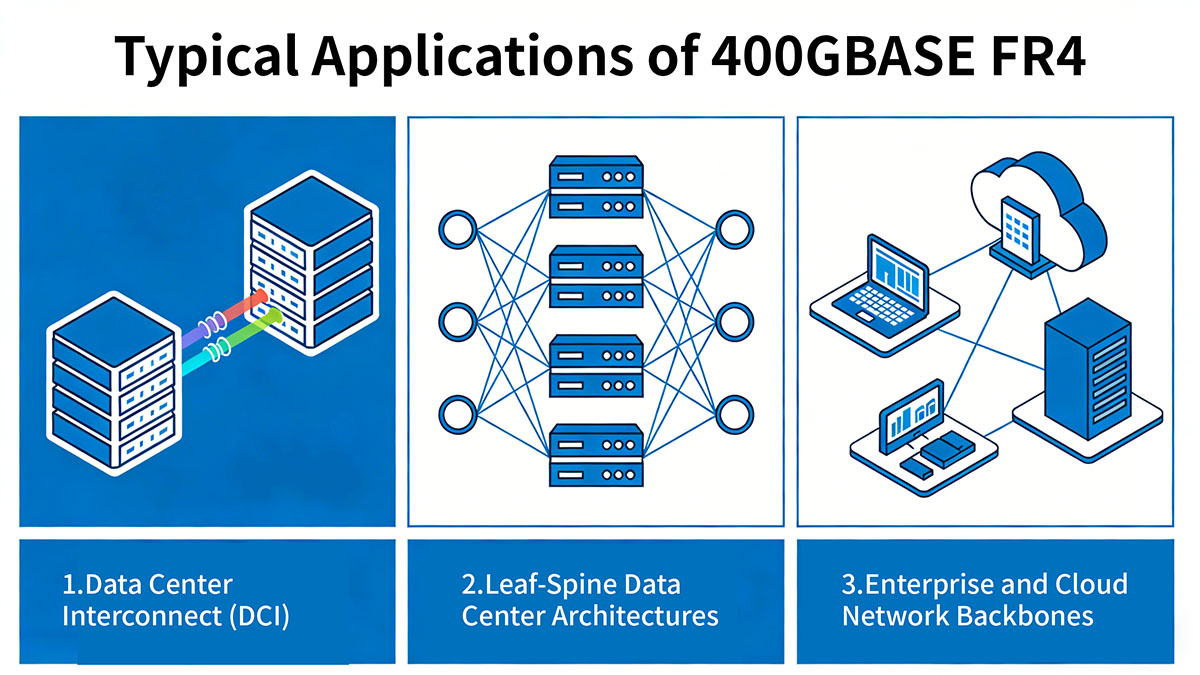
400GBASE FR4 is primarily used in medium-reach high-bandwidth optical links that require efficient fiber usage. With support for up to 2km transmission over duplex single-mode fiber, it fits well between short-reach parallel optics and longer-distance metro optics.
Because it requires only two fibers while delivering 400Gbps bandwidth, FR4 is widely deployed in modern data center architectures, large campus networks, and cloud infrastructure environments.
Data Center Interconnect (DCI)
One of the most common applications of 400GBASE FR4 is data center interconnect within the same campus or between nearby buildings. Many large data centers consist of multiple facilities distributed across a campus, requiring high-capacity links between them.
| Connection Type | Typical Distance | Suitable Standard |
|---|---|---|
| Intra-rack | <10m | DAC / AOC |
| Inter-rack | 50–100m | 400GBASE SR8 |
| Data center building-to-building | 500m–2km | 400GBASE FR4 |
In these scenarios, FR4 provides sufficient reach to connect separate data halls or buildings while avoiding the need for parallel fiber trunks. Its duplex fiber design allows operators to reuse existing single-mode infrastructure while upgrading network capacity to 400Gbps.
Leaf–Spine Data Center Architectures
Modern data centers often adopt spine-leaf architecture to support high east-west traffic between servers and storage systems. In these environments, high-speed links are required between aggregation switches.
Typical FR4 deployment points include:
- Spine-to-spine interconnections
- Core aggregation layers
- Longer leaf-to-spine links in large facilities
These links often extend beyond the reach of short-range standards such as SR8 or DR4, making FR4 a suitable solution when transmission distances approach or exceed several hundred meters.
Because FR4 uses duplex LC fiber instead of MPO fiber arrays, it can also simplify cable management in high-density switching environments.
Enterprise and Cloud Network Backbones
Beyond hyperscale data centers, 400GBASE FR4 is also used in enterprise and cloud backbone networks where high-capacity links are required across large facilities.
| Deployment Environment | Typical Use Case | Distance Range |
|---|---|---|
| Enterprise Campus | Core network backbone | 500m–2km |
| Cloud Data Centers | Inter-building aggregation | 1–2km |
| Research or HPC Networks | High-capacity core links | Up to 2km |
In these environments, FR4 enables organizations to scale network bandwidth without deploying large numbers of parallel fiber cables. This is particularly useful in campuses where fiber infrastructure may already be installed between buildings.
As a result, 400GBASE FR4 has become a practical option for upgrading high-capacity backbone links while maintaining compatibility with standard single-mode fiber infrastructure.
? Deployment Considerations for 400GBASE FR4
Deploying 400GBASE FR4 links requires careful planning of fiber infrastructure, equipment compatibility, and thermal conditions. Although FR4 simplifies cabling by using duplex single-mode fiber, high-speed 400GbE transmission still demands proper network design to ensure stable performance and signal integrity.
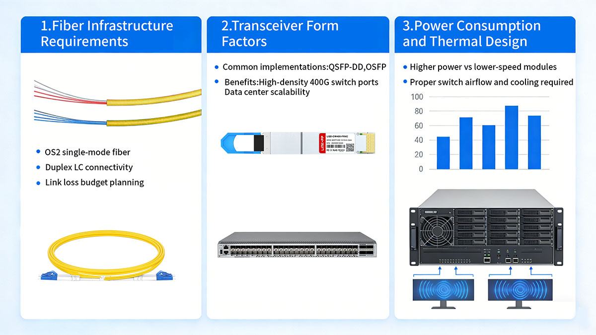
Understanding these deployment considerations helps network engineers build reliable 400G optical links and avoid common integration issues.
Fiber Infrastructure Requirements
400GBASE FR4 operates over duplex single-mode fiber, typically using OS2 fiber that supports long-distance transmission and low attenuation. Proper fiber selection and link budgeting are essential for achieving the full 2km reach.
| Parameter | Typical Requirement |
|---|---|
| Fiber Type | Single-mode fiber (OS2) |
| Connector Type | Duplex LC |
| Maximum Reach | 2km |
When deploying FR4 links, engineers should evaluate several fiber-related factors:
- Link loss budget: Ensure the total optical loss (fiber attenuation, connectors, and splices) remains within the supported range.
- Connector quality: Poor or contaminated connectors can significantly increase insertion loss.
- Fiber routing: Excessive bends or tight cable management may introduce additional signal attenuation.
Maintaining clean connectors and proper fiber handling practices is especially important in high-speed optical networks.
Transceiver Form Factors
400GBASE FR4 optics are typically available in high-density pluggable transceivers form factors designed for modern data center switches and routers.
| Form Factor | Typical Platform |
|---|---|
| QSFP-DD | High-density 400G switches |
| OSFP | Hyperscale data center platforms |
These form factors allow switches to support multiple 400G ports within a compact footprint, enabling large-scale network deployments.
When selecting FR4 modules, compatibility considerations may include:
- Switch vendor firmware requirements
- Transceiver coding or interoperability support
- Port configuration for 400GbE operation
Ensuring that the optical module and switch platform support the same interface specification is necessary for stable link establishment.
Power Consumption and Thermal Design
400G optical modules consume significantly more power than lower-speed optics due to high-speed signal processing and multiple optical channels. Proper thermal management is therefore essential for stable operation.
| Optical Module Type | Typical Power Consumption |
|---|---|
| 100G Optical Module | ~3–4W |
| 400G FR4 Module | ~10–12W |
Because of this higher power usage, network equipment must provide:
- Adequate airflow across switch ports
- Proper rack-level cooling
- Sufficient power delivery to transceiver slots
In high-density switch environments, large numbers of 400G QSFP-DD transceiver operating simultaneously can increase overall thermal load. Designing racks with appropriate airflow direction and cooling capacity helps maintain stable optical performance.
By considering fiber infrastructure, hardware compatibility, and thermal requirements during deployment, organizations can ensure that 400GBASE FR4 links operate reliably in high-capacity Ethernet networks.
? Future Outlook for 400GBASE FR4
As network traffic continues to grow across cloud platforms, artificial intelligence workloads, and large-scale data processing systems, Ethernet speeds are steadily moving toward higher capacities. Within this evolution, 400GBASE FR4 is expected to remain an important optical interface for medium-reach links, particularly in environments that require efficient fiber utilization and scalable bandwidth.
Its combination of duplex single-mode fiber connectivity, CWDM multiplexing, and 2km transmission reach makes FR4 well suited for the current generation of high-density data center networks.
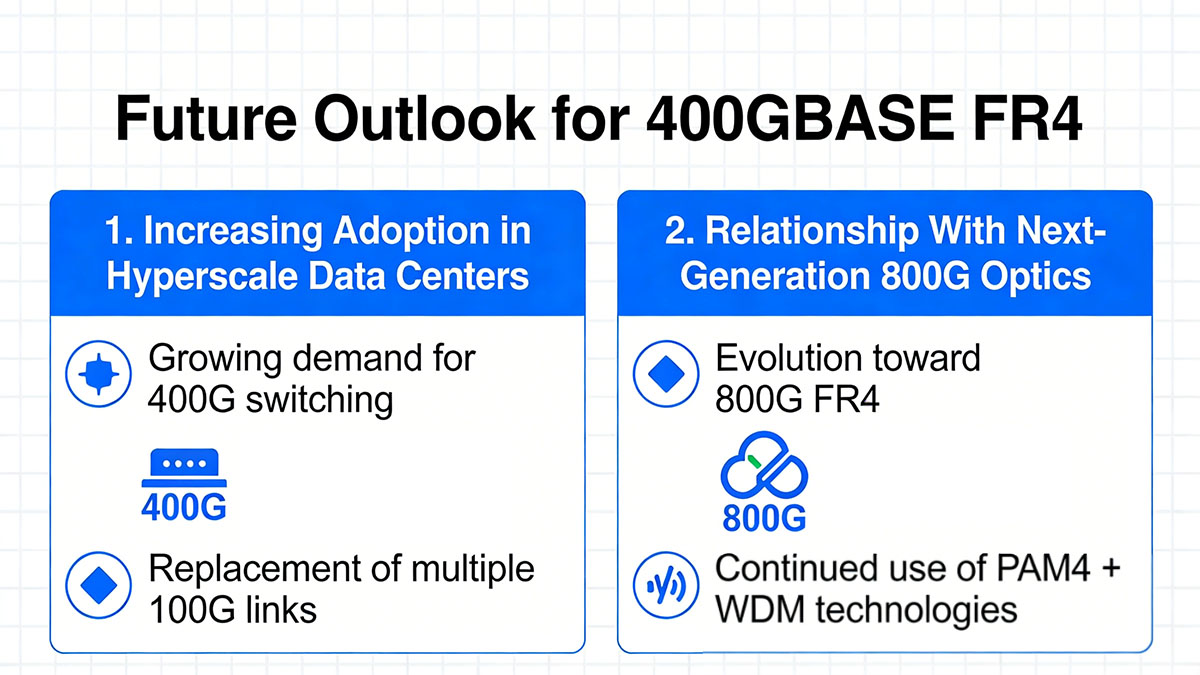
Increasing Adoption in Hyperscale Data Centers
Many hyperscale and cloud data centers are transitioning from 100GbE and 200GbE architectures to 400GbE switching fabrics. In these environments, FR4 provides a practical solution for medium-distance optical links between switching layers and across large facilities.
| Network Upgrade Stage | Typical Link Speed | Common Optical Standard |
|---|---|---|
| Early cloud deployments | 40G / 100G | LR4, SR4 |
| Large-scale data centers | 100G / 200G | CWDM4, DR4 |
| Modern hyperscale fabrics | 400G | FR4, DR4 |
Because FR4 supports longer reach than DR4 while using only a duplex fiber pair, it is often used for inter-building connectivity and extended aggregation links within large data center campuses.
As cloud infrastructure continues to scale, the ability to deliver high bandwidth with efficient fiber usage will remain a key advantage.
Relationship With Next-Generation 800G Optics
The development of 800GbE networking technologies is already underway, and many of the design principles used in FR4 are being extended to these higher-speed optical interfaces.
| Ethernet Generation | Optical Lanes | Typical Architecture |
|---|---|---|
| 400G Ethernet | 4 × 100Gbps | PAM4 + CWDM |
| 800G Ethernet | 4 × 200Gbps or 8 × 100Gbps | Advanced PAM4 + WDM |
Future optical modules such as 800G FR4 continue to use similar concepts:
- Multiple wavelength channels
- PAM4 modulation
- Wavelength multiplexing over duplex single-mode fiber
This technological continuity allows network designers to transition toward higher speeds while maintaining familiar optical architectures.
As a result, 400GBASE FR4 not only supports current high-capacity networks but also serves as an important stepping stone toward next-generation Ethernet technologies.
? FAQs About 400GBASE FR4
What does FR4 mean in 400GBASE FR4?
FR4 refers to a fiber-based Ethernet interface that uses four optical wavelengths to transmit data. In the 400GBASE FR4 standard, each wavelength carries 100Gbps, delivering a combined total of 400Gbps over duplex single-mode fiber.
What wavelengths are used in 400GBASE FR4?
400GBASE FR4 uses four CWDM wavelengths centered around 1271nm, 1291nm, 1311nm, and 1331nm. These wavelengths are multiplexed into a single fiber pair using coarse wavelength division multiplexing technology.
How many fibers does 400GBASE FR4 require?
400GBASE FR4 operates over two fibers (a duplex fiber pair). This design allows four optical channels to share the same fiber pair through wavelength multiplexing, reducing cabling complexity compared with parallel optical standards.
What connector type is used for 400GBASE FR4?
Most 400GBASE FR4 optical modules use a duplex LC connector. This connector type is widely supported in single-mode fiber networks and simplifies integration with existing fiber infrastructure.
Is 400GBASE FR4 compatible with QSFP-DD switches?
Yes. Many QSFP-DD and OSFP transceivers implement the 400GBASE FR4 optical interface, allowing them to operate in 400GbE switch ports that support these form factors.
What is the typical use case for 400GBASE FR4?
400GBASE FR4 is commonly used for data center interconnect, spine-layer aggregation links, and campus backbone connections where transmission distances can reach up to 2km over single-mode fiber.
? Conclusion
400GBASE FR4 has become an important optical interface standard for modern high-speed Ethernet networks. By combining PAM4 modulation with CWDM wavelength multiplexing, it enables 400Gbps transmission over duplex single-mode fiber with a reach of up to 2km. This architecture allows network operators to achieve high bandwidth while maintaining efficient fiber utilization and simplified cabling infrastructure.
Compared with other 400G optical standards, FR4 provides a practical balance between transmission distance, fiber efficiency, and deployment flexibility. Its ability to operate over a standard LC duplex fiber pair makes it particularly suitable for data center interconnects, large campus networks, and cloud infrastructure environments where medium-range high-capacity links are required.
As data centers continue to scale and transition toward higher-speed architectures, technologies such as 400GBASE FR4 play a key role in supporting the growth of modern Ethernet networks while maintaining compatibility with existing fiber infrastructure.
For organizations planning to deploy 400G connectivity, exploring reliable and interoperable optical modules is an important step in building stable network links. You can learn more about compatible high-performance optical transceivers by visiting the LINK-PP Official Store, where a range of solutions designed for modern data center networking is available.







