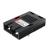
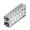
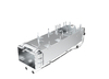
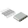

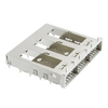

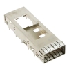
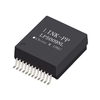
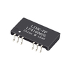
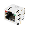
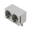


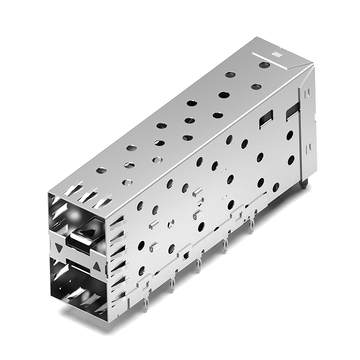



Selecting the right SFP+ cage configuration helps ToR switch designers fit the required optical ports into a compact enclosure while accounting for EMI shielding and mechanical integration. The design must match the port layout, PCB footprint, and front-panel structure because no single cage arrangement suits every switch.
A Top-of-Rack (ToR) switch connects servers, storage devices, and other network equipment within a data center rack. These switches often require multiple optical interfaces in a limited front-panel area, making port arrangement an important part of hardware design.
Beyond holding optical transceivers in place, the cage provides mechanical support and forms part of the equipment's EMI shielding structure. Its configuration and installation must work with the PCB, front panel, and surrounding chassis.
Why SFP+ Cage Design Matters in ToR Switches
ToR switches need carefully planned optical port layouts to accommodate multiple connections within a compact enclosure. The selected cage structure affects how efficiently these interfaces use available space, how they integrate with the PCB, and how electromagnetic interference is controlled.
Supporting High Port Density in Compact ToR Switches
High port density allows a ToR switch to provide more optical connections within a limited front-panel area. This is important in data centers where rack space is limited and network equipment needs to accommodate multiple server connections.
Each SFP+ port requires a cage to hold and align the optical transceiver. When a switch needs many ports, their arrangement directly affects how efficiently the available front-panel space is used.
For example, a switch with multiple optical uplink ports may need several cage assemblies arranged in one or more rows. A suitable layout helps increase the number of available connections without requiring a larger equipment enclosure.
However, adding more ports is not simply a matter of placing additional cages side by side. Designers must also consider the spacing between adjacent interfaces, module insertion space, and the mechanical structure of the front panel.
Addressing Space Constraints in ToR Switch Enclosures
A compact ToR switch has limited space for optical interfaces, PCB components, power circuits, and other hardware. The port arrangement must fit within this available space while leaving sufficient room for assembly and maintenance.
The overall layout also needs to account for the position of nearby electronic components. Crowded component placement can make assembly more difficult and restrict access to individual optical ports.
Designers should consider three main space requirements:
- Port Spacing: Allow suitable distances between adjacent interfaces to accommodate cage structures and installed transceivers.
- Component Clearance: Keep enough space around nearby PCB components and other mechanical structures.
- Module Access: Provide sufficient room for inserting, locking, and removing optical transceivers.
These requirements help ensure that a compact port arrangement remains practical during equipment assembly and routine maintenance.
Meeting EMI Requirements in Dense Port Arrays
Electromagnetic interference (EMI) is unwanted electromagnetic energy that can affect the operation of nearby electronic circuits. In a ToR switch, multiple high-speed interfaces, power components, and other electronic circuits operate within a relatively small enclosure.
As port density increases, designers need to pay closer attention to how electromagnetic emissions are contained around the optical interfaces. The metal cage provides a conductive enclosure around the transceiver and can form part of the equipment's overall EMI shielding structure.
However, the cage alone cannot guarantee that the complete switch meets its electromagnetic compatibility (EMC) requirements. Its shielding performance also depends on electrical contact with the front panel, grounding connections, and the surrounding chassis structure.
For this reason, EMI requirements should be considered during the early stages of switch design rather than addressed only after the hardware has been assembled.
Choosing the Right SFP+ Cage Configuration for ToR Switches
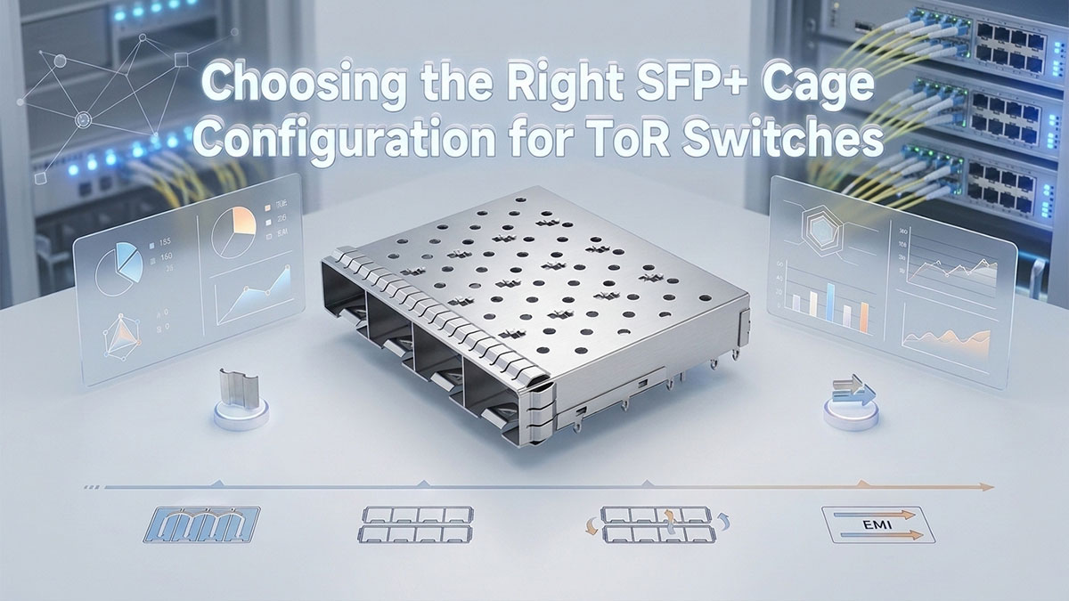
The right configuration depends on the number of optical ports, available front-panel space, and PCB layout of the ToR switch. Single-port, ganged, and stacked designs offer different ways to arrange SFP+ interfaces, allowing equipment designers to select a structure that fits their hardware requirements.
| Cage Configuration | Port Arrangement | Main Design Advantage | Suitable Application |
| Single-Port | One independent port | Flexible port placement | Individual or distributed interfaces |
| Ganged | Multiple ports in one horizontal row | Consistent multi-port alignment | Switches with adjacent optical ports |
| Stacked | Multiple rows of ports | Higher port density within a compact layout | High-density ToR switches |
The following sections explain how each configuration works and what to consider when selecting one for a network switch.
Single-Port Cage for Individual Port Layouts
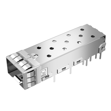
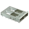
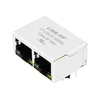
A Single-Port Cage holds one SFP+ transceiver and provides an individual mounting position on the equipment's front panel. Each unit can be placed separately, giving designers more flexibility when arranging optical interfaces around other components.
This configuration is useful when a switch requires only a few SFP+ ports or when the interfaces need to be positioned at different locations. It also allows designers to plan individual port positions without using a multi-port cage assembly.
For example, the LINK-PP LP11BCS2000 SFP+ 1×1 Cage features an EMI spring finger and a grounding pin. Its through-hole, right-angle mounting design supports PCB installation, while the shielding features provide a conductive contact structure for EMI control.
This model is worth considering when an individual port layout requires both mechanical support and EMI-related features. Its separate configuration also gives designers more freedom when integrating optical interfaces into a customized front-panel design.
Ganged Cage for Multiple Horizontal Ports
A Ganged Cage combines multiple SFP+ openings into one assembly, allowing several transceivers to be arranged in a single horizontal row. Instead of positioning each port separately, designers can use one multi-port structure to maintain consistent spacing and alignment.
This arrangement is suitable for ToR switches that require several adjacent optical interfaces. Grouping multiple openings into one assembly can simplify the mechanical layout and provide a consistent port arrangement.
The number of ports depends on the selected configuration. For example, a 1×4 design provides four adjacent openings in one row, making it suitable for equipment that needs a compact group of optical connections.
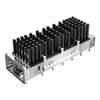
The LINK-PP LP14BC02000D SFP+ 1×4 Cage is one option for this type of layout. It features an EMI spring finger and a press-fit termination, with four ports integrated into a single cage assembly. Its design is intended for PCB layouts with a matching four-port footprint.
When selecting this type, designers should check the spacing between ports, PCB footprint, and front-panel opening dimensions. These details help ensure that the complete assembly fits the intended switch enclosure.
Stacked Cage for Higher Port Density
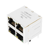
A Stacked Cage arranges SFP+ ports in two or more vertical rows, allowing equipment designers to increase the number of interfaces within a limited front-panel width. This configuration is particularly useful when a switch needs many optical connections but has limited horizontal space.
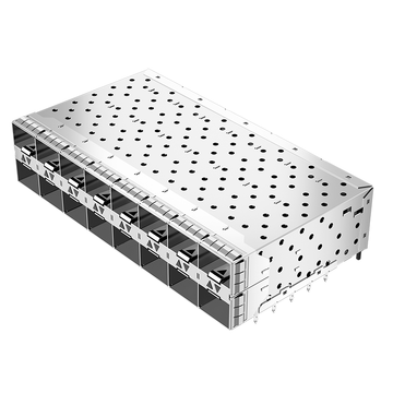
For example, a 2×8 arrangement provides 16 ports across two rows, with eight openings in each row. Compared with placing all 16 interfaces in one horizontal line, this layout uses the available panel height to accommodate more connections.
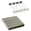
The LINK-PP LP28BC01203 SFP+ 2×8 Cage Assembly is designed for this type of high-density arrangement. It combines 16 SFP+ ports with press-fit termination, EMI spring features, and an integrated inner light pipe. The light pipe helps carry port-status indications from the PCB toward the equipment's front panel.
This configuration can be useful for ToR switches that need a large number of optical interfaces in a compact enclosure. However, designers should also check the vertical clearance between rows, module insertion space, and accessibility of the upper and lower ports.
A stacked arrangement requires careful mechanical and PCB planning to ensure that all interfaces remain accessible during installation and maintenance.
How SFP+ Cage Design Affects EMI Shielding
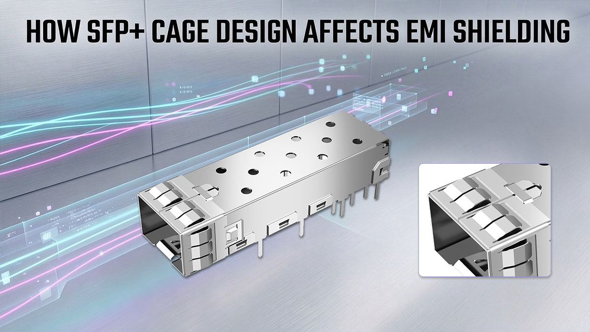
EMI shielding is an important part of cage design, especially when multiple optical ports are installed close together in a compact switch enclosure. A suitable shielding structure helps contain electromagnetic emissions around the interfaces and reduces the risk of interference with nearby electronic components.
The shielding design mainly depends on the conductive structure of the cage and the way it interacts with the surrounding metal enclosure. Metal spring fingers and conductive elastomeric gaskets are two common solutions used to provide electrical contact and help control electromagnetic emissions.
Metal Spring Fingers for EMI Containment
Metal spring fingers are flexible conductive contacts formed on or fitted to the cage assembly. They provide contact points along the shielding interface and help limit gaps between the cage and surrounding metal structures.
These small metal features can flex when the assembly is installed, allowing them to accommodate minor variations in the mating surfaces. Their spring structure also helps maintain contact without requiring a completely rigid interface.
For high-density ToR switches, this approach provides a compact shielding solution that can be incorporated into individual or multi-port cage assemblies.
When evaluating this feature, designers should review the spring finger position, contact geometry, and compatibility with the surrounding enclosure. These details influence how the shielding structure fits into the complete equipment design.
Elastomeric Gaskets for Conductive Contact
Conductive elastomeric gaskets provide another way to establish electrical contact between a cage assembly and surrounding metal structures. Unlike individual metal contacts, these gaskets use flexible conductive material across a defined interface.
Their flexible structure allows them to accommodate small gaps and surface variations between mating components. This makes them useful in designs where a more continuous conductive contact area is required.
The effectiveness of a gasket depends on its conductive properties, contact area, and the mechanical design of the surrounding components. Designers should also consider available installation space and the specified compression range.
The selected gasket must fit the equipment structure and maintain suitable contact under the intended operating conditions.
Selecting the Right EMI Shielding Structure
Metal spring fingers and conductive elastomeric gaskets both provide electrical contact, but their structures and installation requirements are different. The appropriate option depends on the cage design, front-panel construction, and shielding requirements of the complete switch enclosure.
The following factors can help narrow down the selection:
- Contact Structure: Determine whether the design requires localized metal contact points or a more continuous conductive interface.
- Available Space: Check the area around the cage and front panel to ensure that the selected shielding feature fits the enclosure.
- Mechanical Tolerances: Review dimensional variations between mating components and confirm that the shielding structure can accommodate them.
- Assembly Requirements: Consider how the shielding feature is installed and whether it fits the planned equipment assembly process.
For multi-port ToR switches, the shielding structure should be selected as part of the overall cage and enclosure design. A suitable combination helps maintain conductive contact while meeting the space and mechanical requirements of high-density port layouts.
Ensuring Proper SFP+ Cage Grounding in ToR Switches
Proper grounding is essential for maintaining effective EMI shielding in ToR switches. The cage must establish reliable electrical contact with the surrounding conductive structure, including the front-panel bezel and chassis, as specified by the equipment's grounding design.
This connection depends on the cage's grounding features and the mechanical fit of the assembled components. Even when a cage includes grounding fingers, incorrect positioning or insufficient contact can affect the intended shielding performance.
Establishing Contact Between Cage and Bezel
The front-panel bezel provides an important contact surface for the cage's grounding features. When the cage is installed, its conductive grounding fingers or other designated contact points should meet the corresponding metal surface of the bezel.
This contact helps establish an electrical connection between the cage and equipment enclosure. It allows the cage to become part of the chassis-level EMI shielding structure rather than functioning as an isolated metal component.
For switches with multiple optical ports, consistent contact is important across the complete cage arrangement. If some contact points do not meet the bezel correctly, gaps in the intended conductive interface may affect EMI containment.
Designers should therefore check the cage position, bezel opening, and contact locations together. The selected components must fit properly to maintain the intended grounding path throughout the assembled equipment.
Maintaining Proper Grounding Finger Compression
Grounding fingers are designed to flex when the cage meets the front-panel bezel. This flexibility allows them to maintain conductive contact while accommodating small differences in component dimensions.
Proper compression is important because the fingers must remain in contact with the bezel after the equipment is fully assembled. If compression is insufficient, the contact may become unstable. Excessive compression, on the other hand, can deform the fingers or place unnecessary mechanical stress on the cage and bezel.
The required compression range depends on the specific cage design and its mechanical specifications. Designers should follow the manufacturer's recommended dimensions rather than applying the same compression requirement to every cage assembly.
During enclosure design, the following factors should be considered:
- Contact Position: Align the grounding fingers with the intended conductive surface of the bezel.
- Compression Range: Maintain the specified working range to avoid insufficient contact or permanent deformation.
- Mechanical Clearance: Ensure that the bezel does not interfere with the cage structure or module locking mechanism.
These considerations help maintain consistent contact without affecting the mechanical operation of the optical interfaces.
Checking Grounding Connections During Assembly
Grounding connections should be checked during equipment assembly to identify potential contact problems before the switch enters final testing. Both the mechanical fit and electrical continuity need to be considered.
First, inspect whether the cage is correctly seated on the PCB and whether its grounding features are positioned as intended. Bent fingers, incorrect alignment, or incomplete installation can affect the final contact condition.
Next, check the fit between the cage and front-panel bezel. The grounding features should contact the designated conductive surfaces without excessive deformation or mechanical interference.
Electrical continuity can also be measured between the designated cage grounding point and the chassis grounding reference. The measured result should be evaluated against the equipment's grounding design and applicable test requirements.
A practical assembly inspection should include the following checks:
- Cage Position: Confirm that the cage is correctly installed and aligned with the PCB.
- Grounding Contact: Inspect the contact between grounding features and the front-panel bezel.
- Electrical Continuity: Verify the intended conductive path using the specified test method.
- Mechanical Condition: Check for bent fingers, loose connections, or interference with module insertion and removal.
Checking these details during assembly helps identify grounding issues early. However, electrical continuity alone does not establish that the complete switch meets its EMI or EMC requirements.
Matching SFP+ Cage Layouts with PCB and Bezel Designs

Proper mechanical integration is essential when installing cage assemblies in ToR switches. The mounting layout must match the PCB footprint and front-panel bezel openings to ensure accurate positioning, secure installation, and smooth module insertion and removal.
These requirements become more important when multiple optical ports are arranged in a compact enclosure. Differences in mounting positions, opening dimensions, or component clearances can affect the assembly process and operation of the installed transceivers.
Selecting Compatible PCB Cage Footprints
A PCB footprint defines the positions and dimensions of the holes and mounting points used to install a cage assembly. Each design has specific mounting requirements, so the selected footprint must match the corresponding mechanical drawing and PCB layout.
For through-hole and press-fit designs, the hole positions, dimensions, and tolerances must meet the cage manufacturer's specifications. Incorrect hole dimensions or mounting positions can make installation difficult and may affect the mechanical stability of the assembly.
Designers should also check the position of the electrical connector relative to the cage opening, where applicable. The connector must align with the installed transceiver so that the module can be inserted without unnecessary force or misalignment.
Before finalizing the PCB layout, consider the following points:
- Mounting Hole Pattern: Match the PCB hole positions with the cage's mounting pins.
- Hole Dimensions: Follow the specified hole diameters and tolerances for the selected termination type.
- Connector Position: Ensure that the electrical connector aligns with the cage and transceiver interface.
- Board Thickness: Confirm that the PCB thickness is suitable for the cage mounting design.
Using the correct footprint helps reduce assembly problems and supports consistent positioning across multiple optical ports.
Coordinating Cage Positions and Bezel Openings
The front-panel bezel contains openings that allow optical transceivers to be inserted into the installed cages. These openings must align with the cage positions to provide a clear path for module installation and removal.
For multi-port assemblies, the spacing between adjacent openings must correspond to the port pitch of the selected cage. Even small positioning differences can cause alignment problems when the assembly is mounted behind the front panel.
Designers should also consider the dimensions of each opening. The bezel cutouts must provide sufficient clearance for the transceiver housing and its insertion path without interfering with the surrounding panel structure.
A coordinated design should address three main dimensions:
- Horizontal Alignment: Match the center positions of the bezel openings with the corresponding cage ports.
- Vertical Alignment: Maintain the correct height between the PCB-mounted assembly and front-panel openings.
- Opening Clearance: Follow the specified cutout dimensions to avoid obstructing module insertion and removal.
Checking these dimensions together helps ensure that the PCB-mounted assembly fits correctly behind the equipment's front panel.
Avoiding Mechanical Interference in Multi-Port Layouts
Multi-port assemblies require careful mechanical planning because several transceivers and their mounting structures occupy the same area. If surrounding components are too close, they may interfere with module installation, latch operation, or routine maintenance.
For example, adjacent cage assemblies must have enough clearance to prevent their housings or mounting features from overlapping. Designers should also consider nearby capacitors, connectors, heatsinks, and other PCB components when arranging multiple optical interfaces.
The front-panel structure needs similar attention. Screws, panel edges, and other mechanical features should not obstruct the module latch or the space required to remove a transceiver.
For stacked configurations, the vertical spacing between the upper and lower rows also needs to accommodate the module housing and its removal mechanism. This is particularly important when technicians need to access individual ports without disturbing neighboring connections.
To reduce mechanical interference, designers should:
- Check Component Clearance: Keep sufficient space between cage assemblies and nearby PCB components.
- Review Latch Movement: Ensure that adjacent structures do not obstruct module locking and release operations.
- Verify Removal Space: Allow enough room to insert and remove transceivers from each port.
- Inspect Stacked Layouts: Confirm that both rows remain accessible after the complete enclosure is assembled.
A well-coordinated mechanical layout helps maintain module access and simplifies the assembly and maintenance of high-density ToR switches.
How to Select and Validate an SFP+ Cage for ToR Switches
Selecting a suitable cage requires more than confirming its port count or shielding features. Equipment designers should review the complete mechanical and electrical requirements before approving a model for prototype integration.
The following table provides a practical overview of the main selection stages and the information that should be confirmed.
| Selection Stage | Key Questions |
Required Output |
| Port Layout | How many ports are needed, and how should they be arranged? | Confirmed cage configuration |
| EMI Design | Which shielding and grounding features does the enclosure require? | Defined shielding interface |
| Mechanical Integration | Does the cage match the PCB and chassis design? | Verified mechanical compatibility |
| System Validation | Does the assembled equipment meet its design requirements? | Completed inspection and test results |
These stages help turn the earlier design considerations into a clear selection process.
Confirming Port Count and Cage Arrangement
Start by determining the total number of optical interfaces required by the switch. Then identify whether they should be arranged individually, in one horizontal row, or across multiple rows.
The selected configuration should fit the available front-panel area without restricting access to adjacent ports or other equipment interfaces.
It is also useful to consider possible changes in the equipment design. If additional optical connections may be required in a later version, the initial layout should account for the available expansion space.
Reviewing EMI Shielding and Grounding Requirements
Next, identify the shielding structure required by the switch enclosure. Review whether the selected assembly uses metal spring fingers, conductive gaskets, or another specified contact arrangement.
Check that these features are compatible with the planned front panel and chassis structure. The grounding arrangement should also match the equipment's electrical design.
The final shielding performance must be evaluated using the complete equipment assembly. A cage's individual shielding features should not be treated as proof of system-level EMI or EMC compliance.
Checking PCB and Chassis Compatibility
Before approving a model, compare its mechanical drawing with the actual PCB layout and front-panel design. Confirm the mounting pattern, termination type, board thickness requirements, port positions, and bezel opening dimensions.
A prototype assembly can then be used to check module insertion, latch operation, removal clearance, and mechanical alignment.
Finally, perform the required electrical and system-level EMI/EMC tests according to the equipment specifications. This helps identify integration issues before the design moves into production.
Building Reliable ToR Switch Designs with the Right SFP+ Cage

Selecting a suitable cage configuration helps equipment designers balance port density, EMI shielding, and mechanical integration in ToR switches. The right choice depends on the required optical interfaces, PCB layout, and front-panel structure, rather than port count alone.
LINK-PP offers different SFP+ cage configurations, including single-port, ganged, and stacked designs, to accommodate various network equipment layouts. Options with different mounting methods and EMI shielding features allow equipment manufacturers to identify assemblies that match their project requirements.
Explore the LINK-PP SFP+ cage product range to find a suitable solution for your switch design. Visit the LINK-PP Official Store to review available models or contact our sales team for product selection and project inquiries.