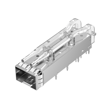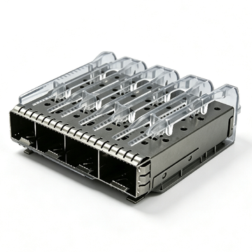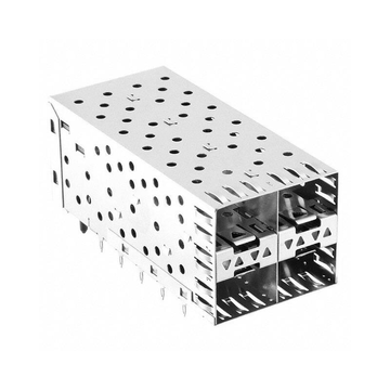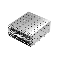
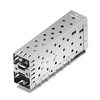
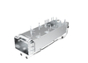
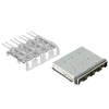

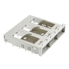

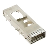
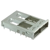
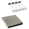
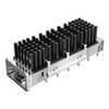
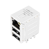
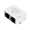
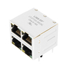


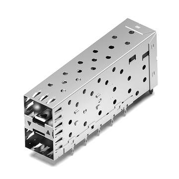



SFP cage assemblies play an important role in high-speed networking equipment, providing mechanical protection, EMI shielding, and a reliable interface for pluggable optical transceivers. Beyond these functions, LED indicators on the PCB help engineers and network operators monitor port status, link activity, and potential connection issues. Light pipes make these indicators visible from the equipment's front panel by directing light from internal LEDs to external viewing positions.
However, an improperly selected SFP cage light pipe can cause light leakage, cross-illumination between adjacent ports, uneven brightness, and front-panel misalignment. These problems are particularly challenging in high-density switch designs, where limited PCB space and closely spaced SFP ports leave little room for mechanical adjustment. Selecting a suitable light pipe therefore requires careful consideration of optical performance, dimensions, material properties, and mounting structures.
In this guide, we examine the key factors involved in SFP cage light pipe selection, including:
-
How SFP cage light pipes work and the configurations available.
-
Common causes of light leakage, poor visibility, and panel misalignment.
-
Optical and mechanical design considerations for reliable integration.
-
Practical inspection methods and compatibility checks, including LINK-PP SFP Cage solutions.
Understanding these factors helps hardware engineers establish a more reliable LED indication system while improving front-panel appearance, assembly consistency, and long-term equipment performance.
What Is an SFP Cage Light Pipe and How Does It Work?
An SFP cage light pipe is an optical component integrated into or attached to an SFP cage assembly. It transfers light from PCB-mounted LEDs to the equipment's front panel, allowing users to observe port status without opening the chassis. It does not generate light itself; instead, it captures, guides, and delivers light from the LED to a visible position.
In networking switches, routers, storage equipment, and telecommunications hardware, this arrangement makes port-level diagnostics easier while maintaining a compact front-panel layout.
Basic Structure and Components of an SFP Cage Light Pipe
An SFP cage light pipe generally consists of an optical transmission body, an LED-facing input, a front-facing output, and mechanical positioning features. Its geometry determines how efficiently light travels from the PCB to the front panel.
The main components include:
-
Optical transmission body: A transparent or translucent structure that guides LED illumination along a defined path.
-
Input end: Positioned near the PCB-mounted LED to capture emitted light.
-
Output end: Directs light toward the front-panel opening or viewing area.
-
Mounting features: Clips, brackets, locating structures, or integrated cage features that maintain the light pipe's position.
-
Light-blocking structures: Where required, opaque barriers help prevent light from spreading into adjacent indicator channels.
The light pipe may be manufactured as an independent component or integrated into the SFP cage assembly. Integrated designs can reduce the number of separate parts and simplify positioning during PCB and chassis assembly.
How Light Pipes Transmit LED Signals in SFP Cage Assemblies
SFP cage light pipes work by capturing light emitted from an LED and guiding it toward the front panel through controlled optical transmission. Their performance depends on the alignment of the input, the optical properties of the material, and the geometry of the transmission path.
The transmission process generally follows these steps:
-
A PCB-mounted LED generates light according to the network port's operating status.
-
The input end of the light pipe captures a portion of the LED's emitted light.
-
The optical body guides the light along its internal transmission path.
-
The output end directs the light toward the front-panel viewing position.
-
The user observes the illuminated indicator without needing direct access to the PCB.
Total internal reflection can help guide light through transparent optical materials when the geometry and surrounding interfaces are properly designed. Surface quality, material transparency, and alignment all influence the amount of light reaching the output.
A well-designed light pipe therefore needs to do more than transmit light. It must deliver consistent visibility while minimizing optical loss and unwanted illumination.
Common Light Pipe Configurations for SFP Cages
SFP cage light pipe configurations differ in the number of optical channels, mounting arrangements, and transmission directions. The appropriate configuration depends on the LED layout, port density, and front-panel design.
Common configurations include:
-
Single-channel light pipes: Guide light from one LED to one front-panel indicator.
-
Dual-channel light pipes: Support two independent LED indicators, often used for different port-status functions.
-
Inner light pipes: Route LED signals through the inner region of a cage assembly.
-
Outer light pipes: Position light transmission paths along the outer region of the cage.
-
Integrated light pipe assemblies: Combine the optical guide with the cage structure to simplify mechanical installation.
-
Separate light pipe assemblies: Use independent optical components that can be positioned or replaced separately.
For multi-port SFP cages, light pipe arrangements may be designed around horizontal, vertical, or stacked port layouts. The number and location of optical channels should correspond to the actual PCB LED arrangement.
Engineers should confirm whether a cage includes inner, outer, or combined light pipe options before finalizing the mechanical design. These configurations are not automatically interchangeable.
Common Problems Caused by Improper SFP Cage Light Pipe Selection
Incorrect SFP cage light pipe selection can lead to optical indication problems and mechanical integration failures. The most common issues include light leakage, cross-illumination, poor LED visibility, front-panel misalignment, and unstable mounting.
These problems may appear during prototype assembly or become more noticeable after the equipment enters regular operation.
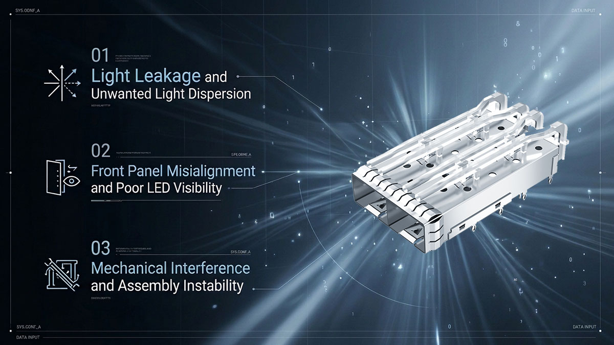
Light Leakage and Unwanted Light Dispersion
Light leakage occurs when LED illumination escapes from the intended optical path or passes through unintended gaps in the assembly. In high-density SFP port layouts, this can make individual indicators difficult to distinguish.
Typical causes include:
-
Gaps between the light pipe output and the front-panel aperture.
-
Excessive clearance between adjacent optical channels.
-
Poor optical isolation in multi-port cage assemblies.
-
Inappropriate material transparency or surface geometry.
-
Incorrect positioning of the LED-facing input.
-
Uncontrolled light reflection from nearby mechanical surfaces.
Cross-illumination is particularly problematic in switches with closely spaced SFP ports. For example, when one port's activity LED illuminates an adjacent indicator, technicians may misinterpret which port is transmitting data.
To reduce this risk, each light pipe channel should have a clearly defined optical path. Where necessary, opaque partitions or light-blocking features can separate neighboring channels.
Front Panel Misalignment and Poor LED Visibility
Front-panel misalignment occurs when the light pipe output does not correspond correctly to the panel aperture. Even if the LED and light pipe function properly, incorrect positioning can reduce visibility or create an inconsistent appearance across ports.
Common symptoms include:
-
The light pipe output is partially hidden behind the panel.
-
The optical tip is recessed too far into the enclosure.
-
The light pipe protrudes excessively from the front panel.
-
The LED input is offset from the light pipe's optical entrance.
-
Adjacent port indicators appear at different heights or positions.
-
LED brightness varies because of inconsistent optical coupling.
These problems are often associated with dimensional differences between the PCB, SFP cage, enclosure, and front-panel aperture.
The most effective approach is to establish a common mechanical reference for all four elements before finalizing the light pipe geometry. Adjusting the light pipe alone cannot compensate for an incorrectly positioned cage or PCB.
Mechanical Interference and Assembly Instability
Mechanical interference occurs when the light pipe conflicts with surrounding components or enclosure structures. An unstable mounting arrangement can also allow the light pipe to move during assembly or equipment operation.
Potential problems include:
-
Interference with PCB-mounted LEDs or nearby electronic components.
-
Contact with the front panel during chassis installation.
-
Insufficient clearance around the light pipe.
-
Loose clips or inadequate retention features.
-
Deformation caused by excessive insertion force.
-
Displacement caused by vibration or repeated mechanical handling.
In high-density SFP cage assemblies, small dimensional differences can affect several adjacent optical channels simultaneously.
For this reason, mechanical clearance and retention should be evaluated during the initial design stage rather than treated as final assembly adjustments.
Key Design Factors to Consider When Choosing SFP Cage Light Pipes
Choosing an appropriate SFP cage light pipe requires evaluating its geometry, optical properties, material characteristics, and operating environment. These factors collectively determine whether the light pipe can deliver reliable illumination while fitting the intended cage and enclosure structure.
A suitable design should provide sufficient light transmission without creating unnecessary mechanical complexity.
Light Pipe Geometry, Length, and Cross-Section
Light pipe geometry determines how light travels from the PCB LED to the front-panel output. Length, cross-sectional dimensions, and bend configuration must match the physical distance and positioning of the components.
Important dimensions include:
-
Overall length: Determines whether the light pipe can bridge the distance between the PCB and front panel.
-
Cross-sectional width and height: Affect optical coupling, available installation space, and mechanical clearance.
-
Input dimensions: Determine how effectively the light pipe captures light from the LED.
-
Output dimensions: Influence the illuminated area and compatibility with the panel aperture.
-
Bend radius and angle: Affect the optical transmission path when the LED and front panel are not aligned.
A shorter, more direct optical path generally reduces opportunities for light loss. However, actual geometry must follow the physical constraints of the equipment.
When evaluating light pipe dimensions, engineers should also consider:
-
PCB-to-panel distance.
-
LED package size and position.
-
Cage height and mounting orientation.
-
Front-panel thickness.
-
Available space around neighboring SFP ports.
The dimensional design should be verified against mechanical drawings and physical prototypes. Nominal dimensions alone may not account for manufacturing tolerances or assembly variation.
Optical Performance and Light Transmission Efficiency
Optical performance determines how much LED light reaches the front-panel output and how consistently the indicator appears under different viewing conditions.
The following properties deserve particular attention:
-
Light transmittance: Indicates how much light passes through the optical material.
-
Optical attenuation: Describes light reduction along the transmission path.
-
Surface finish: Influences light reflection, scattering, and output appearance.
-
Internal reflection: Helps guide light through the light pipe body.
-
Output diffusion: Can improve visibility across different viewing angles.
-
Optical isolation: Limits unwanted illumination between neighboring channels.
A clear optical output can provide concentrated illumination, while a diffused or textured output may distribute light across a wider viewing area. The appropriate choice depends on the front-panel indicator design and visibility requirements.
The following table summarizes the main optical considerations.
|
Optical parameter |
Design consideration |
Potential problem if unsuitable |
|---|---|---|
|
Light transmittance |
Select material with suitable transparency |
Dim LED indication |
|
Optical attenuation |
Minimize unnecessary transmission losses |
Uneven brightness |
|
Surface finish |
Match the required reflection and diffusion characteristics |
Glare or poor visibility |
|
Output geometry |
Align the illuminated area with the panel aperture |
Inconsistent indicator appearance |
|
Optical isolation |
Separate adjacent light channels |
Cross-illumination |
|
Transmission path |
Avoid unnecessary bends and obstructions |
Reduced light output |
There is no single optical specification that suits every SFP cage application. Engineers should evaluate the light pipe together with the actual LED, panel geometry, and required indicator visibility.
Material Selection and Environmental Durability
Polycarbonate (PC) and polymethyl methacrylate (PMMA) are two common materials used for optical light pipe applications. Material selection should consider optical clarity, mechanical strength, thermal behavior, and environmental requirements.
Their general characteristics are summarized below.
|
Material characteristic |
Polycarbonate (PC) |
Acrylic (PMMA) |
|---|---|---|
|
Optical clarity |
Good |
Very good |
|
Impact resistance |
Generally high |
Generally lower |
|
Mechanical toughness |
High |
More brittle |
|
Dimensional stability |
Depends on grade and design |
Depends on grade and design |
|
Typical consideration |
Durability and mechanical integration |
Optical clarity and surface appearance |
|
Application suitability |
Light pipes requiring greater impact resistance |
Applications emphasizing optical transmission and appearance |
The actual performance of either material depends on its grade, formulation, processing quality, and operating environment.
When evaluating material specifications, consider:
-
Operating temperature range.
-
Resistance to thermal aging and discoloration.
-
Impact resistance during handling and assembly.
-
Dimensional stability under expected environmental conditions.
-
Flammability rating and applicable safety requirements.
-
Compatibility with the manufacturing and assembly process.
For example, LINK-PP SFP cage product specifications identify clear polycarbonate as the light pipe material in certain SFP+ cage models. The material should still be evaluated against the temperature and mechanical requirements of the target application.
Material selection should ultimately be based on documented component specifications rather than assumptions based only on the generic material name.
How to Prevent Light Leakage in SFP Cage Light Pipe Assemblies
Preventing light leakage requires controlling the optical path, maintaining appropriate interfaces, and separating neighboring LED channels. A well-designed light pipe should direct illumination toward its intended front-panel indicator without allowing excessive light to escape elsewhere.
Both optical design and mechanical assembly contribute to this result.
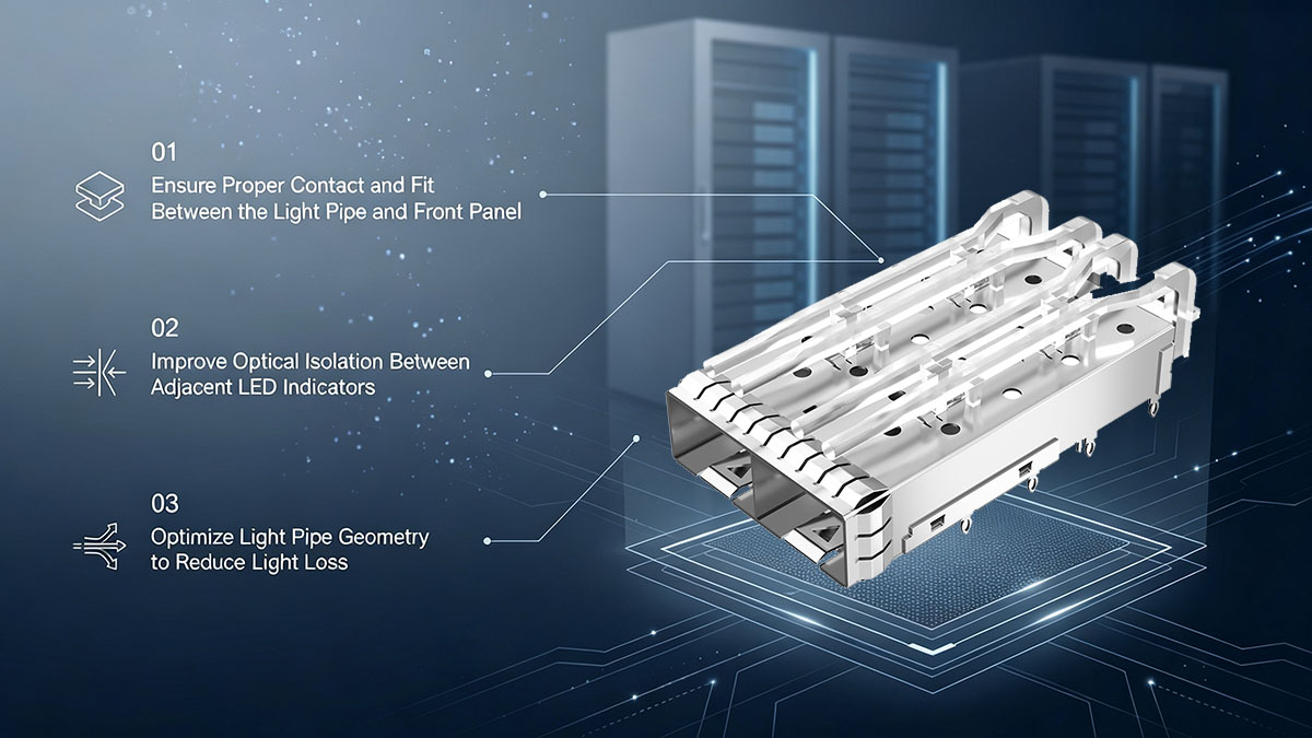
Ensure Proper Contact and Fit Between the Light Pipe and Front Panel
A suitable fit between the light pipe output and front-panel aperture helps prevent unwanted light from escaping around the indicator. The interface should provide sufficient clearance for assembly while avoiding excessive gaps.
Key design measures include:
-
Match the light pipe output dimensions to the front-panel opening.
-
Control the insertion depth and protrusion height.
-
Maintain consistent alignment between the output and aperture centerlines.
-
Avoid excessive clearance around the optical interface.
-
Use suitable locating features to prevent lateral movement.
-
Consider a light-blocking interface where the enclosure design requires additional optical isolation.
It is important to distinguish between mechanical contact and optical coupling. A light pipe should not be forced against the panel or LED if doing so creates stress, deformation, or assembly interference.
The correct interface depends on the enclosure structure, material tolerances, and mounting arrangement. A prototype fit check can reveal problems that are difficult to identify from individual component drawings.
Improve Optical Isolation Between Adjacent LED Indicators
Optical isolation prevents light from one port's LED from appearing in another port's indicator area. This is particularly important in multi-port SFP and SFP+ cage assemblies.
Practical approaches include:
-
Maintain independent optical channels for separate LEDs.
-
Introduce opaque barriers between adjacent light pipes where necessary.
-
Avoid unnecessary shared transparent structures.
-
Control gaps between neighboring optical components.
-
Check the alignment of each input with its corresponding LED.
-
Evaluate reflections from nearby metal and plastic surfaces.
For example, a 1x4 SFP cage has four adjacent ports arranged in a horizontal row. If the optical channels are poorly isolated, illumination from one LED may become visible through neighboring output areas.
An appropriate light pipe design should maintain clear port identification even when multiple LEDs are illuminated simultaneously.
Testing should include different LED colors and operating states, because the visibility of cross-illumination may vary with the light source.
Optimize Light Pipe Geometry to Reduce Light Loss
Optimized light pipe geometry improves the consistency of LED indication and reduces unnecessary light dispersion. The goal is to guide illumination efficiently from the LED input to the front-panel output.
Recommended design practices include:
-
Keep the optical transmission path as direct as the enclosure layout permits.
-
Avoid sharp bends and abrupt cross-sectional changes.
-
Use suitable bend geometry for angled light transmission.
-
Maintain smooth optical surfaces along the transmission path.
-
Align the input end with the LED emission area.
-
Prevent mechanical structures from obstructing the optical channel.
Total internal reflection can be used to guide light through transparent materials, but it depends on the refractive-index relationship and the geometry of the optical interface. Poorly designed bends or surface defects can increase light loss.
Engineers should therefore evaluate the complete light pipe rather than focusing only on its material transparency.
A practical prototype test should compare LED visibility at the input and output under consistent operating conditions. This helps identify excessive attenuation, uneven brightness, and unwanted optical dispersion before production.
How to Prevent Panel Misalignment During SFP Cage Installation
Preventing SFP cage light pipe misalignment requires coordinated dimensional control across the PCB, cage, light pipe, and front panel. The cage mounting position establishes an important mechanical reference, while the light pipe must maintain the correct relationship with the LED and panel aperture.
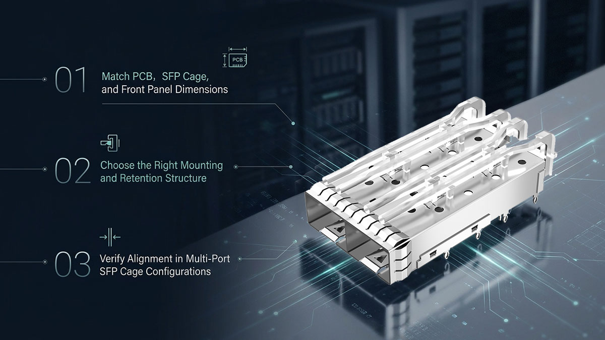
The following measures help reduce alignment errors during equipment assembly.
Match PCB, SFP Cage, and Front Panel Dimensions
The PCB, SFP cage, and front panel should be designed around consistent mechanical reference points. If these components are positioned independently, accumulated tolerances can cause the light pipe output to shift away from the panel opening.
Engineers should verify the following dimensions:
-
PCB-to-front-panel distance.
-
SFP cage mounting position and orientation.
-
Cage height, width, and overall length.
-
LED center position relative to the cage.
-
Front-panel aperture dimensions and centerline.
-
Horizontal and vertical port pitch.
-
Front-panel thickness and installation depth.
A tolerance stack-up analysis is useful when several mechanical components contribute to the final light pipe position.
For example, a small offset in the PCB LED location, combined with a cage mounting deviation and panel aperture tolerance, may result in a visible alignment error at the front of the equipment.
The best practice is to establish a shared datum system in the mechanical drawings and verify the complete assembly against that reference.
Choose the Right Mounting and Retention Structure
The mounting structure determines how securely the light pipe remains in position during assembly and operation. A suitable retention design should prevent unwanted movement without introducing excessive stress.
Common mounting approaches include:
-
Integrated mounting: The light pipe is incorporated into the SFP cage assembly, reducing the number of independent components.
-
Snap-fit retention: Clips or locating features hold the light pipe in a defined position.
-
Bracket-based mounting: A separate support structure positions the optical component.
-
Independent light pipe mounting: The light pipe is installed separately from the cage and aligned with the PCB and panel.
Each arrangement has different assembly and maintenance considerations.
For integrated light pipe designs, engineers should check:
-
Whether the light pipe is securely retained.
-
Whether the mounting features maintain its intended orientation.
-
Whether installation forces could damage the optical body.
-
Whether the structure provides sufficient clearance from nearby components.
-
Whether the light pipe can remain stable during thermal cycling and equipment vibration.
The choice should reflect the actual assembly process. A design that is easy to position during initial installation may still require additional retention if it is exposed to vibration or repeated handling.
Verify Alignment in Multi-Port SFP Cage Configurations
Multi-port SFP cage assemblies require additional alignment control because multiple optical channels share a common mechanical structure. Small deviations may become more noticeable as the number of ports increases.
For horizontal and stacked configurations, verify:
-
Consistent horizontal and vertical spacing between light pipe outputs.
-
Correct alignment with each PCB-mounted LED.
-
Uniform positioning relative to the front-panel apertures.
-
Adequate clearance between neighboring light pipes.
-
Consistent retention across all ports.
-
No interference with transceiver insertion or removal.
The following inspection sequence can help identify alignment problems during prototype assembly:
-
Confirm the PCB and cage mounting references.
-
Install the cage and verify its position.
-
Check the relationship between each LED and light pipe input.
-
Install the front panel or representative enclosure component.
-
Inspect every light pipe output for offset, uneven protrusion, or obstruction.
-
Illuminate each LED individually and then test multiple LEDs simultaneously.
This process helps distinguish mechanical alignment problems from optical transmission issues. It also makes it easier to identify whether an error originates from the PCB layout, cage geometry, light pipe structure, or enclosure design.
SFP Cage Light Pipe Compatibility: What Should Engineers Check?
SFP cage light pipe compatibility depends on the cage form factor, port configuration, LED layout, mounting structure, and front-panel geometry. A light pipe that fits one SFP cage assembly should not automatically be considered compatible with another model.
At LINK-PP, we provide SFP cage configurations with different port arrangements and light pipe options. When evaluating a suitable model, engineers should compare the product drawing and specifications with their actual PCB and enclosure design.
Check SFP Cage Form Factor and Port Configuration
The first compatibility check is to confirm that the SFP cage form factor and port arrangement match the target equipment.
Common configurations include:
-
1x1 SFP cage: A single-port structure for individual optical transceiver interfaces.
-
1x2 SFP cage: Two horizontally arranged ports.
-
1x4 SFP cage: Four horizontally arranged ports for higher front-panel density.
-
1x6 SFP cage: Six ports arranged in a single horizontal row.
-
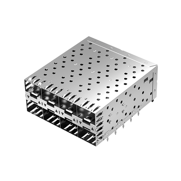
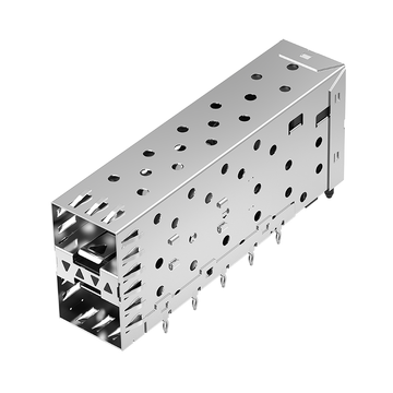
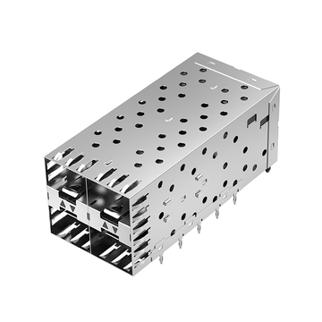
2x2 SFP cage: Four ports arranged in a stacked configuration.
-
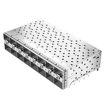
2x4 SFP+ cage: Eight ports arranged in two rows of four.
The selected cage should also match the intended mounting and installation requirements.
Important compatibility checks include:
-
SFP or SFP+ interface type.
-
Port matrix configuration.
-
Overall cage dimensions.
-
PCB termination method, such as press-fit or solder-tail.
-
Right-angle or other mounting orientation.
-
Inner and outer light pipe configuration.
-
EMI spring and grounding arrangements.
Different cage configurations may use different light pipe locations even when they support the same general transceiver form factor.
Therefore, engineers should confirm the exact cage part number and mechanical drawing before approving the component for integration.
Verify Light Pipe and LED Interface Compatibility
Light pipe compatibility must be verified at both ends of the optical transmission path. The input should correspond to the PCB LED position, while the output should match the front-panel aperture.
The main interface checks include:
-
LED package position and orientation.
-
LED-to-light-pipe input distance.
-
Light pipe input dimensions.
-
Optical transmission direction.
-
Front-panel aperture size and center position.
-
Light pipe output height and protrusion.
-
Mechanical clearance around the cage and optical component.
Engineers should also confirm whether the light pipe configuration provides the required number of independent indicator channels.
For example, a cage with inner light pipes may not provide the same front-panel indication arrangement as a model with both inner and outer light pipes. The correct choice depends on the LED layout and the required indicator positions.
A dimensional drawing review should be followed by an assembled prototype test. This is especially important when replacing an existing cage with a different manufacturer's model.
Consider LINK-PP SFP Cage Designs for Light Pipe Integration
LINK-PP SFP Cage solutions include different port configurations and integrated light pipe arrangements for networking equipment. These options allow hardware engineers to evaluate cage structures according to their PCB layout, port density, and front-panel requirements.
Several examples illustrate the available design approaches:
LINK-PP LP11BC02201 – 1x1 SFP+ Cage with Light Pipe
-
Single-port SFP+ cage configuration.
-
Integrated clear polycarbonate light pipe.
-
Through-hole press-fit mounting.
-
Nickel-plated copper alloy cage.
-
Operating temperature: -55°C to +85°C.
Suitable as a reference for single-port SFP+ cage integration.
LINK-PP LP22AC01201 – 2x2 SFP Cage with Inner Light Pipe
-
Four-port stacked 2x2 configuration.
-
Integrated inner light pipe arrangement.
-
Through-hole right-angle press-fit mounting.
-
Nickel-plated copper alloy cage.
-
Operating temperature: -40°C to +85°C.
A reference option for stacked multi-port SFP designs.
LINK-PP LP24BC01101 – 2x4 SFP+ Cage with Inner and Outer Light Pipes
-
Eight-port stacked 2x4 configuration.
-
Integrated inner and outer light pipes.
-
Through-hole press-fit termination.
-
EMI spring features.
-
Operating temperature: -40°C to +85°C.
A reference option for high-density SFP+ front-panel layouts.
These examples demonstrate why light pipe configuration should be considered alongside port arrangement and mounting style. A single-port cage, stacked cage, and high-density cage may require different optical layouts even when all use SFP-family interfaces.
When reviewing LINK-PP SFP Cage products, engineers should pay particular attention to:
-
Port matrix and overall dimensions.
-
Integrated light pipe configuration.
-
PCB mounting and termination method.
-
Operating temperature range.
-
EMI shielding structure.
-
Mechanical drawing and mounting references.
We recommend verifying the exact part number and technical drawing against the target equipment before confirming compatibility. The presence of an integrated light pipe does not guarantee that its input and output positions will match every PCB and front-panel design.
SFP Cage Light Pipe Inspection and Selection Checklist
A complete SFP cage light pipe inspection should cover optical performance, mechanical dimensions, mounting stability, and assembled system behavior. Checking these factors before production helps identify problems that could otherwise lead to poor LED visibility, light leakage, or inconsistent front-panel alignment.
The following checklist can be used during component evaluation and prototype verification.
Optical Performance Inspection
Optical inspection confirms whether the light pipe delivers clear and consistent LED indication.
Check the following:
Testing each LED independently helps identify channel-specific problems. Testing multiple LEDs simultaneously is also necessary to reveal cross-illumination that may not appear during individual testing.
Mechanical and Dimensional Inspection
Mechanical inspection verifies whether the light pipe fits the SFP cage and enclosure without interference or unwanted movement.
Important inspection items include:
Dimensional inspection should use the approved mechanical drawing as the reference. Any deviation beyond the specified tolerance should be evaluated before assembly approval.
Assembly Testing and Final Verification
Final verification should be performed on the complete SFP cage assembly rather than on the light pipe alone. This confirms that the optical and mechanical interfaces work together under realistic equipment conditions.
A recommended verification sequence includes:
-
Prototype fit check: Assemble the PCB, SFP cage, light pipe, and front panel to identify dimensional conflicts.
-
LED illumination test: Verify that each indicator is visible and correctly associated with its port.
-
Light leakage test: Check for unintended illumination around adjacent indicators and panel openings.
-
Mechanical stability test: Confirm that the light pipe remains securely positioned during normal handling.
-
Thermal evaluation: Assess whether the selected material and assembly maintain dimensional and optical performance within the specified operating temperature range.
-
Vibration evaluation: Where required by the application, verify that vibration does not cause displacement or damage.
-
Production consistency check: Compare samples from different assembly batches to confirm consistent alignment and illumination.
The test criteria should reflect the equipment's actual operating environment and applicable product requirements. Thermal and vibration testing, for example, should follow the relevant qualification plan rather than relying on arbitrary universal thresholds.
Once the assembly passes inspection, retain the approved drawings, dimensional measurements, and test records as references for future production.
Conclusion
Choosing the right SFP cage light pipe is essential for preventing light leakage, maintaining consistent LED visibility, and avoiding front-panel misalignment. A reliable design must account for optical transmission, mechanical positioning, material properties, and compatibility across the entire SFP cage assembly.
Before finalizing an SFP cage light pipe design, engineers should prioritize three areas:
-
Optical performance: Select suitable light pipe materials, optimize transmission geometry, and provide adequate optical isolation to prevent light leakage and cross-illumination.
-
Mechanical integration: Verify PCB-to-panel spacing, cage dimensions, mounting structures, and dimensional tolerances to maintain accurate alignment.
-
Component compatibility: Confirm that the light pipe configuration matches the SFP cage, LED layout, and front-panel aperture. Prototype testing should validate the complete assembly.
At LINK-PP, we offer a range of SFP and SFP+ cage solutions with different port configurations, mounting structures, and integrated light pipe options. Whether your application requires a single-port cage or a high-density stacked configuration, reviewing the product specifications and mechanical drawings is an important step toward reliable integration.
Explore the available solutions through the LINK-PP Official Store to find an SFP cage configuration that matches your engineering requirements. For additional confidence, standard-stock items are covered by a 15-day no-reason return/exchange policy, and LINK-PP covers the return shipping costs when a product has a quality issue.
The right SFP cage and light pipe combination not only improves front-panel appearance but also supports clearer port diagnostics, more consistent assembly, and dependable long-term operation.