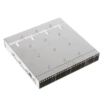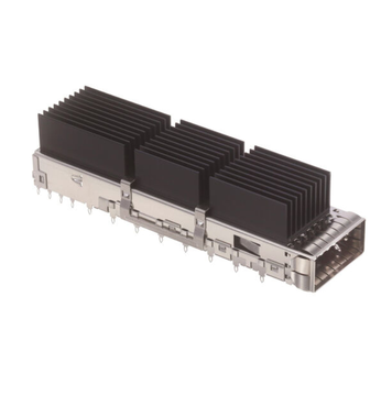
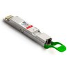
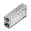
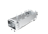
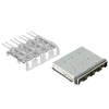

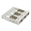

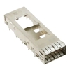
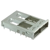
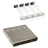
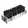


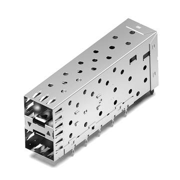



Choosing between an OSFP RHS Cage and a standard OSFP cage depends on the optical module type, mechanical requirements, and cooling design of the host equipment. The main difference is the heatsink arrangement: a standard OSFP module has an integrated heatsink, while an OSFP-RHS module uses a separate riding heatsink installed on the host side.
Although both designs follow the OSFP electrical interface, their mechanical configurations are different. Selecting the wrong cage can cause module insertion problems, insufficient clearance, or an unsuitable thermal arrangement. Understanding their structural differences helps equipment designers and procurement teams make a more informed selection.
Understanding OSFP RHS Cage and Standard OSFP Cage Differences
Both cage types provide a mechanical interface for installing OSFP optical modules in network equipment. They help position the module, secure it in place, and connect it to the host electrical connector. However, their structures are designed around different module housings and heatsink arrangements.
Basic Design and Heatsink Placement
A standard OSFP cage accommodates an optical module with an integrated heatsink. The heatsink is attached to the module housing and moves with the transceiver during insertion and removal.
Heat generated by the module's internal components passes through its housing to the integrated heatsink. Airflow around the heatsink then helps remove heat from the module.
An OSFP RHS Cage accommodates a different module design. The OSFP-RHS module does not have an integrated heatsink on its top. Instead, a separate riding heatsink is installed on the host side and makes thermal contact with the module after insertion.
This arrangement separates the optical module from the main heatsink structure. Equipment manufacturers can therefore design the host-side cooling assembly according to their system requirements.
Key Differences at a Glance
The following table summarizes the main differences between the two cage configurations.
| Feature | Standard OSFP Cage | OSFP RHS Cage |
| Compatible Module | Standard OSFP | OSFP-RHS |
| Heatsink Location | Integrated into the module | Mounted on the host side |
| Module Height | Approximately 13mm, including heatsink | 9.5mm without integrated heatsink |
| Thermal Arrangement | Module-level heatsink | Separate riding heatsink |
| Mechanical Structure | Standard OSFP design | Dedicated RHS design |
| Electrical Interface | OSFP interface | OSFP interface |
| Mechanical Interchangeability | Not directly interchangeable with RHS | Not directly interchangeable with standard OSFP |
The main distinction is not the data transmission rate but the way each design accommodates the optical module and its cooling components.
Why Cage Type Matters for Equipment Design
The cage affects more than the physical installation of an optical transceiver. It also determines how the module is positioned within the host equipment and how much space is available for surrounding components.
For example, a standard OSFP design needs sufficient clearance for the heatsink attached to the module. An RHS configuration places the separate heatsink on the host side, so equipment designers must consider its mounting position and thermal contact area.
These differences should be considered during the early stages of equipment development. Changing the cage configuration after the PCB, front panel, and cooling structure have been finalized may require additional mechanical adjustments.
For procurement teams, understanding the required configuration also makes it easier to identify the correct product specification before requesting a quotation.
Module Compatibility: OSFP RHS Cage vs. Standard OSFP Cage
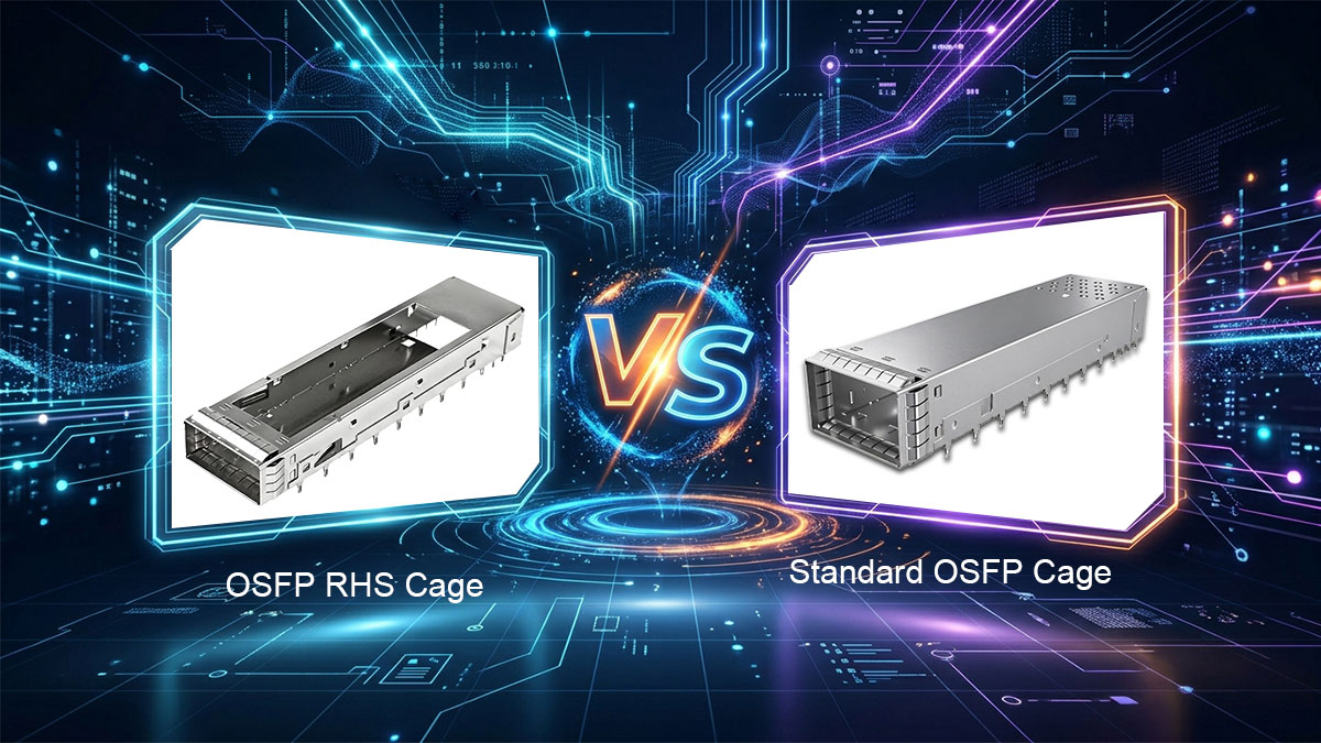
An OSFP RHS Cage is designed for OSFP-RHS modules, while a standard OSFP cage is intended for standard OSFP modules. Although both use the OSFP electrical interface, their mechanical designs are different and do not allow direct interchangeability.
Matching Modules to Cage Types
The first step in compatibility checking is identifying the optical module form factor specified for the host equipment.
Standard OSFP and OSFP-RHS modules have different upper structures because they use different heatsink arrangements.
- Standard OSFP Module: Has an integrated heatsink and requires a matching standard OSFP cage.
- OSFP-RHS Module: Has no integrated heatsink and is designed for a dedicated RHS cage with a host-side riding heatsink.
The module housing, cage structure, and heatsink arrangement must work together as one assembly. A matching electrical interface alone does not guarantee that the transceiver can be installed correctly.
For equipment manufacturers developing a new platform, the supported module form factor should be confirmed before finalizing the cage and front-panel design.
Can the Two Cage Types Be Interchanged?
No. A standard OSFP cage and an OSFP RHS Cage are not directly interchangeable.
One important reason is the position of the forward stop. This mechanical feature controls how far the optical module can enter the cage and helps establish its correct position relative to the electrical connector.
The RHS design uses a different forward-stop position to match its module structure. This prevents an incompatible module from reaching an incorrect insertion position.
The same consideration applies to replacement projects. A cage that appears similar in overall shape may still have a different internal mechanical reference.
Before replacing an existing cage, confirm:
- The module form factor supported by the equipment.
- The forward-stop position specified for the cage.
- The applicable OSFP mechanical specification.
- The required module and heatsink configuration.
Do not assume that a cage can replace another version simply because both products use the same electrical interface.
Common Module Compatibility Mistakes
Compatibility problems often occur when buyers focus on electrical specifications but overlook mechanical requirements.
| Common Mistake | Why It Matters |
| Assuming the same electrical interface means the modules are interchangeable | Electrical compatibility does not guarantee mechanical fit. |
| Using an RHS module in a standard OSFP cage | Different mechanical stop positions can prevent correct insertion. |
| Selecting a cage without checking the heatsink arrangement | The cooling components may not fit or make proper thermal contact. |
| Ignoring module generation | Different OSFP generations may have additional mechanical requirements. |
Another important consideration is the OSFP generation. OSFP-RHS, OSFP800-RHS, and OSFP1600-RHS configurations should be checked against their applicable specifications.
Some combinations may allow physical insertion without guaranteeing mechanical reliability. Therefore, it is important to confirm the exact module generation and corresponding cage requirements rather than relying on appearance or electrical interface alone.
Thermal Performance of OSFP RHS Cage vs. Standard OSFP Cage
The main thermal difference between these designs is how heat moves from the optical module to the host cooling system. A standard OSFP module transfers heat through its integrated heatsink, while an RHS module uses a separate riding heatsink.
Both arrangements are intended to maintain the optical module within its specified operating temperature. However, their actual cooling performance depends on several factors, including thermal contact, heatsink structure, and available airflow.
Differences in Heat Transfer Paths
The two configurations use different heat transfer paths.
Standard OSFP:
Internal Components → Module Housing → Integrated Heatsink → Airflow
OSFP RHS:
Internal Components → Module Housing → Thermal Interface → Riding Heatsink → Cooling System
In the standard design, the heatsink is part of the optical module. Heat passes through the module housing and reaches the heatsink attached to its upper surface.
In the RHS arrangement, the host equipment provides a separate heatsink. The module transfers heat through its upper contact surface into the riding heatsink.
This arrangement gives equipment designers more control over the location and structure of the main cooling component. It can also make it easier to integrate the optical module's cooling path with a shared host-side thermal solution.
Thermal Contact and Heat Dissipation
For an RHS design, proper contact between the module and riding heatsink is essential. Poor contact can increase thermal resistance and reduce heat transfer efficiency.
Several factors influence this connection.
- Contact Surface: The mating surfaces should meet the specified flatness and finish requirements. Uneven surfaces can create small gaps that reduce effective contact.
- Thermal Interface Material (TIM): A suitable thermal pad or interface material can help fill small gaps between the module and heatsink surfaces.
- Contact Pressure: The riding heatsink needs consistent contact pressure to maintain an effective thermal connection.
- Heatsink Design: Material, surface area, and fin structure influence how heat is transferred and released.
These factors should be considered together during equipment development. A larger heatsink does not automatically provide better cooling if the thermal interface or contact pressure is inadequate.
For standard OSFP modules, the integrated heatsink also requires an appropriate thermal design. Its contact with the module housing, fin structure, and surrounding airflow all influence the final result.
Airflow Requirements and Cooling Limitations
Airflow plays an important role in removing heat from both configurations, especially in equipment that uses forced-air cooling.
For standard OSFP modules, airflow needs to pass around the integrated heatsink. The heatsink fin arrangement, airflow direction, and available space can affect how effectively heat is removed.
For RHS configurations, the host-side heatsink must release the heat transferred from the module. Depending on the equipment design, this can involve forced airflow across the riding heatsink or another suitable cooling method.
Common cooling limitations include:
- Restricted airflow around densely arranged optical ports.
- Insufficient clearance between heatsink fins and nearby components.
- Poor thermal contact between the module and riding heatsink.
- High ambient temperatures.
- Inadequate chassis airflow or cooling capacity.
These limitations show why cooling performance should not be judged by heatsink size alone. The complete thermal path needs to be considered.
Factors Affecting Actual Cooling Performance
Neither cage configuration guarantees better thermal performance in every application. The final result depends on how the optical module, heatsink, cage, and host cooling system work together.
Before finalizing the thermal design, equipment engineers should evaluate the following factors.
| Design Factor | What to Check |
| Module Power | Confirm maximum power consumption and thermal requirements. |
| Heatsink Configuration | Evaluate dimensions, material, and cooling structure. |
| Thermal Interface | Verify contact quality and interface requirements. |
| Airflow | Check airflow direction, volume, and available space. |
| Operating Temperature | Ensure the complete system meets the module's specified temperature limits. |
These checks become particularly important in high-density equipment, where multiple optical modules generate heat within a limited chassis space.
The most suitable configuration is the one that meets the module's thermal requirements under the actual operating conditions of the host equipment.
Mechanical Differences Between OSFP RHS Cage and Standard OSFP Cage
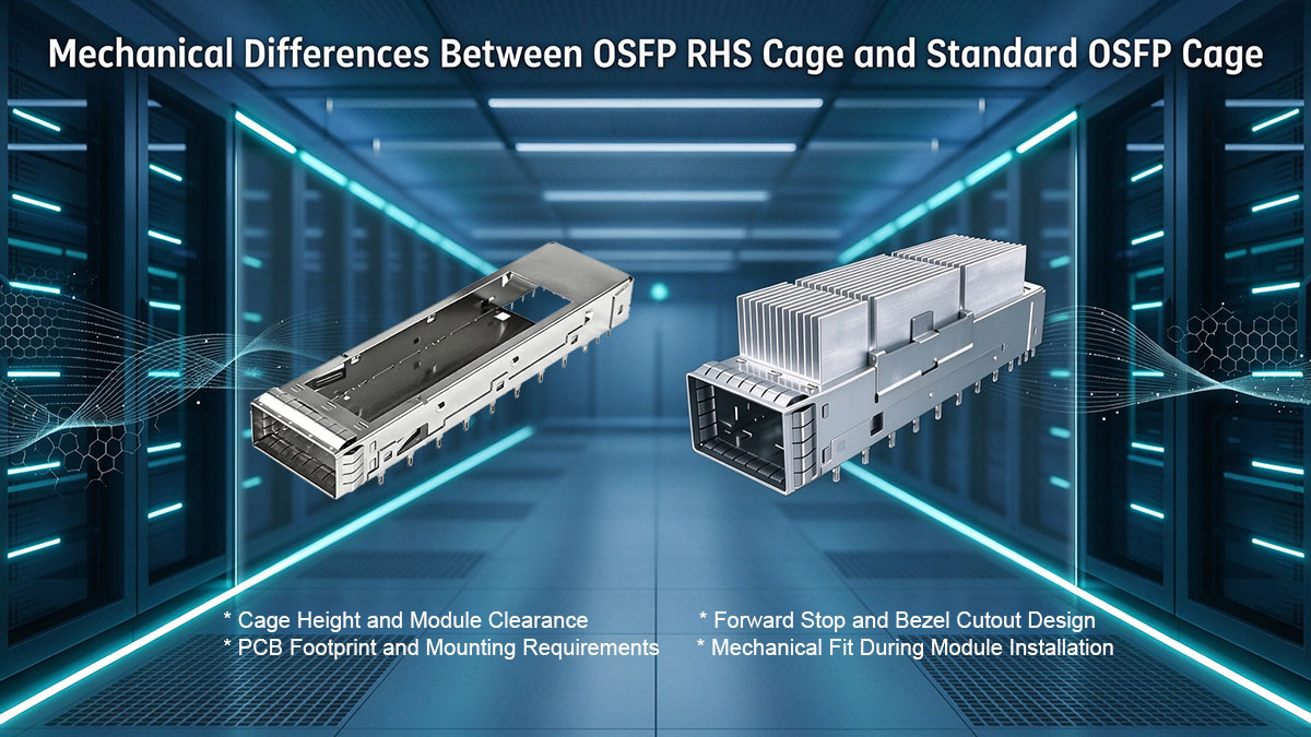
The two cage designs have different mechanical profiles and positioning features. Although they share the same host PCB footprint under the OSFP MSA specification, their overall structures are not directly interchangeable.
Cage Height and Module Clearance
Cage height affects how the optical module fits into the host equipment and how much space remains for cooling components.
A standard OSFP cage accommodates a module with an integrated heatsink. The cage and surrounding equipment must provide sufficient clearance for the complete module assembly.
The RHS version accommodates a lower-profile module without an integrated heatsink. Its separate riding heatsink is positioned above the module on the host side.
When reviewing the mechanical design, pay attention to the following details:
- Cage Height: Confirm the dimensions required by the selected module form factor.
- Heatsink Clearance: Allow sufficient space for the riding heatsink and its mounting structure.
- Component Spacing: Prevent interference with nearby components and assemblies.
- Insertion Clearance: Provide enough space for module installation and removal.
These dimensions should be checked against the complete equipment assembly rather than the cage alone.
Forward Stop and Bezel Cutout Design
The forward stop controls the insertion depth of the optical module and helps establish its position relative to the electrical connector.
The RHS and standard OSFP designs use different forward-stop positions to match their corresponding module structures. This difference is an important part of their mechanical compatibility requirements.
The bezel cutout is another important design feature. It refers to the opening in the equipment's front panel through which the optical module is accessed.
An unsuitable opening can affect the cage's position relative to the panel and create problems during assembly.
When reviewing mechanical drawings, check:
- Forward-stop position and reference dimensions.
- Bezel opening height and width.
- Cage-to-panel alignment.
- Clearance around the module insertion area.
Correct alignment helps ensure that the cage assembly fits the front panel and that the optical module can be accessed as intended.
PCB Footprint and Mounting Requirements
The OSFP RHS and standard OSFP cage designs share the same host PCB footprint according to the MSA specification. However, this does not mean that every mounting detail or surrounding mechanical structure is identical.
Before PCB integration, verify the following items.
| Design Consideration | What to Verify |
| PCB Footprint | Confirm positioning pins and mounting locations. |
| Mounting Type | Check the specified mounting method, such as Press-Fit or SMT. |
| Soldering Area | Verify pad dimensions and assembly requirements. |
| Connector Alignment | Ensure the electrical connector matches the cage position. |
| Component Keep-Out | Leave sufficient clearance around mounting areas. |
The mounting arrangement should also match the PCB design and manufacturing process. This is particularly important in multi-port equipment, where several cages and connectors must be aligned within a limited board area.
For an existing PCB design, check the complete mechanical drawing before assuming that a different cage version can be installed without further changes.
Mechanical Fit During Module Installation
A properly matched cage should allow the module to enter smoothly, engage its retention mechanism, and connect correctly with the electrical connector.
The retention mechanism keeps the transceiver in its intended position after insertion. Incorrect alignment or insufficient clearance can make installation difficult or prevent the module from reaching its specified mating position.
Before finalizing the assembly, verify three points:
- Insertion Alignment: The module and cage opening should align correctly during insertion.
- Retention: The latch should engage and hold the module securely.
- Connector Engagement: The module should reach the specified mating position without mechanical interference.
Checking these details with the intended module and cage assembly can help identify mechanical problems before mass production.
Where OSFP RHS Cage and Standard OSFP Cage Fit Best
Standard OSFP cages are suitable for equipment designed around modules with integrated heatsinks, while RHS configurations are intended for systems using host-side riding heatsinks.
The most suitable option depends on the equipment's cooling architecture, available installation space, and supported module type. Different networking environments may therefore require different cage configurations.
Traditional Air-Cooled Network Equipment
Standard OSFP cages are suitable for network switches, routers, and other equipment designed around optical modules with integrated heatsinks and chassis airflow.
This configuration can work well when the equipment already has an established airflow path and sufficient space around the optical ports.
Typical design conditions include:
- Established front-to-back or side-to-side airflow.
- Sufficient clearance around integrated module heatsinks.
- Standard OSFP module support.
- A cooling design based on the module's integrated heatsink.
For equipment already designed around standard OSFP modules, retaining the matching cage configuration can simplify mechanical integration and avoid unnecessary changes to the existing cooling arrangement.
Host-Side Cooling and Cold Plate Integration
RHS configurations are particularly relevant to equipment that uses host-side thermal management, including systems with cold plate cooling.
The separate riding heatsink allows heat to move from the module into a cooling structure installed within the host equipment. A cold plate can be integrated with this structure to transfer heat into a liquid cooling loop.
This approach can be useful when several optical ports need to share a coordinated thermal management solution.
Key design considerations include:
- Thermal Contact: Maintain consistent contact between the module and the riding heatsink.
- Cold Plate Integration: Confirm that the cooling plate matches the cage arrangement and system layout.
- Cooling Loop Design: Check coolant flow, inlet temperature, and heat removal capacity.
- Serviceability: Consider how the cooling assembly affects module replacement and maintenance.
An RHS configuration does not automatically require liquid cooling. Other suitable host-side cooling arrangements can also be used when the complete thermal design meets the module requirements.
The important consideration is whether the host equipment can accommodate the riding heatsink and provide an effective way to remove the transferred heat.
High-Density 800G and 1.6T Systems
As network equipment moves toward 800G and 1.6T optical connectivity, managing heat within limited chassis space becomes increasingly important.
Higher-speed modules can have substantial power requirements. Therefore, equipment designers need to consider module power consumption, port spacing, heatsink dimensions, and available cooling capacity together.
Both standard OSFP and RHS configurations can be used in high-speed networking environments, depending on the host platform's mechanical and thermal design.
| Application Requirement | Standard OSFP Cage | OSFP RHS Cage |
| Standard OSFP module support | Suitable | Not directly compatible |
| OSFP-RHS module support | Not directly compatible | Suitable |
| Integrated module heatsink | Accommodated | Not required |
| Host-side riding heatsink | Not required by default | Required |
| Cold plate integration | Depends on additional host design | Can be integrated into the RHS cooling structure |
| High-speed networking | Depends on platform support | Depends on platform support |
Data rate alone does not determine cage selection. The exact module form factor and host platform specifications must be confirmed first.
For high-density designs, the complete port arrangement should also be reviewed. Multiple optical modules can generate significant heat within a limited area, so the cooling capacity of the entire chassis matters.
Space and Cooling Constraints in Different Equipment
Available space and cooling capacity can influence which configuration is more practical for a particular equipment design.
A standard OSFP module requires clearance for its integrated heatsink and sufficient airflow around the module. This can be convenient when the equipment already has an established cooling arrangement.
An RHS configuration moves the heatsink to the host side, allowing more flexibility in arranging the cooling structure. However, designers must also account for the riding heatsink, contact mechanism, and available host-side clearance.
The following conditions can help guide the decision.
| Equipment Condition | Recommended Consideration |
| Existing standard OSFP platform | Use a matching standard OSFP cage. |
| Host designed for RHS modules | Select a dedicated RHS cage. |
| Integrated liquid cooling system | Evaluate RHS cage and cold plate compatibility. |
| Limited heatsink clearance | Compare complete assembly dimensions. |
| High-density optical ports | Evaluate port spacing and total thermal load. |
The most suitable configuration is the one that meets the complete equipment requirements, rather than simply the one with a smaller module or a different heatsink arrangement.
How to Choose Between OSFP RHS Cage and Standard OSFP Cage
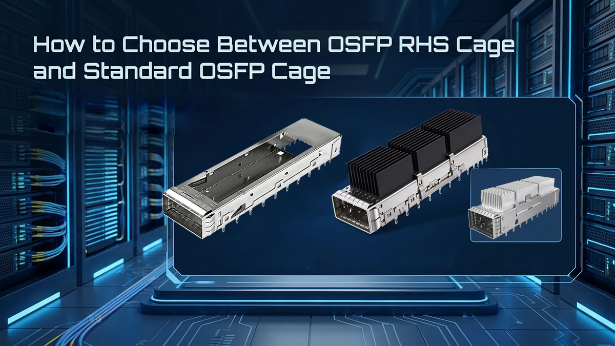
Selecting the right cage starts with identifying the required module form factor and checking the host equipment's design requirements. The following steps provide a practical approach for equipment designers and procurement teams.
Identify the Required Module Form Factor
First, confirm which OSFP module type the host equipment is designed to support.
- Standard OSFP: Select a matching standard cage when the module has an integrated heatsink.
- OSFP-RHS: Select a dedicated RHS cage when the module requires a host-side riding heatsink.
- Module Generation: Check the applicable specification, particularly for 800G and 1.6T equipment.
Do not select a cage based on data rate or electrical interface alone. The mechanical form factor must also match.
For replacement projects, identify the exact module currently used in the equipment. A similar-looking module may have a different mechanical configuration, so its specification should be checked before choosing a replacement cage.
Assess the Available Cooling Design
Next, evaluate how the equipment will remove heat from the optical module.
Consider these questions:
- Does the equipment have sufficient airflow around the integrated heatsink?
- Is there enough space for a host-side riding heatsink?
- Does the design require a shared heatsink or cold plate?
- Can the cooling system maintain the module within its specified operating temperature?
The cooling arrangement should match the module's thermal requirements and the equipment's available space.
If the equipment uses a shared cooling structure, also confirm that the selected cage and heatsink assembly can be integrated into that structure.
Confirm Mechanical Fit with Existing Equipment
A suitable cage must match the host equipment's mechanical layout.
Even when two designs share the same PCB footprint, their overall structures may differ. Compare the proposed cage drawing with the existing equipment specifications.
| Mechanical Item | What to Verify |
| Cage Dimensions | Required height, width, and depth. |
| Forward Stop | Position and compatibility with the module. |
| Bezel Cutout | Front-panel opening and cage alignment. |
| PCB Footprint | Mounting locations and connector positioning. |
| Heatsink Clearance | Space for the complete cooling assembly. |
| Retention Mechanism | Correct module insertion and locking. |
For replacement projects, do not assume that a matching PCB footprint guarantees compatibility with the existing front panel or cooling assembly.
Compare Available OSFP Cage Configurations
After confirming the module type, cooling arrangement, and mechanical requirements, compare available cage configurations to find one that matches your equipment design. Port count, heatsink arrangement, mounting method, and EMI protection are important factors to consider.
LINK-PP offers different OSFP cage configurations for single-port and multi-port applications.
For example, the LP11SC010U0SM is a 1×1 OSFP cage featuring a heatsink configuration, EMI spring fingers, and press-fit termination. It is an option for equipment designs that require a single-port cage with an integrated heatsink structure.
For multi-port layouts, the LP14SC01000 provides a 1×4 OSFP cage configuration with press-fit mounting and EMI shielding. Its four-port arrangement is suitable for PCB designs that integrate multiple OSFP interfaces in one assembly.
When comparing these products, review their mechanical drawings, mounting dimensions, and heatsink arrangements against your equipment requirements.
Both models are standard OSFP cage options, not confirmed dedicated OSFP-RHS cages. Their compatibility with the intended module and host design should be verified before ordering. Do not assume that a standard OSFP cage can accommodate an OSFP-RHS module.
For additional configurations, visit the LINK-PP OSFP Cages & Connectors category to review available products and specifications.
Before placing an order, request the relevant mechanical drawings and confirm that the selected configuration meets your equipment requirements.
OSFP RHS Cage vs. Standard OSFP Cage: Final Considerations

Choosing between these two cage designs comes down to module compatibility, mechanical requirements, and the host equipment's cooling architecture.
A standard OSFP cage is the appropriate choice for equipment designed around optical modules with integrated heatsinks. An RHS configuration is more suitable when the system uses OSFP-RHS modules and requires a separate host-side riding heatsink.
Before making a final selection, consider these key points:
Module Compatibility: Match the cage to the correct OSFP module form factor and generation.
Cooling Design: Consider the required heatsink arrangement and overall thermal solution.
Mechanical Fit: Verify cage dimensions, forward-stop position, bezel cutout, and PCB mounting requirements.
Application Requirements: Evaluate available space, airflow, and any cold plate integration needs.
Product Verification: Review mechanical drawings and confirm the complete assembly before ordering.
Selecting the correct cage early in the equipment design process can help prevent mechanical interference, simplify thermal integration, and reduce compatibility issues during production.
If you are evaluating cage configurations for your next networking project, visit the LINK-PP Official Store to explore available optical transceiver cage products and review their specifications. You can also contact the team to discuss mechanical requirements, request product drawings, and confirm the appropriate configuration before placing an order.