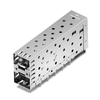
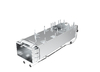
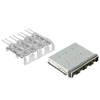

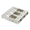

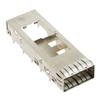
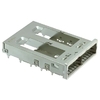
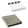
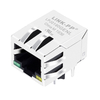
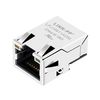
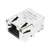
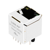
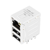
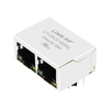
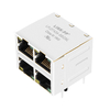
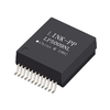
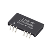
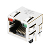
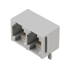




Choosing the right RJ45 MagJack, also known as a magnetic RJ45 connector, requires matching its Ethernet standard, magnetic specifications, PCB footprint, and PoE requirements to your device. Available options range from 10/100BASE-T to 10GBASE-T Ethernet, with different port configurations, mounting styles, and electrical characteristics for various network applications.
For network switches, routers, and industrial equipment, connectors that look similar may still have different pin assignments or internal magnetic configurations. Checking these details before purchasing helps prevent compatibility issues, PCB redesigns, and installation problems.
This RJ45 MagJack selection checklist covers the main product types, electrical and mechanical specifications, and practical purchasing considerations. It also introduces suitable LINK-PP RJ45 connectors for different Ethernet applications, helping you compare available options and make an informed purchasing decision.
What Is an RJ45 MagJack and How Does It Work?
An RJ45 MagJack, also called a magnetic RJ45 jack, is an Ethernet connector that combines a standard RJ45 interface with built-in magnetic components, such as isolation transformers and common-mode chokes. These components help provide electrical isolation, reduce unwanted noise, and support reliable signal transmission between Ethernet cables and network devices.
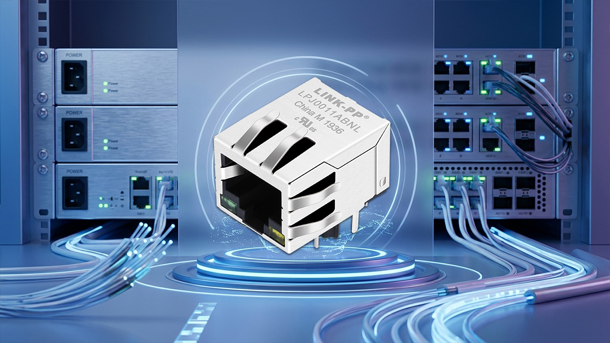
In a conventional Ethernet design, a standard RJ45 jack is often used with separate magnetic components mounted elsewhere on the PCB. An integrated MagJack combines the connector and magnetics in one assembly. This RJ45 with magnetics design is commonly used in Ethernet switches, routers, industrial controllers, network interface cards, and other communication equipment.
Understand the Basic Structure of an RJ45 MagJack
An integrated magnetic connector combines several components into one compact assembly. Each component has a specific role in the Ethernet connection.
The main components typically include:
| Component | Function |
| RJ45 Modular Jack | Provides the physical interface for connecting Ethernet cables. |
| Isolation Transformer | Provides electrical isolation between the Ethernet PHY and the cable side. |
| Common-Mode Choke (CMC) | Helps suppress common-mode noise and reduce electromagnetic interference (EMI). |
| LED Indicators (Optional) | Display link status and network activity. |
| Metal Shield (Optional) | Provides shielding against external electromagnetic interference. |
Not every RJ45 MagJack includes the same components. LED indicators and metal shielding are optional, while the internal magnetic configuration depends on the Ethernet standard and product design. Always check the datasheet to confirm what is included in a specific model.
Learn How Integrated Magnetics Support Ethernet Connections
The integrated magnetics sit between the Ethernet PHY chip and the network cable. They help transfer Ethernet signals while managing electrical isolation and unwanted noise.
1. Isolation Transformer
An isolation transformer transfers Ethernet signals through magnetic coupling without a direct electrical connection between the PHY and cable sides. This helps reduce the effects of ground potential differences and provides electrical isolation.
2. Common-Mode Choke (CMC)
A common-mode choke reduces unwanted noise that affects signal lines in the same direction. By suppressing this common-mode interference, it helps improve electromagnetic compatibility (EMC) and reduce noise affecting nearby circuits.
These components work together to support signal integrity, although their exact configuration depends on the connector design and Ethernet requirements.
Identify the Main Benefits of an Integrated MagJack
Combining the connector and magnetic components into one assembly offers several practical advantages for Ethernet equipment manufacturers, particularly when board space and assembly efficiency are important.
1. Saves PCB Space
Integrating the magnetics into the connector reduces the need for separate transformer and choke components on the PCB. This is useful for compact devices and high-density network equipment.
2. Simplifies PCB Design
With fewer separate components to place and route, engineers can simplify the Ethernet interface layout and reduce the number of individual assembly steps.
3. Simplifies Component Sourcing
Using an integrated connector reduces the need to purchase and manage separate magnetic components. This can make sourcing and assembly planning easier for equipment manufacturers.
4. Offers Flexible Interface Options
Depending on the model, integrated connectors are available with different port counts, LED configurations, shielding options, and PoE support. This gives designers more flexibility when developing network equipment.
These advantages make integrated magnetic connectors a practical option for network devices where PCB space, design simplicity, and interface integration are important.
Understand the Difference Between MagJack and Separate Magnetics
An integrated magnetics RJ45 connector combines the jack and magnetic components in one assembly. Another option is to use a standard RJ45 jack with separate LAN transformers and common-mode chokes mounted elsewhere on the PCB.
Both designs provide Ethernet connectivity, but their component arrangements and design considerations are different.
| Comparison | Integrated MagJack | Separate Magnetics |
| Component Structure | Connector and magnetics combined | Connector and magnetics installed separately |
| PCB Layout | More integrated design | Requires additional PCB space |
| Component Count | Generally lower | Generally higher |
| Design Flexibility | Magnetic configuration is predefined | Individual magnetic components can be selected |
| Assembly | Fewer separate components to install | More individual components to assemble |
| Maintenance | Entire assembly may need replacement | Individual components can be replaced separately |
Which design is better?
An integrated solution is often suitable for compact Ethernet devices, multi-port switches, and designs that prioritize simpler PCB layouts.
A separate magnetic design may be more suitable when engineers need greater flexibility to select individual transformers and chokes or customize the circuit layout.
The right option depends on the device architecture, electrical requirements, available PCB space, and manufacturing considerations. Neither design is automatically better for every application.
What Are the Different Types of RJ45 MagJacks?
RJ45 MagJacks are available in different configurations to meet the needs of various Ethernet devices and network applications. They differ in transmission speed, port count, PoE support, mounting style, and additional features such as shielding and LED indicators.
Understanding these options makes it easier to narrow down suitable products before comparing their technical specifications. The following sections introduce the most common types and their typical applications.
Compare RJ45 MagJack Options by Ethernet Speed
Ethernet speed is one of the first factors to consider when comparing integrated magnetic connectors. Different models support different data rates, ranging from basic Fast Ethernet to high-speed 10 Gigabit Ethernet.
Common speed options include:
| Ethernet Type | Data Rate | Typical Applications |
| 10/100BASE-T | 10/100 Mbps | Industrial controllers, basic network devices |
| 1000BASE-T | 1 Gbps | Network switches, routers, servers |
| 2.5GBASE-T | 2.5 Gbps | Wi-Fi access points, enterprise networks |
| 5GBASE-T | 5 Gbps | High-speed wireless access points, network equipment |
| 10GBASE-T | 10 Gbps | Servers, high-speed switches, data center equipment |
Not every product supports all Ethernet speeds. Always check the manufacturer's specifications to confirm that the selected connector supports the intended network standard.
Choose Single-Port or Multi-Port RJ45 MagJack Designs
These connectors are also available in different port configurations. The right choice depends on how many Ethernet connections the device needs and how much PCB space is available.
The most common configurations include:
| Port Configuration | Structure | Typical Applications |
| 1×1 | One port | Industrial controllers, embedded devices |
| 1×2 | Two ports in one row | Network appliances, compact switches |
| 1×4 | Four ports in one row | Ethernet switches, network equipment |
| 1×N | Multiple ports in one row | Multi-port network devices |
| 2×N | Two rows of stacked ports | High-density Ethernet switches |
There are two common multi-port arrangements:
- Ganged Design: Multiple RJ45 ports are arranged side by side in a single row. This layout is commonly used in network switches and communication equipment.
- Stacked Design: Ports are arranged in two or more vertical rows, allowing more Ethernet interfaces to fit within a limited front-panel area.
Compare PoE, PoE+, and PoE++ MagJack Options
Power over Ethernet (PoE) allows compatible network devices to receive electrical power and transmit data through the same Ethernet cable. This eliminates the need for a separate power connection in many applications.
Depending on the power requirements, integrated magnetic connectors are available in different PoE configurations.
| PoE Type | IEEE Standard | Maximum PSE Output Power | Typical Applications | Maximum PD Power |
| Non-PoE | Not applicable | — | Standard Ethernet connections | — |
| PoE | IEEE 802.3af | 15.4W | IP cameras, basic wireless access points | 12.95W |
| PoE+ | IEEE 802.3at | 30W | Advanced wireless access points, IP cameras | 25.5W |
| PoE++ Type 3 | IEEE 802.3bt | 60W | High-power wireless access points, network devices | 51W |
| PoE++ Type 4 | IEEE 802.3bt | 90W | High-power network and connected devices | 71.3W |
PSE output power is the maximum power supplied by the switch or injector. The maximum power available at the PD is lower because of losses in the Ethernet cable. For IEEE 802.3bt Type 4, the standard maximum is 90W at the PSE and 71.3W at the PD.
When comparing these products, distinguish between Non-PoE and PoE-compatible designs. A connector designed for standard Ethernet data transmission does not automatically support power delivery.
PoE applications also require suitable magnetic components and current-handling capabilities. Therefore, check the manufacturer's datasheet to confirm the supported PoE standard and power requirements.
Understand THT, SMT, and Different Mounting Orientations
Mounting style describes both how the connector attaches to the PCB and how its Ethernet port faces the equipment enclosure.
THT and SMT describe how the connector is mounted to the PCB, while right-angle and vertical describe the direction of the Ethernet port. These are separate design characteristics. The table below compares the options.
| Design | Main Characteristic | Common Application |
| THT | Pins pass through PCB holes | Traditional network equipment |
| SMT | Mounted on PCB surface pads | Compact electronic devices |
| Right-Angle | Horizontal port orientation | Front-panel Ethernet interfaces |
| Vertical | Top-entry port orientation | Vertical PCB layouts |
Choose the option that fits the PCB and enclosure layout; the mechanical drawing remains the reference for final dimensions and mounting details.
Explore Shielded, Unshielded, and LED Configurations
In addition to speed and port configuration, these products offer different shielding and LED options to meet specific equipment requirements.
1. Shielded vs. Unshielded Designs
- Shielded MagJack: Features a metal housing or shield structure that helps control electromagnetic interference. It is commonly used in equipment with stricter EMI requirements.
- Unshielded MagJack: Does not include the same metal shielding structure and may be suitable for designs where additional connector shielding is not required.
The choice depends on the equipment's EMC requirements, PCB grounding design, and cable configuration.
2. LED and Non-LED Designs
LED indicators provide a convenient way to check Ethernet connection status without additional monitoring equipment.
Common options include:
- With LED: Uses built-in indicators to display link status or network activity.
- Without LED: Provides a simpler interface for equipment that does not require visual status indicators.
- Single-Color LED: Uses one color for a specific status indication.
- Dual-Color LED: Uses different colors to indicate different connection or activity states.
For example, network switches often use LED-equipped connectors to help technicians identify active ports and troubleshoot connection issues.
The right combination depends on the equipment's EMC design and whether technicians need visible port-status information.
What Specifications Matter When Choosing an RJ45 MagJack?
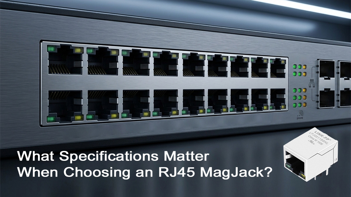
After understanding the different types, the next step is to compare their technical specifications. Two products may have similar appearances and port configurations but differ in electrical performance, PHY compatibility, power handling, and operating temperature.
Before selecting a model, check the following specifications to make sure it meets your device requirements and works with the existing Ethernet design.
Check Ethernet Speed and Data Rate Requirements
Start by checking the Ethernet standard and speed supported by your equipment's PHY chip. The selected connector should match the required transmission mode rather than simply offering a higher data rate.
Review these points before selecting a model:
- Current Network Requirements: Identify the actual connection speed needed by your device, such as 100Mbps, 1Gbps, or 10Gbps.
- Future Network Upgrades: If the equipment may support higher speeds in the future, consider whether the PCB design and PHY chip can accommodate the upgrade.
The supported data rate depends on the complete Ethernet design, including the PHY, magnetics, PCB layout, and cabling. A higher-rated connector alone cannot increase the network speed.
Verify Electrical Specifications and Isolation Requirements
Electrical specifications help determine whether the internal magnetic components are suitable for your Ethernet circuit. These parameters affect signal transmission, noise performance, and electrical isolation.
The following specifications are worth checking in the product datasheet:
| Parameter | What It Means | Why It Matters |
| Turns Ratio | The ratio between transformer windings | Helps match the PHY and cable-side electrical requirements |
| OCL (Open Circuit Inductance) | Inductance measured with the secondary winding open | Helps maintain signal performance, especially at low frequencies |
| Insertion Loss | Signal power lost when passing through the magnetics | Lower loss helps preserve signal strength |
| Return Loss | The amount of signal reflected back toward the source | Helps evaluate impedance matching |
| Crosstalk | Unwanted signal coupling between nearby channels | Lower crosstalk helps reduce interference |
| CMRR | Common-Mode Rejection Ratio | Indicates how effectively common-mode signals are rejected |
| Isolation Voltage | Voltage the insulation system can withstand under specified test conditions | Helps verify electrical isolation requirements |
One important point is that these values should not be evaluated separately from the Ethernet PHY requirements. For example, the turns ratio and OCL must match the intended circuit design, while insertion loss and return loss should meet the requirements across the operating frequency range.
Always compare the datasheet values with the PHY manufacturer's recommended magnetic specifications or reference design. There is no single set of electrical values suitable for every Ethernet application. Not every manufacturer uses the same parameter names or test conditions, so compare the measurement conditions as well as the values.
Check Compatibility with Your Ethernet PHY Chip
The Ethernet PHY chip controls the physical transmission and reception of network signals. The magnetic connector sits between the PHY and the external Ethernet cable, so both components need to work together.
Even if two MagJacks support the same Ethernet speed, they may not have the same internal magnetic configuration or electrical characteristics.
Before choosing a model, check the following information:
- PHY Manufacturer and Part Number: Identify the exact PHY chip used in your equipment.
- Reference Design: Check the magnetic connector or transformer recommended in the PHY manufacturer's reference circuit.
For example, if your device uses a particular Ethernet PHY, consult its reference design to identify the recommended magnetics or approved component characteristics. Use that information when reviewing candidate products.
If you are replacing an existing model, provide the original part number and PHY information to the supplier. This makes it easier to identify a suitable alternative and reduce compatibility risks.
Confirm PoE Power Ratings and Current Requirements
If your Ethernet device uses Power over Ethernet (PoE), the magnetic connector must also meet the power delivery requirements.
In a PoE design, the magnetic components carry data signals while also handling current from the power-sourcing circuit. Their electrical and thermal limits therefore need to suit the intended power level.
Before selecting a PoE-compatible model, check these details:
| Specification | What to Check |
| PoE Standard | IEEE 802.3af, 802.3at, or 802.3bt |
| Current Rating | Whether the magnetic components support the required operating current |
| Voltage Rating | Whether the product meets the system's PoE voltage requirements |
| Winding Configuration | Whether the internal transformer connections support the intended power arrangement |
| Temperature Rise | Whether the connector can handle the additional heat generated during operation |
For example, a device designed for PoE+ should use a connector with suitable current-handling capabilities and a magnetic configuration that supports the intended power arrangement.
Confirm that the datasheet explicitly identifies the required PoE standard and power configuration; Ethernet speed alone does not establish PoE capability.
Consider Operating Temperature and Application Environment
The operating temperature range is another important specification, especially for equipment installed in industrial or outdoor environments.
Different applications expose network devices to different temperature conditions. A connector suitable for an office switch may not be appropriate for equipment installed in an outdoor cabinet or factory environment.
Common operating temperature ranges found in product datasheets include:
| Common Product Range | Typical Operating Range | Common Applications |
| Commercial Range | 0°C to +70°C | Office switches, routers, indoor network equipment |
| Extended Range | -40°C to +85°C | Industrial controllers, outdoor communication devices |
These are common ranges found in product specifications, not universal definitions for all manufacturers. Always confirm the operating temperature listed in the selected model's datasheet.
You should also consider the actual installation environment, including:
- Ambient temperature around the equipment.
- Heat generated by nearby electronic components.
- Airflow and ventilation inside the enclosure.
- Additional heat from PoE power transmission, if applicable.
For industrial or outdoor equipment, consider both ambient temperature and internal heat when selecting a connector with a suitable operating temperature range.
What Mechanical Details Should You Check for an RJ45 MagJack?
Electrical specifications are only part of the selection process. The physical design of an RJ45 MagJack also needs to match your PCB layout and equipment enclosure.
Even when two products support the same Ethernet speed, their dimensions, pin arrangements, and mounting structures may be different. Checking these mechanical details before ordering helps avoid installation problems and unnecessary PCB changes.
Verify PCB Footprint and Pin Configuration
The PCB footprint defines the position and size of the pads or holes used to mount the connector. The pin configuration determines how its electrical terminals connect to the PCB circuit.
These details are especially important when replacing an existing MagJack or selecting a compatible alternative.
Before making a decision, check the following:
- Pin Layout: Compare the number and positions of all connector pins with the PCB design.
- Pin Pitch: Confirm the distance between adjacent pins matches the PCB footprint.
- Hole and Pad Dimensions: Check the required hole diameters for through-hole designs or pad sizes for surface-mount products.
- Pin Assignment: Verify that signal pins, transformer center taps, LED connections, and shield terminals match the circuit requirements.
Do not assume that two connectors with similar external dimensions have the same pinout. Even a small difference in terminal positions can make a replacement incompatible with the existing PCB.
Check Port Count and Connector Dimensions
The number of Ethernet ports and the overall connector dimensions affect how the MagJack fits into the equipment enclosure.
For multi-port network devices, the distance between adjacent ports is also important. Incorrect spacing may prevent proper alignment with the front panel or create installation difficulties.
Pay attention to these mechanical details:
- Overall Width and Height: Make sure the connector fits within the available PCB and enclosure space.
- Port Spacing: Check the distance between adjacent RJ45 interfaces.
- Port-to-Panel Alignment: Confirm that the RJ45 openings align with the equipment's front panel and PCB position.
- Connector Depth: Check whether the connector fits within the available space behind the front panel.
For high-density Ethernet equipment, compare the manufacturer's mechanical drawing with your PCB layout and front-panel dimensions to ensure proper installation.
Select the Correct Tab-Up or Tab-Down Orientation
RJ45 connectors are available with different latch orientations, commonly known as Tab-Up and Tab-Down.
The tab is the small locking clip on an Ethernet plug that keeps the cable securely connected to the jack.
- Tab-Up: The locking tab faces upward when the connector is viewed in its specified mounting orientation.
- Tab-Down: The locking tab faces downward in the corresponding orientation.
This difference affects how users insert and remove Ethernet cables, especially when several ports are installed close together.
When selecting a replacement, compare the latch orientation with the original connector and equipment front-panel design. Choosing the wrong orientation may make cable access difficult or prevent the connector from fitting the intended opening.
Also check the connector drawing carefully, since viewing direction and drawing orientation can affect how Tab-Up and Tab-Down are represented.
Confirm Shielding, LED Position, and Mounting Type
The external structure also includes details such as the metal shield, LED windows, and mounting supports. These features affect the physical fit and integration of the connector into the equipment.
Consider the following points:
1. Shielding Structure
Check the shape and dimensions of the metal shield, including its grounding tabs and mechanical contact points. These details should match the PCB grounding layout and enclosure design.
2. LED Position
If the connector includes status indicators, verify their location, viewing direction, and light-window arrangement. The LEDs should align with the equipment's front-panel openings so that users can easily see the connection status.
3. Mounting Supports
Some models include additional mounting pegs or mechanical supports to improve stability during installation. Check their positions and dimensions against the PCB design.
4. Connector Profile
Compare the overall connector height and shape with the available enclosure space. Low-profile designs may be useful when the equipment has limited internal clearance.
These details may seem minor, but they can affect cable access, assembly, and the final appearance of the network device.
Use the manufacturer's mechanical drawing to compare the connector against the PCB layout and enclosure before approving the design.
Which LINK-PP RJ45 MagJack Is Right for Your Application?
Different Ethernet devices have different interface requirements, so there is no single MagJack suitable for every application. LINK-PP offers integrated RJ45 connectors with different data rates, port configurations, PoE options, and mechanical designs.
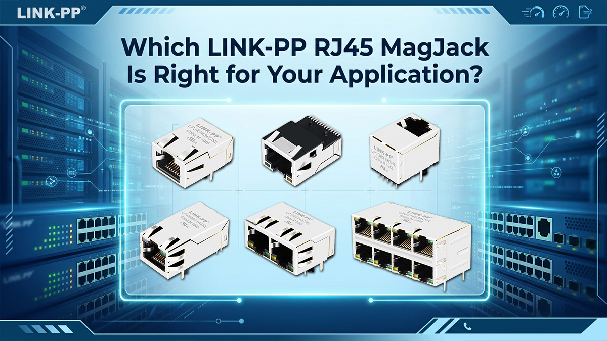
Whether you are developing an industrial controller, network switch, router, or high-speed communication device, choosing a product based on its actual application requirements can help narrow down the available options.
Here are some LINK-PP RJ45 MagJack options worth considering for different Ethernet applications.
Explore LINK-PP MagJacks for Fast Ethernet Applications
For devices that only require basic Ethernet connectivity, a 10/100BASE-T MagJack is often a practical choice. These connectors are suitable for equipment that does not need Gigabit or multi-gigabit data transmission.
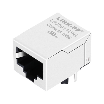
One example is the LINK-PP LPJ0011DNL, a single-port RJ45 MagJack designed for 10/100BASE-T Ethernet applications.
Its main features include:
- Data Rate: 10/100BASE-T
- Port Configuration: 1×1 single port
- Mounting Type: Through-Hole (THT)
- Latch Orientation: Tab Down
- LED: No LED
- PoE: Non-PoE
- Operating Temperature: 0°C to +70°C
This model is suitable for applications such as solar inverters, game controllers, and digital cameras that require standard Fast Ethernet connectivity.
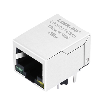
For applications that require visible network status indicators, LINK-PP also offers other 10/100BASE-T models with built-in LEDs.
Find Gigabit RJ45 MagJacks for Network Equipment
For network devices that require Gigabit Ethernet connectivity, choose a magnetic connector designed for 1000BASE-T applications.
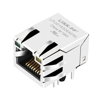
The LINK-PP LPJG16326AENL is a single-port Gigabit RJ45 MagJack designed for network and communication equipment.
Its main specifications include:
- Data Rate: 100/1000BASE-T
- Port Configuration: 1×1 single port
- Mounting Type: Through-Hole (THT)
- Latch Orientation: Tab Up
- LED: Green/Yellow
- Shielding: With EMI Shield Tabs
- PoE: Non-PoE
- Operating Temperature: 0°C to +70°C
This connector is suitable for applications such as digital cameras, routers, automation equipment, and network firewalls.
For equipment operating in industrial environments, it is also worth considering models with an extended temperature range. The temperature rating should match the actual operating conditions of the device.
Choose Multi-Port MagJacks for High-Density Connections
Network switches and other communication devices often require multiple Ethernet interfaces in a limited front-panel space. In these applications, multi-port magnetic connectors can help simplify interface integration.
The LINK-PP LPJG67537A8NL-2 is a 2×6-port Gigabit RJ45 connector designed for high-density Ethernet equipment.
Key product details include:
- Data Rate: 10/100/1000BASE-T
- Port Configuration: 2×6 stacked ports
- Application: Non-PoE Ethernet
- Mounting Type: Through-Hole (THT)
- LED: Green / Green-Yellow
- Operating Temperature: 0°C to +70°C
With twelve Ethernet ports arranged in two rows, this design is suitable for multi-port network switches and other equipment that requires a high number of Gigabit Ethernet connections.
When selecting a multi-port model, also check the overall dimensions, port spacing, PCB footprint, and front-panel alignment to ensure that it fits your equipment design.
Explore PoE and PoE+ MagJacks for Powered Devices
If your network equipment needs to receive or provide power through Ethernet cables, consider a connector designed for the corresponding PoE application.
For example, the LINK-PP LPJT96282-8AWNL is a single-port 2.5GBASE-T RJ45 connector designed for PoE+ applications.
Its main features include:
- Data Rate: 2.5GBASE-T
- Port Configuration: 1×1 single port
- PoE Support: IEEE 802.3at PoE+
- Mounting Type: Through-Hole (THT)
- Latch Orientation: Tab Up
- LED: Green/Yellow
- Shielding: With EMI Shield Tabs
- Operating Temperature: -40°C to +85°C
This model is suitable for applications such as monitoring systems, network hubs, surgical equipment, and patient-care devices that require 2.5G Ethernet connectivity and PoE+ support.
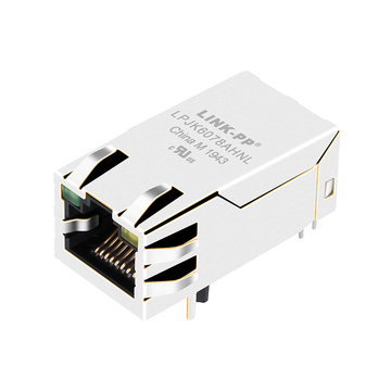
For applications requiring higher power levels, LINK-PP also offers PoE++ models. For example, the LPJK6078AHNL supports 10/100/1000BASE-T Ethernet and PoE++ applications, while the LPJMP96282AGNL combines 10GBASE-T connectivity with IEEE 802.3bt PoE++ support.
Before choosing a PoE model, confirm its supported IEEE standard, power configuration, current rating, and compatibility with your PSE or PD design.
Find Suitable MagJacks for Your Specific Design Requirements
If the models listed above do not match your project, LINK-PP offers additional RJ45 MagJack options for different Ethernet applications and equipment designs.
For new designs or replacement projects, you can provide the original part number, PHY chip information, and application requirements to the LINK-PP technical team. They can help review your specifications and suggest potential product options.
You can also browse the LINK-PP RJ45 Integrated Connector Product Catalog to explore available models and request further product information.
What Should You Check Before Ordering an RJ45 MagJack?
After identifying a suitable model, there are a few practical details to confirm before placing an order. Preparing the necessary product information and understanding the purchasing requirements can help avoid delays during sample evaluation and mass production.
Whether you need a few samples for a new design or a large quantity for ongoing production, the following steps can make the purchasing process easier.
Gather the Information for Your RJ45 MagJack Inquiry
Give the supplier enough information to identify the product or understand the requirements of a new design.
A concise request for quotation (RFQ) can reduce follow-up questions and help the supplier prepare an accurate response.
Include these details in your inquiry:
- Original Part Number: Provide the full part number if you are sourcing a replacement or requesting a specific model.
- Manufacturer and Product Name: Identify the current supplier or the product family, if known.
- Target Application: Briefly describe the equipment and how the connector will be used.
- Estimated Quantity: State whether you need samples, a pilot batch, or regular production volumes.
- Required Schedule: Include any target date for sample evaluation or production delivery.
If you do not have a part number, provide clear photos or a product description. These references can help the supplier understand what you are looking for.
Confirm Technical Specifications and Compatibility
Before placing an order, request the documents your engineering and purchasing teams need to review the product.
Online listings may not include every file required for design approval, incoming inspection, or internal purchasing procedures.
Depending on your project, request the following documents:
- Product Datasheet: Contains the main product specifications and electrical characteristics.
- Mechanical Drawing: Shows the connector dimensions and physical structure.
- 3D CAD or STEP File: Helps engineers check the product's fit within the equipment enclosure.
- PCB Footprint Information: Supports PCB layout and design verification.
- Compliance Documents: Provides relevant information about RoHS, UL, or other applicable requirements.
For replacement projects, ask the supplier to confirm whether the proposed alternative is suitable for your application. A similar-looking product or matching product description does not automatically guarantee a direct replacement.
Ask About Samples, Pricing, and Bulk Orders
For new hardware designs, ordering samples before mass production is a useful way to evaluate the selected connector in your actual application.
Sample testing allows your engineering team to review the product during PCB assembly, equipment integration, and prototype testing.
Before placing an order, discuss the following with the supplier:
1. Sample Availability
Ask whether evaluation samples are available and whether there are any sample charges or shipping costs. Confirm the quantity needed for your prototype testing.
2. Unit Pricing
Request a quotation based on your expected purchase quantity. If you plan to increase production later, ask whether volume-based pricing is available.
3. Minimum Order Quantity (MOQ)
Check the minimum quantity required for each model. This is particularly important when comparing suppliers or purchasing several different connector configurations.
4. Bulk Order Arrangements
For regular production, discuss order quantities, packaging requirements, and possible supply arrangements to support your manufacturing schedule.
Review the quotation for the exact model, quantity, unit price, additional charges, and agreed purchasing terms before approval.
Check Product Availability and Delivery Lead Time
Product availability and delivery schedules are also important, especially when the connector is required for a scheduled production run.
Confirm the following details with the supplier:
- Stock Availability: Check whether the requested model is currently available or needs to be manufactured.
- Production Lead Time: Confirm the estimated manufacturing time for products that are not in stock.
- Sample Delivery: Ask how long sample preparation and shipment are expected to take.
- Shipping Method: Discuss available shipping options and estimated transit times.
- Packaging Requirements: Confirm whether the packaging is suitable for storage, transportation, and your production process.
For repeat orders, it is also helpful to discuss expected demand and purchasing schedules in advance. This allows both sides to plan inventory and production more effectively.
If your project has a fixed launch date, communicate the required delivery date when requesting a quotation rather than waiting until the order is confirmed.
Conclusion: Key Points for RJ45 MagJack Selection
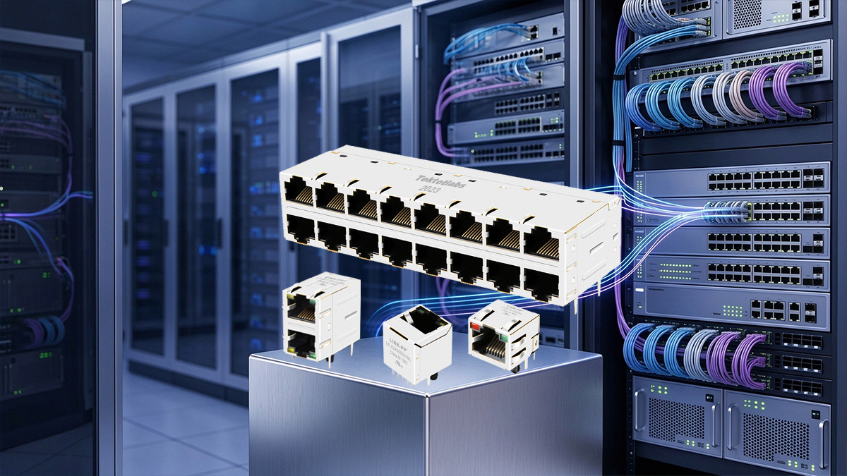
Choosing the right RJ45 MagJack requires more than comparing product appearances or Ethernet speeds. The connector should match your network requirements, electrical design, PCB layout, and operating environment.
Before making a final decision, keep these key points in mind:
- Identify the Ethernet Requirements: Choose a connector that supports the required network standard and data rate.
- Check PHY Compatibility: Compare the magnetic specifications with your Ethernet PHY manufacturer's recommendations.
- Review PoE Requirements: Confirm the supported PoE standard, current rating, and power configuration when needed.
- Verify Mechanical Compatibility: Check the PCB footprint, pin assignment, port dimensions, and mounting orientation.
- Consider the Operating Environment: Select a suitable temperature range and connector configuration for your application.
- Confirm Purchasing Details: Review product documentation, sample availability, pricing, and delivery lead time before ordering.
LINK-PP offers a range of RJ45 MagJack solutions for Fast Ethernet, Gigabit Ethernet, multi-port connections, and PoE applications. Whether you are developing new network equipment or looking for a replacement connector, you can explore different models and compare their specifications to find a suitable option.
Visit the LINK-PP Official Store to explore available RJ45 MagJack products, review product specifications, and find the right connector for your application. If you need help identifying a compatible model or requesting a quotation, contact our sales team for further technical and purchasing support.