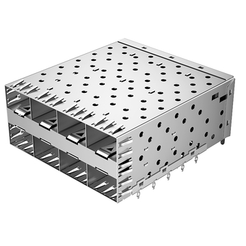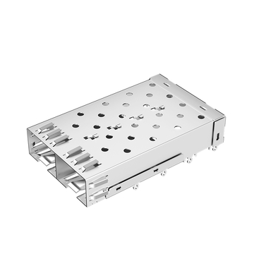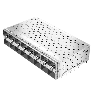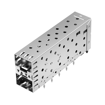
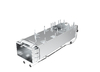
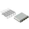

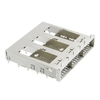

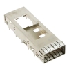
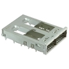
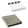
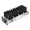


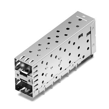



As network equipment continues to support higher bandwidth and more optical interfaces, hardware designers face increasing pressure to maximize front-panel port density without compromising PCB space, thermal performance, or electromagnetic compatibility. SFP cages play an important role in this process by providing mechanical protection, transceiver alignment, and EMI shielding for pluggable optical and copper modules.
However, not all SFP cage assemblies share the same physical structure. Common SFP cage port configurations include 1×1 single-port, 1×N ganged, 2×N stacked, and belly-to-belly designs. Each arrangement offers different advantages in terms of port density, PCB utilization, mechanical integration, and cooling requirements. Understanding these differences is essential when selecting an SFP cage for switches, routers, network interface cards, and other communication equipment.
In this guide, we explain the main SFP cage configurations and their practical applications, covering:
-
The structural characteristics of 1×1, 1×N, and 2×N SFP cages.
-
The differences between ganged, stacked, and belly-to-belly mounting arrangements.
-
PCB layout, mechanical compatibility, EMI shielding, and thermal considerations.
-
How to evaluate LINK-PP SFP Cage options for different hardware designs.
By understanding how these configurations work, engineers can make more informed decisions about port architecture and component integration before finalizing a PCB layout.
What Are SFP Cage Port Configurations?
SFP cage port configurations describe how individual transceiver openings are physically arranged within a cage assembly. The notation typically uses two numbers, such as 1×1, 1×4, or 2×4, to indicate the number of port rows and the number of ports in each row. These arrangements determine how optical interfaces occupy the front panel and integrate with the host PCB.
An SFP cage is a metal enclosure designed to accommodate an SFP or SFP+ transceiver. It works with an electrical connector mounted on the PCB to establish the physical and electrical interface between the pluggable module and the host system. Depending on the design, the cage may be supplied separately or integrated with the electrical connector.
Understanding the 1×1, 1×N, and 2×N Naming Convention
The first number generally represents the number of vertical port rows, while the second represents the number of horizontal positions in each row.
For example:
-
1×1: One row containing one transceiver port.
-
1×2: One horizontal row containing two transceiver ports.
-
1×4: One horizontal row containing four transceiver ports.
-
2×1: Two vertical rows containing one port per row.
-
2×4: Two rows containing four ports per row, for a total of eight ports.
The total number of ports can be calculated by multiplying the two numbers. A 2×4 SFP cage configuration, for example, accommodates eight SFP interfaces.
It is important to distinguish port matrix notation from mounting architecture. A 2×N configuration describes the physical port matrix, while belly-to-belly describes how cage assemblies are mounted on opposite sides of a PCB. These terms are related to hardware layout but do not represent the same structural feature.
Main Types of SFP Cage Configurations
Four common arrangements are particularly relevant to SFP and SFP+ hardware design.
-
1×1 single-port cage: An independent enclosure designed for one SFP transceiver.
-
1×N ganged cage: Multiple transceiver openings integrated into one horizontal metal assembly.
-
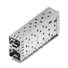
2×N stacked cage: Two vertically arranged port rows integrated into a multi-port assembly.
-
Belly-to-belly arrangement: Two cage assemblies mounted on opposite surfaces of the same PCB.
Each design addresses a different combination of front-panel dimensions, component placement, and system integration requirements. The appropriate choice depends on the equipment architecture rather than port count alone.
Why Port Configuration Matters in Network Hardware Design
SFP cage configuration affects several important aspects of hardware development:
-
Port density: Determines how many optical interfaces can fit within a given front-panel area.
-
PCB utilization: Influences component placement, connector positioning, and available routing space.
-
Mechanical integration: Affects cage alignment with the chassis opening and front-panel bezel.
-
Thermal management: Closely arranged transceivers can create localized heat concentrations.
-
EMI protection: Cage grounding contacts and shielding structures help control electromagnetic emissions.
-
Manufacturing: Different mounting and assembly methods require different PCB footprints and production processes.
Consequently, selecting a cage configuration should be an early part of the mechanical and electrical design process, not simply a component decision made after the PCB layout is complete.
1×1 SFP Cage Configuration: Single-Port Design
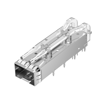
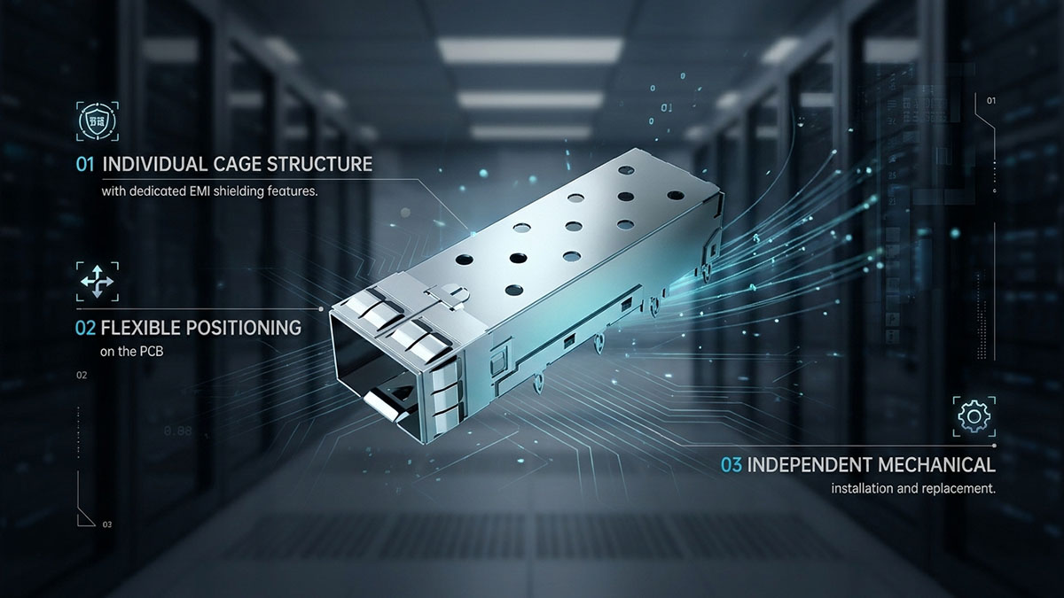
A 1×1 SFP cage is an independent metal enclosure designed to accommodate one SFP transceiver. It provides a straightforward mechanical interface and offers considerable flexibility in PCB placement, making it suitable for equipment that does not require densely integrated multi-port assemblies.
Structure and Design Characteristics of a 1×1 SFP Cage
A standard 1×1 SFP cage consists of a metal housing with one module insertion opening. The cage surrounds the electrical receptacle and provides mechanical guidance when a transceiver is inserted or removed.
Its main structural characteristics include:
-
Single-port enclosure: One independent opening for an SFP or SFP+ module.
-
Metal construction: Commonly manufactured from copper alloy or other conductive materials with suitable surface plating.
-
EMI spring fingers: Conductive contacts help establish grounding continuity between the cage and chassis bezel.
-
Mounting pins: Through-hole press-fit or solder-tail structures secure the cage to the PCB.
-
Optional light pipe: Directs LED indicators toward the front panel in applicable designs.
-
Optional heatsink: Provides an additional thermal management path for compatible transceiver applications.
The cage and electrical connector may be separate components. In this arrangement, the connector is mounted on the PCB first, and the cage is positioned around it.
Some designs also integrate additional features, such as EMI gaskets or dedicated grounding structures, depending on the equipment's shielding requirements.
Advantages and Limitations of the 1×1 Configuration
The main advantage of a single-port cage is its layout flexibility. Because each cage is independent, engineers can position individual interfaces according to specific mechanical and electrical requirements.
Advantages include:
-
Flexible port positioning on the PCB.
-
Straightforward mechanical integration.
-
Independent component placement and assembly.
-
Easier adaptation to customized front-panel layouts.
-
More freedom to distribute ports across different PCB regions.
-
Convenient integration into equipment with a limited number of optical interfaces.
However, this configuration also has limitations when a design requires many ports.
Potential limitations include:
-
Lower port density compared with ganged or stacked assemblies.
-
More individual cage components for multi-port designs.
-
Increased component placement and alignment operations.
-
More PCB space consumed by gaps between independently positioned cages.
-
Greater cumulative mechanical tolerance considerations across multiple ports.
For systems with only a few optical interfaces, these limitations are usually manageable. For high-density switches, however, a multi-port cage assembly may provide more efficient space utilization.
Typical Applications of 1×1 SFP Cages
Single-port SFP cages are commonly used in equipment where independent interface positioning is more important than maximizing the number of ports within a small area.
Typical applications include:
-
Industrial Ethernet switches with a small number of fiber uplink ports.
-
Media converters supporting one optical interface.
-
Network interface cards with dedicated SFP connections.
-
Embedded communication systems.
-
Wireless base stations and access equipment.
-
Industrial networking devices operating under extended temperature conditions.
A 1×1 cage is also useful during hardware development when engineers need to evaluate a specific optical interface independently before expanding the design into a multi-port architecture.
1×N Ganged SFP Cage Configuration: Horizontal Multi-Port Design
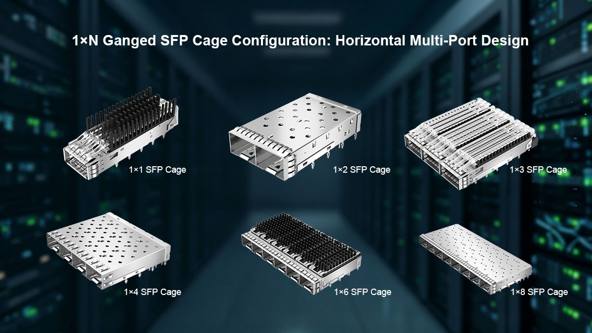
A 1×N ganged SFP cage combines multiple transceiver openings into one horizontal metal assembly. It is designed to accommodate several SFP or SFP+ modules in a single row, improving front-panel port density and maintaining consistent spacing between adjacent interfaces.
What Is a 1×N Ganged SFP Cage?
A 1×N ganged cage is a multi-port enclosure in which several SFP openings are mechanically integrated into one assembly. Unlike independent 1×1 cages, the ports share a common structural arrangement.
The notation indicates one horizontal row containing N ports.
Common examples include:
-
1×2 SFP cage: Two horizontally arranged ports.
-
1×4 SFP cage: Four horizontally arranged ports.
-
1×6 SFP cage: Six horizontally arranged ports.
-
1×8 SFP cage: Eight horizontally arranged ports.
-
1×10 SFP cage: Ten horizontally arranged ports.
The exact configurations available depend on the manufacturer's product portfolio and the specific SFP or SFP+ mechanical design.
A ganged cage may incorporate shared metal walls, structural supports, grounding contacts, and EMI shielding features. However, the internal shielding arrangement and individual port separation vary by product.
Some assemblies are supplied as cage-only components, while others include integrated electrical connectors.
Benefits and Design Trade-Offs of 1×N Ganged Cages
The primary benefit of a 1×N ganged SFP cage is more efficient horizontal port integration. By combining several openings into one assembly, it can simplify mechanical alignment and reduce the number of individual cage components.
Key advantages:
-
Consistent port spacing: Integrated construction helps maintain uniform distances between transceiver openings.
-
Higher horizontal density: Multiple interfaces can be arranged within a defined front-panel region.
-
Simplified mechanical integration: One assembly can replace several independent cage housings.
-
PCB edge utilization: Suitable for designs that have sufficient horizontal PCB space.
-
Assembly efficiency: Depending on the mounting method, multi-port assemblies can reduce individual cage placement operations.
Nevertheless, a ganged arrangement introduces some design trade-offs.
-
Horizontal space requirements increase with the number of ports.
-
The integrated assembly offers less freedom to reposition individual interfaces.
-
A large metal assembly may complicate component replacement or PCB rework.
-
Closely spaced transceivers require careful thermal and airflow evaluation.
-
The PCB footprint must match the cage's mounting-pin positions and tolerances.
For this reason, engineers should evaluate the complete cage assembly and PCB footprint rather than selecting a configuration solely by the number of openings.
Common Applications of 1×N Ganged SFP Cages
Horizontal ganged SFP cages are particularly useful in equipment that needs multiple optical interfaces arranged along a single front-panel row.
Common applications include:
-
Ethernet access and aggregation switches.
-
Enterprise network switches.
-
Data center switching equipment.
-
Network interface cards with multiple SFP ports.
-
Optical transport equipment.
-
Communication line cards.
For example, a 1×8 SFP cage can provide eight horizontally aligned optical interfaces in one assembly. This arrangement is suitable when the chassis provides sufficient horizontal width but limited vertical space.
The final design should also account for transceiver insertion clearance, module extraction access, LED visibility, and the airflow path around adjacent modules.
2×N Stacked SFP Cage Configuration: Dual-Row Port Design
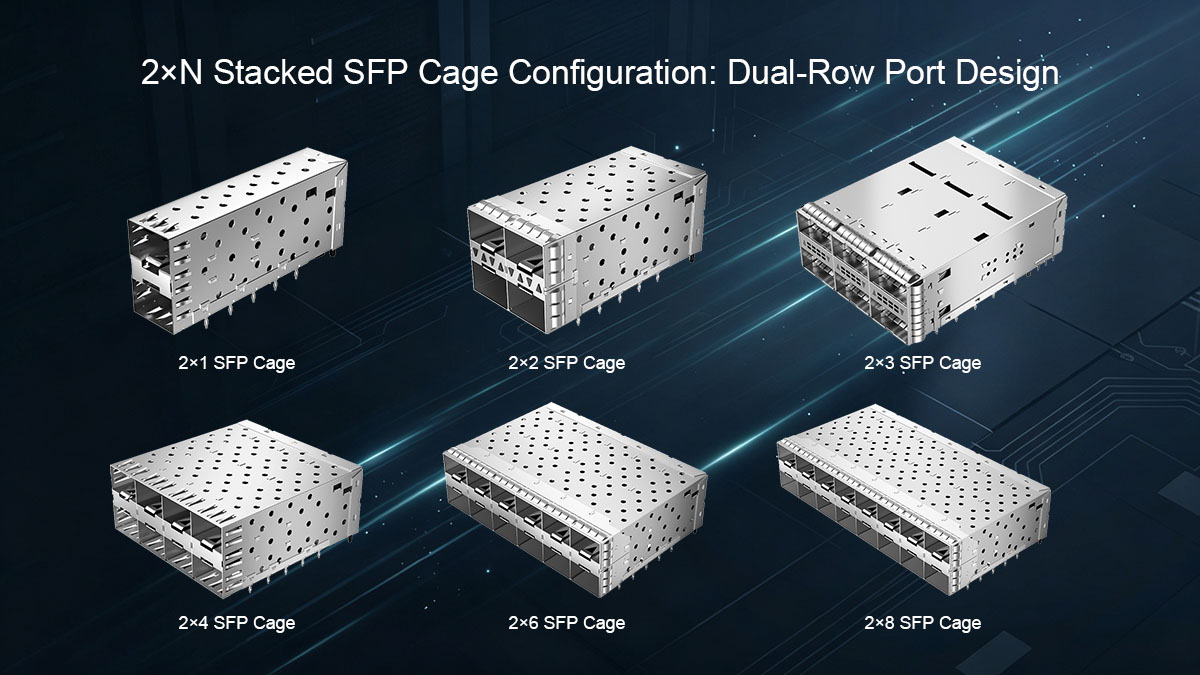
A 2×N stacked SFP cage arranges transceiver openings in two vertical rows, with N ports in each row. This configuration increases front-panel port density by using vertical space and is particularly suitable for networking equipment that requires numerous optical interfaces within a restricted chassis width.
What Is a 2×N Stacked SFP Cage?
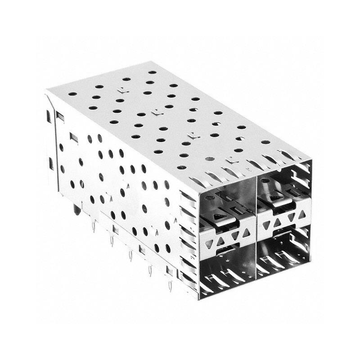
A 2×N SFP cage uses a dual-row arrangement in which two horizontal rows of transceiver ports are positioned vertically.
Representative configurations include:
-
2×1: Two vertically arranged SFP ports.
-
2×2: Four ports arranged in two rows.
-
2×4: Eight ports arranged in two rows.
-
2×6: Twelve ports arranged in two rows.
The primary difference between 1×N and 2×N designs is the vertical arrangement of the ports.
For example, a 1×8 cage accommodates eight ports in one horizontal row, while a 2×4 cage accommodates eight ports in two rows of four.
Stacked assemblies can be designed as cage-only structures or as integrated cage-and-connector assemblies. In the integrated version, the electrical receptacles and metal cage are combined into a pre-aligned component.
This integration can help reduce the mechanical alignment requirements between separately installed cage and connector components.
Advantages and Challenges of Stacked SFP Cages
The main advantage of a 2×N stacked configuration is its ability to increase port density without requiring a proportionally wider front panel.
Advantages include:
-
Higher front-panel density: Two rows accommodate more ports within a limited horizontal width.
-
Efficient chassis utilization: Vertical stacking makes better use of available front-panel height.
-
Integrated assembly options: Cage-and-connector designs can simplify mechanical alignment.
-
Consistent port arrangement: Integrated construction helps maintain uniform spacing between the two rows.
-
Suitable for high-port-count systems: Supports dense optical interfaces in switches and communication equipment.
However, stacked SFP cage assemblies also introduce additional engineering challenges.
-
More complicated PCB component placement and routing.
-
Greater restrictions on component clearance around the cage.
-
Potential airflow obstruction between adjacent transceiver rows.
-
Increased thermal interaction between neighboring modules.
-
More demanding mechanical alignment with the front-panel bezel.
-
Additional considerations for module insertion and removal access.
Thermal management deserves particular attention. When multiple high-power optical transceivers operate in a compact stacked arrangement, the heat generated by neighboring modules can increase the temperature inside the cage assembly.
Depending on the application, engineers may need to consider integrated heatsinks, chassis airflow, and the transceiver's maximum operating temperature.
Typical Applications of 2×N Stacked SFP Cages
Stacked SFP cage configurations are commonly used in high-density networking platforms where front-panel width is limited.
Typical applications include:
-
High-density Ethernet switches.
-
Data center top-of-rack switches.
-
Enterprise aggregation routers.
-
Telecommunications equipment.
-
Network appliances with multiple optical uplinks.
-
High-capacity optical communication line cards.
For example, a 2×4 stacked cage provides eight SFP interfaces within a two-row arrangement. Compared with a single horizontal row, it can reduce the required front-panel width, although the chassis must provide adequate vertical clearance.
Engineers should verify the complete mechanical envelope, including cage height, connector position, module extraction space, and front-panel opening dimensions.
Belly-to-Belly SFP Cage Configuration: Opposite-Side PCB Mounting
Belly-to-belly SFP cage mounting places two cage assemblies on opposite surfaces of the same PCB. Instead of arranging all transceiver interfaces on one side of the board, this architecture uses both PCB surfaces to increase the available port density within a compact hardware design.
What Is a Belly-to-Belly SFP Cage Design?
Belly-to-belly is a PCB mounting arrangement in which two SFP cage assemblies are installed on opposite sides of a printed circuit board.
The main structural characteristics include:
-
One cage assembly mounted on the top PCB surface.
-
Another cage assembly mounted on the bottom PCB surface.
-
Opposing cage positions designed to fit within the same PCB region.
-
Mounting-pin and connector arrangements coordinated between both sides.
-
Mechanical clearance designed to prevent interference between opposing components.
This arrangement can improve space utilization because both PCB surfaces accommodate pluggable interfaces.
However, belly-to-belly mounting does not automatically mean that the cage itself is a 2×N stacked assembly. The terms describe different aspects of the design:
-
2×N stacked: Describes the number and arrangement of port rows within a cage assembly.
-
Belly-to-belly: Describes the mounting position of two assemblies on opposite PCB surfaces.
A single-port 1×1 cage or a horizontal ganged cage may support belly-to-belly mounting if its mechanical design, compliant pins, and PCB layout are specifically compatible.
For example, Molex documentation identifies belly-to-belly applications for certain single-port and ganged cage assemblies.
Belly-to-Belly vs. 2×N Stacked SFP Cages
Although both designs can increase port density, their mechanical architectures are different. A stacked cage integrates multiple port rows into one assembly, while belly-to-belly uses two separate cage assemblies mounted on opposite PCB surfaces.
The following comparison highlights the key differences.
|
Comparison Dimension |
2×N Stacked Cage |
Belly-to-Belly Design |
|---|---|---|
|
Basic structure |
Two integrated vertical port rows |
Two cage assemblies on opposite PCB sides |
|
PCB mounting |
Usually one primary board surface |
Both PCB surfaces |
|
Port arrangement |
Vertically stacked openings |
Opposing top-side and bottom-side interfaces |
|
Assembly architecture |
Integrated multi-port cage or cage-and-connector |
Two separate assemblies |
|
PCB utilization |
Concentrates ports in one front-panel region |
Uses both PCB surfaces |
|
Mechanical design |
Requires vertical cage and bezel alignment |
Requires opposite-side clearance and alignment |
|
Thermal management |
Airflow between stacked modules |
Cooling on both PCB sides |
|
PCB layout |
Multi-row footprint and routing |
Opposing footprints and component clearance |
The choice depends on the available chassis space and the overall PCB architecture. A stacked assembly is generally more straightforward when all interfaces need to face the same side of the equipment, while belly-to-belly is worth evaluating when both board surfaces can support optical interfaces.
Key PCB and Mechanical Considerations for Belly-to-Belly Designs
Belly-to-belly integration requires careful mechanical coordination because components mounted on one PCB surface can interfere with those on the opposite side.
Before finalizing the layout, engineers should evaluate the following factors.
PCB thickness and component clearance
-
Confirm the PCB thickness specified for the selected cage.
-
Check the vertical clearance between opposing cage assemblies.
-
Ensure that mounting pins and solder joints do not interfere with opposite-side components.
-
Verify that nearby capacitors, resistors, and other components do not obstruct the cage.
Mounting-pin and connector alignment
-
Confirm the position and dimensions of press-fit or solder-tail pins.
-
Check the PCB plated-through-hole pattern.
-
Verify that the electrical receptacle aligns with the cage opening.
-
Follow the manufacturer's recommended PCB layout for belly-to-belly mounting.
EMI shielding and grounding
-
Confirm that grounding contacts maintain the intended connection to the chassis.
-
Check EMI spring-finger contact with the bezel.
-
Evaluate potential electromagnetic leakage around adjacent cage structures.
-
Ensure that the opposite-side arrangement does not compromise shielding continuity.
Thermal management and airflow
-
Evaluate heat accumulation on both PCB surfaces.
-
Consider airflow direction and available cooling paths.
-
Check whether transceiver heatsinks or other thermal features are required.
-
Verify operating temperature under the expected system load.
Belly-to-belly mounting can provide significant PCB space advantages, but only when the cage dimensions, mounting structures, and chassis geometry are designed together. The mechanical drawings for the exact component should always take precedence over generalized layout assumptions.
How to Choose the Right SFP Cage Port Configuration
Choosing the right SFP cage configuration requires balancing port density, available PCB space, mechanical compatibility, thermal performance, and assembly requirements. A configuration that works well in a compact industrial switch may not be suitable for a high-density data center switch.
The selection process should begin with the equipment's physical architecture and then move to electrical, thermal, and manufacturing requirements.
Match Port Density with Front-Panel and PCB Space
The available front-panel width and height are two of the most important factors when selecting an SFP cage configuration. Engineers should determine how many optical interfaces are required and how much physical space is available for each port.
The following guidelines provide a practical starting point:
-
Choose 1×1: When the design requires independent port positioning, flexible PCB placement, or only a small number of optical interfaces.
-
Choose 1×N ganged: When multiple SFP ports need to be arranged horizontally and the front panel provides sufficient width.
-
Choose 2×N stacked: When higher port density is required within limited horizontal space and the chassis supports two vertical rows.
-
Consider belly-to-belly: When both PCB surfaces are available for component integration and the mechanical design supports opposing cage assemblies.
Engineers should also account for the space required for transceiver insertion, extraction, LED indicators, and surrounding chassis components. The physical opening alone does not represent the complete installation envelope.
Evaluate Thermal Management and EMI Requirements
Thermal management and electromagnetic interference control are essential considerations, particularly in high-density SFP and SFP+ equipment.
Different cage configurations create different thermal and shielding conditions. Closely arranged transceivers may restrict airflow, while multi-port assemblies require consistent grounding and shielding across the complete structure.
Important evaluation points include:
Thermal management
-
Determine the power consumption and operating temperature of the intended transceivers.
-
Evaluate airflow around adjacent SFP modules.
-
Check whether the cage supports an integrated heatsink.
-
Confirm that the heatsink has sufficient clearance from the chassis.
-
Consider thermal interaction between neighboring ports.
EMI shielding
-
Check the availability and arrangement of EMI spring fingers.
-
Evaluate grounding contact between the cage and front-panel bezel.
-
Determine whether an elastomeric gasket or additional shielding structure is required.
-
Verify that the cage provides suitable shielding for the equipment's electromagnetic compatibility requirements.
A metal cage provides a mechanical enclosure and contributes to EMI containment, but its actual shielding performance depends on the complete system design, including grounding, bezel contact, PCB layout, and chassis construction.
Verify PCB Mounting Methods and Mechanical Compatibility
PCB compatibility should be verified against the exact SFP cage part number before the board layout is released. Even cages with identical port configurations can have different dimensions, mounting-pin arrangements, and termination methods.
The following specifications should be checked:
-
Mounting method: Through-hole press-fit or through-hole solder.
-
PCB thickness: Confirm the supported board thickness.
-
Pin dimensions: Check compliant-pin or solder-tail dimensions.
-
PCB footprint: Verify mounting-hole locations and plated-through-hole requirements.
-
Cage dimensions: Check overall height, width, and length.
-
Connector alignment: Confirm the electrical receptacle position relative to the cage.
-
Front-panel compatibility: Verify bezel openings and transceiver insertion clearance.
-
Additional features: Check light pipes, heatsinks, grounding pins, and EMI spring structures.
For press-fit designs, the PCB hole diameter, plating, board thickness, and insertion tooling must comply with the manufacturer's specifications. For solder-mounted cages, engineers should verify solder-tail geometry and compatibility with the intended assembly process.
It is also important to distinguish a standalone cage from an integrated cage-and-connector assembly. The former requires a separately mounted electrical receptacle, while the latter combines both mechanical and electrical components.
Compare SFP Cage Configurations for Different Applications
The four main configurations serve different hardware requirements. Comparing their structural characteristics helps engineers narrow down the appropriate design before reviewing individual product drawings.
|
Configuration |
Port Arrangement |
Main Advantage |
Primary Consideration |
Typical Application |
|---|---|---|---|---|
|
1×1 |
One independent port |
Flexible positioning |
Lower port density |
Industrial switches, media converters |
|
1×N Ganged |
One horizontal row |
Efficient horizontal integration |
Requires sufficient front-panel width |
Access and aggregation switches |
|
2×N Stacked |
Two integrated vertical rows |
High front-panel density |
Vertical clearance and thermal management |
High-density switches |
|
Belly-to-Belly |
Assemblies on opposite PCB surfaces |
Uses both PCB surfaces |
Opposite-side clearance and cooling |
Compact network hardware |
For example, a design requiring four optical interfaces may use four independent 1×1 cages, one 1×4 ganged cage, or another arrangement depending on the available PCB and chassis space.
The best configuration is therefore not necessarily the one with the highest port count. It is the one that satisfies the complete mechanical, electrical, and thermal requirements of the host equipment.
LINK-PP SFP Cage Solutions for Different Port Configurations
At LINK-PP, our SFP Cage portfolio covers multiple port arrangements and mechanical designs for optical networking equipment. These options include single-port cages, horizontal ganged assemblies, and stacked configurations, with different mounting methods and optional structural features.
Rather than treating all SFP cages as interchangeable, we organize our product selection around port configuration, termination method, EMI shielding, and additional integration requirements. This makes it easier for hardware engineers to identify a suitable starting point for their PCB and chassis designs.

LINK-PP SFP Cage Portfolio: From Single-Port to High-Density Designs
Our SFP and SFP+ cage product range includes several common port matrix configurations.
Single-port configurations
-
1×1 SFP Cage.
-
1×1 SFP+ Cage.
These are suitable for equipment requiring individual optical interfaces and flexible component placement.
Horizontal ganged configurations
-
1×2 SFP Cage.
-
1×4 SFP Cage.
-
1×6 SFP Cage.
-
1×8 SFP Cage.
-
1×10 SFP Cage.
These configurations support multiple horizontally aligned ports in a common assembly.
Stacked configurations
-
2×1 SFP Cage.
-
2×2 SFP Cage.
-
2×4 SFP Cage.
-
2×6 SFP Cage.
-
2×8 SFP Cage.
These options provide two-row port arrangements for applications requiring higher front-panel density.
The actual configuration availability varies by product family and model. Our product catalog also distinguishes between SFP, SFP+, and other pluggable interface families, so engineers should confirm the supported form factor rather than relying on port matrix notation alone.
Key Structural Features of LINK-PP SFP Cages
Different hardware applications require different cage structures. Our product options include several features that address mechanical integration, shielding, mounting, and thermal requirements.
Metal cage construction
SFP cage housings use conductive metal structures to provide mechanical protection and contribute to EMI shielding. Material and surface treatment should be checked against the specific model's datasheet.
For example, the LINK-PP LP11AC02000 is a 1×1 SFP cage featuring EMI spring fingers and through-hole press-fit mounting. Its documented operating temperature range is -55°C to +85°C.
Press-fit and solder mounting options
Different PCB manufacturing processes may require different termination methods.
-
Press-fit mounting uses compliant pins inserted into plated-through holes.
-
Solder mounting uses solder tails to establish mechanical and electrical connections where applicable.
-
The correct choice depends on PCB specifications, assembly equipment, and the exact cage design.
EMI spring fingers and grounding structures
EMI spring fingers help establish conductive contact between the cage and the equipment bezel. Their arrangement and dimensions should be verified against the chassis design.
Optional light pipes
Some cage models incorporate light pipes to direct status LED indicators toward the front panel. This is useful when port-level link and activity indicators need to remain visible after the equipment is assembled.
Optional heatsinks
Selected cage assemblies include heatsink structures to support thermal management. Engineers should verify the heatsink dimensions, transceiver clearance, and compatibility with the system airflow.
These features are model-dependent. Not every cage includes a light pipe, heatsink, or integrated electrical connector, so checking the individual product specification is essential.
How to Select a LINK-PP SFP Cage for Your Hardware Design
Selecting an appropriate model involves more than matching a 1×N or 2×N port configuration. The cage must also fit the PCB footprint, electrical connector, front-panel opening, and thermal design.
We recommend following this evaluation process:
-
Identify the port configuration: Determine whether the application requires 1×1, 1×N ganged, or 2×N stacked construction.
-
Confirm the interface form factor: Check whether the equipment uses SFP, SFP+, or another compatible interface family.
-
Determine the mounting method: Identify whether press-fit or solder termination is required.
-
Check mechanical dimensions: Compare cage height, width, length, mounting-pin positions, and PCB thickness.
-
Evaluate EMI requirements: Confirm the required spring fingers, grounding features, and bezel contact arrangement.
-
Review thermal features: Determine whether an integrated heatsink or additional cooling provision is necessary.
-
Verify the product drawing: Compare the manufacturer's mechanical drawing and PCB footprint with the host board design.
For example, the LINK-PP LP21AC01001 is a 2×1 stacked SFP cage-and-receptacle assembly. It integrates the electrical connector and mechanical cage into one pre-aligned structure, making it a different component category from a standalone cage.
By checking these details before finalizing the PCB, engineers can reduce the risk of mechanical interference, connector misalignment, and unnecessary layout revisions.
Why Consider LINK-PP for SFP Cage Requirements?
SFP cage selection often involves several related component requirements rather than one isolated specification. Port arrangement, PCB termination, shielding, and optional accessories all influence the final design.
Our product range provides options covering different hardware architectures, including:
-
Multiple SFP and SFP+ port matrix configurations.
-
Single-port, horizontal ganged, and stacked cage structures.
-
Press-fit and solder mounting options across applicable models.
-
EMI spring-finger shielding designs.
-
Models with optional light pipes and heatsinks.
-
Standalone cage components and selected integrated cage-and-connector assemblies.
We also provide product specifications and mechanical drawings to support engineering evaluation. These documents are particularly important when comparing different cage models that share the same port configuration but have different PCB footprints or mounting requirements.
If a standard configuration does not fully match your hardware requirements, our team can help review the relevant dimensions and technical specifications to identify an appropriate product option.
Conclusion
Selecting the right SFP cage port configuration is essential for achieving the desired port density, PCB utilization, mechanical compatibility, and thermal performance. Whether a design uses 1×1 single-port cages, 1×N ganged assemblies, 2×N stacked structures, or belly-to-belly mounting, each configuration addresses different hardware integration requirements.
The key differences can be summarized as follows:
-
1×1 SFP Cage: Provides independent port positioning and flexible PCB integration.
-
1×N Ganged SFP Cage: Combines multiple horizontally arranged ports into one assembly.
-
2×N Stacked SFP Cage: Uses two vertical port rows to increase front-panel density.
-
Belly-to-Belly SFP Cage: Utilizes both PCB surfaces to accommodate opposing cage assemblies.
Beyond port arrangement, engineers should verify PCB footprints, mounting methods, EMI shielding, connector alignment, and thermal requirements before finalizing a design.
At LINK-PP, we offer a range of SFP and SFP+ cage configurations for different networking hardware applications. Visit the LINK-PP Official Store to explore available models, review technical specifications, and request a quotation for your project. Standard-stock items are covered by a 15-day no-reason return and exchange policy, and covers return shipping costs for quality-related issues. Our team is also available to help identify suitable cage configurations based on your PCB layout and mechanical requirements.