



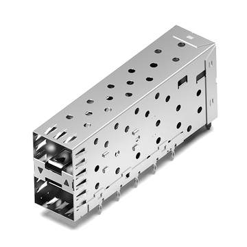



Choosing the right SFP cage requires more than checking its overall length, width, and height. You also need to verify internal clearance, mechanical tolerances, and the dimensional requirements of the optical module and host equipment. These details help prevent installation problems and ensure that the cage fits the intended hardware design.
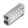
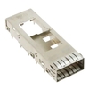
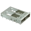
An SFP cage is a metal enclosure that holds an SFP transceiver and provides mechanical support, shielding, and a defined interface with the host equipment. Its dimensions affect how the module fits inside the enclosure, how the assembly connects to the PCB, and how the port aligns with the equipment's front panel.
A small dimensional mismatch can cause problems such as difficult module insertion, poor alignment, or interference with nearby components. Understanding the mechanical drawing is therefore an important first step before selecting or replacing a component.
Understanding Standard SFP Cage Dimensions
Standard SFP cage specifications define the basic mechanical dimensions and structural requirements of the cage assembly. These measurements provide a reference for hardware designers to evaluate the enclosure size, internal space, and mounting arrangement.
The original SFP Multi-Source Agreement (MSA), INF-8074i, includes reference drawings for SFP cage assemblies. These specifications establish important mechanical design requirements, but the actual dimensions of a selected product should always be checked against its manufacturer's drawing.
Overall Length, Width, and Height
The overall dimensions describe the external space occupied by the metal enclosure. They are usually the first measurements to check because they determine whether the component can fit within the available space in the host equipment.
For reference, the original SFP MSA (INF-8074i) specifies the following maximum dimensions for its cage assembly:
| Dimension | Reference Value | Description |
| Overall Length | 48.8mm Max. | Maximum length of the cage assembly |
| Overall Width | 15.0mm Max. | Maximum width of the cage assembly |
| Assembly Height | 9.8mm Max. | Maximum height from the host board |
These values describe the reference SFP cage assembly in the original MSA drawing. Actual product dimensions may vary depending on the cage structure and mounting design.
When reviewing these measurements, consider three directions:
- Length: Check the available space behind the front panel and around other PCB components.
- Width: Check the distance between adjacent ports and nearby components.
- Height: Check the vertical space between the PCB and the chassis or other internal structures.
Checking all three dimensions helps identify potential mechanical conflicts before assembly.
Internal Dimensions and Module Clearance
External measurements show how much space the enclosure occupies, while internal dimensions describe the space available for the transceiver.
The original SFP MSA reference drawing provides two useful internal measurements:
| Internal Measurement | Reference Value | Description |
| Inside Width | 14.0 ± 0.1mm | Internal horizontal space |
| Inside Height | 8.95 ± 0.15mm | Internal vertical space |
These measurements help designers understand the available space inside the enclosure. They should be considered alongside the module's housing profile and mechanical features.
For example, the internal width determines the horizontal space available for the transceiver, while the internal height affects the vertical fit between the module and cage structure.
Standard SFP Mechanical Specifications
The original SFP MSA, INF-8074i, defines the mechanical requirements for SFP modules and their corresponding cage assemblies.
The specification provides reference dimensions and structural requirements that help designers develop compatible optical interfaces.
When selecting an SFP cage, consider the following:
- Identify the mechanical requirements of the SFP module.
- Refer to the corresponding MSA mechanical drawings.
- Compare the module and cage dimensions.
- Confirm the required mechanical and EMI compatibility.
Although the MSA provides a common reference, individual cage products may have different mounting structures, shielding features, and external dimensions.
Dimensional Tolerances in SFP Cage Drawings
Mechanical drawings include dimensional tolerances that define how much a measurement can vary while remaining within the design requirements.
Common dimensional notations include:
| Drawing Notation | Example | Meaning |
| Maximum | 48.8mm Max. | The measurement must not exceed 48.8mm |
| Minimum | Minimum value specified in drawing | The measurement must not fall below the stated limit |
| ± Tolerance | 14.0 ± 0.1mm | Acceptable range is 13.9 - 14.1mm |
| Basic Dimension | 14.25mm Basic | A theoretically exact reference dimension |
These tolerances matter because even small variations can affect how two mechanical parts fit together.
When reviewing a product drawing, pay attention to:
- Critical Dimensions: Identify measurements that directly affect module fit and installation.
- Tolerance Ranges: Check the permitted variation rather than relying only on nominal values.
- Reference Dimensions: Understand which measurements define actual limits and which provide supporting design information.
Two cages should not be considered interchangeable simply because their nominal dimensions look similar. Their tolerance ranges and mechanical details must also be compatible.
SFP Cage Dimensions and Optical Module Compatibility
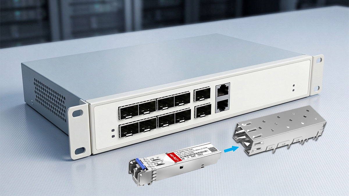
An SFP cage must match the mechanical design of the optical transceiver installed inside it. Differences in housing dimensions, latch structures, or insertion requirements may affect how the module fits, even when two transceivers share the same form factor.
The enclosure and transceiver work together as part of the host interface. The cage provides mechanical guidance and retention, while the host connector establishes the electrical connection.
Matching Cage Dimensions to SFP Module Sizes
The first step in compatibility checking is to identify the module form factor and compare its mechanical dimensions with the cage specifications.
When comparing a module with its enclosure, focus on these areas:
- Module Width: Check whether the transceiver housing fits within the available internal width.
- Module Height: Confirm that the housing has sufficient vertical clearance.
- Module Length: Check the insertion depth and the position of the rear electrical interface.
- Housing Profile: Compare the module's shape and mechanical features with the cage structure.
Special module designs may have different housing or thermal structures that require a specifically designed cage.
Matching the form factor is only the starting point. Always compare the actual mechanical drawings before confirming compatibility.
Checking Internal Clearance and Module Insertion Space
Internal clearance determines whether a transceiver can move into the correct position without contacting the surrounding metal structure.
Three areas deserve particular attention:
- Side Clearance: The space between the module housing and cage walls must meet the specified mechanical requirements.
- Vertical Clearance: The distance between the module's upper and lower surfaces and the corresponding cage structures must allow the transceiver to fit correctly.
- Insertion Depth: The module must travel far enough into the enclosure to reach the host connector and establish the intended electrical connection.
A suitable fit allows the transceiver to enter smoothly and reach its designated position without unnecessary mechanical interference.
Understanding Latch and Retention Mechanism Clearance
The latch mechanism keeps an optical transceiver securely installed inside the cage. It also allows technicians to release and remove the module during maintenance.
When checking this area, consider the following:
- Latch Position: Confirm that the module's locking feature aligns with the cage's retention structure.
- Engagement Space: Ensure that the latch can engage when the module reaches its installed position.
- Release Clearance: Allow enough room for the release mechanism to operate during removal.
- Retention Structure: Verify that the cage can hold the module securely under normal handling conditions.
If the latch cannot engage fully, the module may not remain securely installed. If the release mechanism is blocked, technicians may have difficulty removing it.
Verifying Cage and Host Connector Alignment
The cage must also align correctly with the host connector mounted on the PCB. The enclosure guides the module into position, while the connector provides the electrical interface.
Three alignment points are important:
| Alignment Area | What to Verify |
| Horizontal Position | Cage and connector centerlines |
| Vertical Position | Connector height relative to the cage |
| Insertion Position | Connector location and module insertion depth |
The PCB layout and mechanical drawing should be reviewed together to confirm that the connector is positioned correctly inside the enclosure.
For new hardware designs, 3D CAD models can help identify potential interference before PCB fabrication. This is particularly useful when several components are installed close to the optical interface.
SFP Cage Dimensions for PCB Footprint and Mounting
SFP cage dimensions must match the PCB layout and mounting requirements of the host equipment. Besides checking the enclosure's external size, designers need to verify the footprint, mounting hole positions, solder pin layout, and board thickness.
Different cage designs use different mounting methods, including through-hole solder and press-fit structures. Their PCB layouts and installation requirements are not necessarily interchangeable.
PCB Footprint and Mounting Hole Layout
A PCB footprint defines the copper pads, drilled holes, and placement areas required to mount a component on a printed circuit board.
For an SFP cage, the footprint must match the actual mounting features shown in the manufacturer's mechanical drawing.
When checking the PCB layout, pay attention to:
- Pad Layout: Confirm that the PCB pads match the positions and dimensions of the mounting pins.
- Mounting Hole Positions: Check the location, diameter, and spacing of the required holes.
- PCB Edge Position: Verify the cage's position relative to the board edge.
- Keep-Out Area: Reserve sufficient space around the enclosure for installation and nearby components.
A footprint mismatch may prevent the mounting pins from fitting into the PCB holes or cause the cage to sit in an incorrect position.
Always use the footprint recommended by the manufacturer instead of estimating the layout from external dimensions.
Solder Post and Press-Fit Pin Spacing
SFP cages use different mounting methods depending on their construction and application requirements.
| Mounting Type | Main Characteristics | Key Dimensions to Check |
| Through-Hole Solder | Metal posts pass through PCB holes and are soldered in place | Pin diameter, hole diameter, and pin spacing |
| Press-Fit | Compliant pins are inserted into plated PCB holes | Pin geometry, finished hole size, and spacing |
Through-Hole Solder Mounting
The solder posts must align with the corresponding PCB holes. Their position and dimensions affect insertion, soldering, and the final mounting position.
Press-Fit Mounting
Press-fit pins rely on a specified relationship between the pin geometry and plated hole dimensions. The PCB hole size and plating requirements must follow the manufacturer's application specifications.
Do not assume that a solder-mounted cage can directly replace a press-fit version, even if both have similar external dimensions.
Recommended PCB Thickness and Mounting Requirements
PCB thickness is another important factor when selecting a cage. The board must provide the correct mechanical support for the mounting structure.
Some SFP cage product drawings specify a recommended PCB thickness of 1.5mm or 1.57mm. However, these values are not universal and should not be applied to every cage design.
Before selecting a component, check:
- Board Thickness: Confirm that the PCB thickness matches the product specification.
- Hole Diameter: Verify the finished hole dimensions for solder or press-fit mounting.
- Copper Plating: Check the required plated-through-hole specifications where applicable.
- Mounting Support: Ensure that the board can support the enclosure without unwanted movement.
- Installation Process: Follow the manufacturer's recommended soldering or press-fit procedure.
A mismatch between board thickness and mounting requirements can affect the final cage position and mechanical stability.
Component Clearance and PCB Keep-Out Areas
The space occupied by an SFP cage extends beyond its mounting footprint. Its metal housing and mounting pins may affect the placement of nearby electronic components.
A keep-out area is a reserved region on the PCB where other components or copper features should not be placed unless the design specifically permits them.
When planning the surrounding layout, consider:
- Adjacent Components: Avoid physical interference between the cage and nearby components.
- Mounting Pin Clearance: Reserve the required space around solder tails or press-fit pins.
- Connector Access: Make sure the cage does not interfere with the host connector.
- Assembly Space: Allow sufficient room for manufacturing tools and installation operations.
For high-density PCB designs, these clearances become especially important because multiple cages may be installed close together.
Comparing SFP Cage Dimensions Across Port Configurations
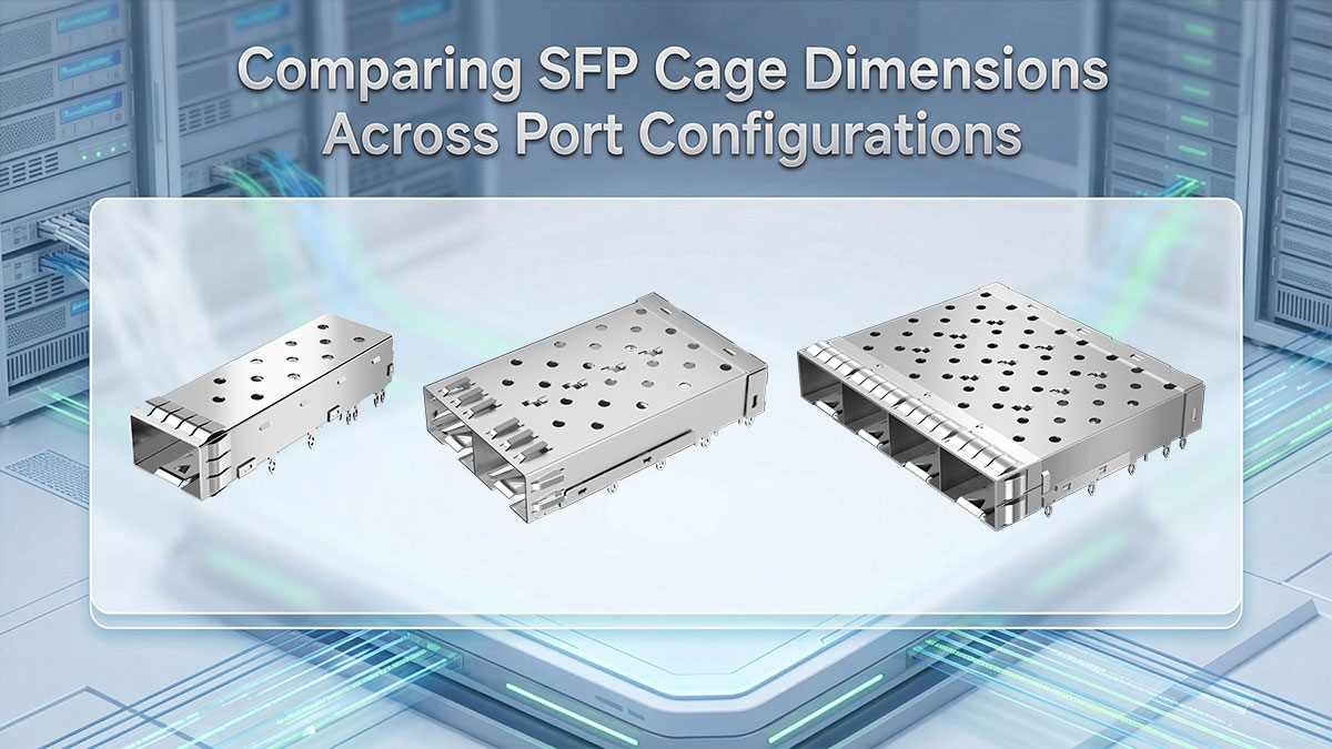
SFP cages are available in different port configurations, including 1×1, 1×2, 1×4, and 1×6 designs. As the number of ports increases, the overall cage width, port spacing, and PCB mounting layout may also change.
Single-port cages provide individual optical interfaces, while ganged cages combine multiple ports into one assembly. The selected configuration should match the required port count and available installation space.
Single-Port SFP Cage Dimensions (1×1)
A 1×1 SFP cage provides one opening for a single optical transceiver. Its compact structure is suitable for equipment that requires individual SFP ports.
When checking a single-port design, focus on:
- Overall Width: Check the horizontal space occupied by the enclosure.
- Overall Height: Confirm that the cage fits within the available vertical space.
- Mounting Footprint: Verify the position of the mounting pins and PCB holes.
- Internal Clearance: Ensure that the enclosure accommodates the intended transceiver.
A single-port structure offers flexibility when designing equipment with different port locations. However, the distance between individual cages must still be considered when several units are installed on the same PCB.
Dual-Port SFP Cage Dimensions (1×2)
A 1×2 SFP cage accommodates two transceivers in one assembly. The two openings are typically arranged side by side within a shared enclosure structure.
Compared with a single-port design, a dual-port cage requires additional horizontal space.
The main dimensions to check include:
- Total Width: Measure the complete enclosure rather than estimating it from one port.
- Port Center Spacing: Check the distance between the centers of the two openings.
- Mounting Pin Layout: Confirm that the PCB footprint matches the dual-port structure.
- Port Arrangement: Check that both openings follow the intended layout.
A dual-port assembly can simplify the mechanical arrangement of two adjacent interfaces, but its mounting pattern may differ from that of two separate single-port cages.
Multi-Port SFP Cage Dimensions (1×4 and 1×6)
Multi-port cages accommodate four or six transceivers in a shared assembly. They are commonly used in network switches, routers, and other equipment requiring a higher density of optical interfaces.
| Feature | 1×4 Cage | 1×6 Cage |
| Port Count | 4 | 6 |
| Overall Width | Product-specific | Product-specific |
| Port Spacing | Defined by drawing | Defined by drawing |
| PCB Footprint | Four-port assembly | Six-port assembly |
| Installation Space | Room for four modules | Additional space for six modules |
As more ports are added, the overall width and PCB mounting layout become increasingly important.
A higher port count does not automatically mean that every design has a proportionally larger width. Shared walls, side structures, and different port spacing arrangements can affect the final dimensions.
Always compare the complete mechanical drawings when choosing between multi-port configurations.
Port Pitch and Overall Width in Ganged Cages
Port pitch refers to the center-to-center distance between adjacent ports. It is an important measurement because it determines how closely the transceiver openings are arranged.
For example, if a cage has a port pitch of 21.2mm, the center of one port is 21.2mm away from the center of the adjacent port.
When reviewing port pitch and overall width, check:
- Center-to-Center Distance: Confirm the spacing between adjacent port openings.
- Sidewall Dimensions: Account for the metal structure surrounding the outermost ports.
- Shared Wall Design: Check how the internal walls affect neighboring module positions.
- Total Assembly Width: Use the manufacturer's drawing to confirm the complete external width.
Port pitch and the distance between the outer edges of two openings are different measurements and should not be used interchangeably.
Consistent spacing also helps align the cage openings with the chassis panel in multi-port equipment.
SFP Cage Dimensions for Chassis and Panel Integration
SFP cage dimensions must match the chassis opening and front-panel mounting requirements to ensure proper equipment assembly. Even if the enclosure fits the PCB and accepts the optical transceiver, an incorrect panel opening or mounting position can prevent proper installation.
The cage, PCB, and front panel work together as one mechanical assembly. Their relative positions determine whether the optical port is properly exposed and whether the shielding structure makes the intended contact with the chassis.
Front Panel Cutout and Opening Dimensions
A front panel cutout is the opening in the equipment's chassis through which the optical transceiver can be accessed. Its dimensions must correspond to the position and size of the cage opening.
When checking the panel opening, consider:
- Opening Width: Ensure that the cutout provides enough horizontal space for the port.
- Opening Height: Check that the vertical opening matches the cage's front profile.
- Opening Position: Confirm that the cutout aligns with the port centerline.
- Panel Edge Clearance: Allow sufficient space around the opening for the cage structure.
A cutout that is too small may interfere with the cage or module during installation. An opening that is too large may leave unwanted gaps around the port and affect the intended shielding arrangement.
Cage Mounting Height and Panel Alignment
Mounting height describes the vertical position of the cage relative to the PCB. It affects how the enclosure lines up with the front panel.
Several factors influence this alignment:
- PCB Position: Check the board's installed height and its distance from the chassis reference surface.
- Cage Height: Verify the enclosure's height and mounting position above the PCB.
- Panel Position: Confirm the distance between the PCB and the front-panel opening.
- Port Centerline: Ensure that the cage opening and panel cutout share the correct horizontal and vertical positions.
For example, if the PCB is mounted lower than expected, the cage opening may not align with the front-panel cutout. This can make module installation difficult or cause the metal enclosure to contact the panel incorrectly.
Using a common mechanical reference point when reviewing the PCB, cage, and chassis drawings helps prevent these alignment problems.
EMI Spring Finger Contact and Compression Space
Many SFP cages include EMI spring fingers or other shielding features to establish electrical contact with the equipment's metal front panel. These structures help maintain electromagnetic shielding around the optical port.
The spring fingers are designed to make contact with the panel when the equipment is assembled. Their position and compression range must match the mechanical design of the chassis.
When checking this area, pay attention to:
- Spring Finger Position: Confirm that the contact features align with the intended panel surface.
- Compression Range: Follow the manufacturer's specified deflection limits.
- Panel Thickness: Check that the front panel falls within the supported mechanical range.
- Contact Area: Ensure that the spring fingers have sufficient contact with the conductive surface.
Insufficient compression may result in poor electrical contact, while excessive compression can deform the spring structure or make assembly difficult.
Module Insertion and Removal Clearance
A correctly installed cage should allow technicians to insert and remove optical transceivers without interference from the chassis or nearby structures.
There are several areas to check:
- Front Access Space: Provide enough room for technicians to grip and handle the module.
- Latch Operation: Ensure that the release mechanism can move freely during removal.
- Panel Edge Clearance: Prevent the module from contacting the edges of the chassis opening.
- Adjacent Port Access: Allow enough room to operate neighboring modules independently.
These requirements are especially important in high-density switches and network equipment, where multiple optical ports are arranged close together.
For example, a cage may fit the PCB and chassis opening correctly, but a nearby panel structure could still block access to the module latch. This would make routine replacement and maintenance more difficult.
SFP Cage Dimensions for Thermal and Space Management

Thermal design is an important part of SFP cage selection because the enclosure's top structure, overall height, and surrounding clearance can affect heat dissipation and airflow. Cages with integrated heatsinks and multi-port assemblies have different space requirements, so the selected structure must match the optical module's thermal needs and the available space inside the equipment.
An optical transceiver generates heat during operation. Although the cage does not determine the entire thermal performance of the system, its structure can provide an additional heat transfer path or affect airflow around the module. When reviewing a design, consider the heatsink structure, clearance above the cage, and space available around multiple ports.
Additional Space Requirements for SFP Cages with Heatsinks
An SFP cage with an integrated heatsink has an additional thermal structure above the main enclosure. This structure provides another path for transferring heat away from the transceiver, but it also increases the overall height and requires sufficient space inside the chassis.
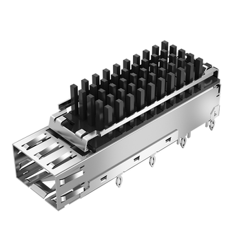
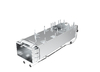
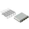
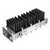
For applications that require an additional thermal structure, LINK-PP offers the LP11AC02080, an SFP 1×1 cage assembly with an integrated heatsink. Its design combines a copper-alloy cage, nickel plating, EMI spring fingers, and a through-hole press-fit mounting structure. These features provide mechanical support and an additional heat transfer path.
According to its product specifications, the cage measures 48.75mm in length, 15.10mm in width, and 18.10mm in height. It also specifies a recommended PCB thickness of 1.57mm and a tail length of 2.90mm. The operating temperature range is -55 to +85°C.
When considering this type of enclosure, check three additional requirements:
- Heatsink Height: Check the listed assembly height against the available vertical space.
- Chassis Clearance: Confirm that the heatsink does not interfere with the equipment cover or nearby components.
- Airflow Access: Keep the heatsink area sufficiently exposed to the intended cooling airflow.
The LP11AC02080 provides a practical example of a single-port SFP cage with an integrated heatsink. Its actual cooling benefit depends on the module, thermal contact, airflow, and overall system design.
Airflow Clearance Around High-Density Cage Configurations
High-density cage arrangements require careful space planning because several optical transceivers operate close together. Heat from neighboring modules may accumulate when the available airflow is restricted by the cage structure, chassis walls, or nearby components.
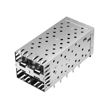
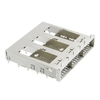
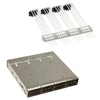
When a design requires multiple SFP ports in a compact arrangement, a multi-port cage can simplify the mechanical layout. For example, LINK-PP LP22AC01003 is a 2×2 SFP cage and connector assembly that combines four optical interfaces in one structure. It features through-hole press-fit mounting and internal and external EMI springs to support PCB installation and electromagnetic shielding.
According to its product specifications, the assembly measures 63.25mm in length, 28.75mm in width, and 25.20mm in height. It supports a four-port configuration and operates within a temperature range of -40 to +85°C.
When using this type of multi-port assembly, pay attention to:
- Port Arrangement: Check whether the 2×2 configuration matches the equipment's port layout.
- PCB Footprint: Compare the mounting-hole positions and press-fit pin layout with the manufacturer's mechanical drawing.
- Air Inlet and Outlet: Avoid blocking the intended cooling path around the optical modules.
- Vertical Clearance: Check the available space above the assembly and installed modules.
The LP22AC01003 provides a practical example of a compact four-port SFP arrangement. Its thermal suitability should be evaluated through the complete equipment layout, including module spacing, chassis ventilation, and cooling airflow.
Checking Thermal and Mechanical Design Constraints
Before finalizing a cage selection, designers should evaluate thermal requirements and mechanical installation conditions together. A cage may have a suitable thermal structure but still be unsuitable if its mounting method, overall height, or port arrangement does not match the host equipment.
The following checklist can help:
| Checkpoint | What to Confirm |
| Cage Structure | Is the design suitable for the intended thermal arrangement? |
| Overall Height | Does the complete assembly fit inside the chassis? |
| Heatsink Clearance | Is there enough space above the heatsink? |
| Airflow Path | Can cooling air reach the optical modules? |
| Mounting Method | Does the solder or press-fit structure match the PCB? |
| Port Configuration | Does the cage arrangement match the required port density? |
| EMI Design | Are the spring fingers compatible with the chassis structure? |
The two LINK-PP SFP cages illustrate different design considerations. The LP11AC02080 is suitable for applications requiring an additional heatsink structure, while the LP22AC01003 provides a four-port SFP arrangement for compact interface layouts. Neither should be selected based on dimensions alone; the module requirements, PCB design, airflow conditions, and chassis clearance must also be considered.
SFP Cage Dimensions: Final Selection Checklist
Choosing the right SFP cage involves checking its dimensions, mechanical structure, and compatibility with the host equipment. Before confirming a design, review the following points to avoid fit and installation problems.
- Overall Dimensions: Confirm that the cage length, width, and height fit within the available equipment space.
- Module Compatibility: Check that the internal dimensions and retention structure match the intended SFP transceiver.
- PCB Footprint: Verify that the mounting holes, pin layout, and board thickness meet the manufacturer's requirements.
- Port Configuration: Select a suitable 1×1, 1×2, or multi-port arrangement based on the required interface layout.
- Panel Integration: Make sure the cage opening aligns with the chassis cutout and provides sufficient access for module installation and removal.
- EMI Requirements: Ensure that the spring fingers align with the chassis contact surfaces and provide proper shielding.
- Thermal Clearance: Ensure sufficient space above heatsinks and around the cage for proper airflow.
A manufacturer's mechanical drawing should be the final reference when verifying these requirements. If standard product dimensions do not match your PCB or chassis design, discuss alternative or customized cage solutions with the supplier.
LINK-PP offers a range of SFP cages with different port configurations, mounting structures, and thermal designs. Visit the LINK-PP Official Store to explore available products, compare mechanical specifications, and find a suitable solution for your equipment.