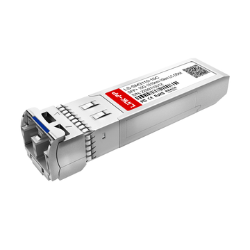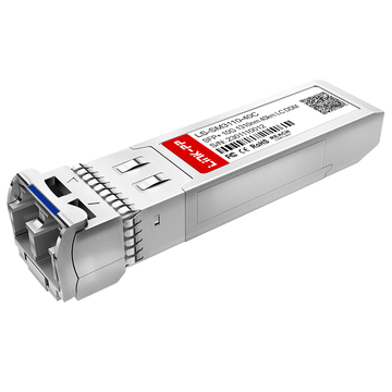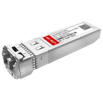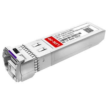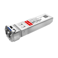
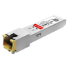
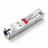
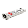


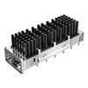





When deploying a LINK-PP 10G SFP+ module in an Avaya VSP 7200 switch, network administrators may encounter an “Unsupported Transceiver” message that complicates installation and troubleshooting. This warning can indicate a transceiver qualification restriction, an identification issue, or a platform-specific compatibility limitation. However, it does not automatically mean that the optical module is defective or that the connection cannot operate. Understanding the switch's reported status is essential before taking corrective action.
Troubleshooting the Avaya VSP 7200 Unsupported Transceiver error requires more than checking whether the module fits the SFP+ port. Hardware model, VOSS software version, module identification data, optical specifications, and link-partner compatibility can all influence the diagnosis. Distinguishing an unsupported-module warning from a detection failure or an optical link problem helps prevent unnecessary component replacements and unsupported configuration changes.
This guide explains how to investigate the error systematically, from initial identification to post-fix verification. It covers the following key areas:
-
Identifying common causes of transceiver recognition errors.
-
Using VSP 7200 CLI commands and system logs to collect diagnostic information.
-
Verifying module specifications, hardware restrictions, and software compatibility.
-
Troubleshooting module detection, port status, and optical link failures.
-
Confirming link stability and documenting the final results.
By following these checks, network administrators can narrow down the underlying cause, determine the appropriate corrective action, and make more informed decisions about 10G SFP+ deployment on Avaya VSP 7200 switches.
What Does the “Unsupported Transceiver” Error Mean on Avaya VSP 7200?
The “Unsupported Transceiver” error on an Avaya VSP 7200 indicates that the switch has identified a transceiver as unsupported under its applicable hardware or software compatibility rules. When a 10G SFP+ module triggers this message, the first step is to determine whether the switch can identify the module and whether the port can establish a link. An unsupported status does not, by itself, prove that the module is defective or that the connection must fail.
Unsupported Transceiver vs. Transceiver Not Detected
An unsupported transceiver is generally recognized by the switch but is not classified as a supported module. A transceiver that is not detected presents a different problem because the switch may be unable to retrieve its identification information or initialize the interface correctly.
The distinction helps narrow down the next diagnostic step:
-
Unsupported transceiver: The switch may report the vendor name, vendor OUI, part number, or serial number while classifying the module as unsupported.
-
Transceiver not detected: Module information may be absent, incomplete, or unavailable, which can indicate a seating problem, a physical fault, or an identification issue.
-
Transceiver recognized but link down: The module may be readable, but the interface may fail to establish a connection because of an optical mismatch, port restriction, fiber issue, or remote-end configuration.
Use the VOSS command show pluggable-optical-modules basic to inspect the available module information. The detailed command show pluggable-optical-modules detail can provide additional diagnostic fields where supported.
These observations are starting points rather than definitive diagnoses. For example, a populated vendor field does not establish full compatibility, while missing information does not automatically mean the module itself has failed. Compare the output with the exact module part number and the documentation for the installed VSP 7200 model.
How VSP 7200 Transceiver Recognition Works
The Avaya VSP 7200 uses transceiver identification information and platform-specific compatibility rules to determine how an installed optical module is handled. The result depends on the hardware variant, transceiver type, and software release; a standard SFP+ form factor alone does not guarantee that every 10Gbps module will be accepted.
During initial diagnosis, check the following information:
-
Vendor identification: The vendor name and OUI help establish how the module identifies itself to the switch.
-
Part number and revision: These fields help match the installed module to its datasheet and any documented platform restrictions.
-
Transceiver type: The reported type helps determine whether the module corresponds to the intended interface and optical technology.
-
Port and platform support: The switch model and port capabilities determine whether the module is suitable for that interface.
-
Software behavior: The installed VOSS release may affect module recognition and the reporting of unsupported transceivers.
Avaya-era VSP documentation describes strict and forgiving transceiver handling for different module categories. Later VOSS release notes also describe operation with transceivers from different vendors, while noting that third-party optics may fall outside the vendor's support coverage. Therefore, do not assume that every VSP 7200 software release applies identical rules to all SFP+ modules. Check the documentation relevant to the exact platform and release.
Does an Unsupported Status Always Mean the Port Is Down?
No. An unsupported-transceiver message does not necessarily mean that the interface is down. The module may be recognized and the link may remain operational, or the platform may prevent the port from establishing a connection because of a specific compatibility restriction.
To determine the actual impact, distinguish between these outcomes:
-
Warning with an operational link: The module is reported as unsupported, but the interface establishes a connection. Verify traffic performance and document any support limitations.
-
Unsupported status with the port down: Investigate whether the module is subject to a documented platform restriction or whether another link-initialization problem exists.
-
Module detected but no optical signal: Check the optical standard, fiber connections, transmit and receive paths, and remote transceiver.
-
Intermittent link or recurring alarms: Examine interface events, optical diagnostic readings, and the compatibility of both link endpoints.
The next step is to compare the transceiver identification output with the actual interface state and relevant system logs. If the port is operational, verify stable traffic rather than treating the warning alone as proof of failure. If the port remains down, continue with model-specific compatibility checks before replacing the module or changing the software configuration.
Why Does Avaya VSP 7200 Reject a Third-Party 10G SFP+ Module?
An Avaya VSP 7200 may report a third-party 10G SFP+ module as an “Unsupported Transceiver” because the switch's transceiver recognition policy, hardware capabilities, or software-specific restrictions affect how the module is classified and initialized. However, the message does not always mean that the port will remain down.
To identify the cause, start by distinguishing a vendor-recognition warning from a genuine hardware or optical compatibility restriction. The following factors are the main areas to investigate.
Vendor Identification and Transceiver Qualification
A third-party module can be physically compatible with an SFP+ port but still be classified as unsupported because the switch identifies it as an uncertified transceiver. This classification may reflect the platform's qualification and support policy rather than a defect in the module.
Check these identification details before changing the configuration:
-
Vendor name and OUI: Determine whether the switch reads the module's vendor identification fields correctly.
-
Part number and revision: Compare the reported values with the exact transceiver label and datasheet.
-
Recognition status: Establish whether the switch identifies the module but marks it unsupported, or fails to retrieve its information.
-
Operational state: Check whether the interface comes up despite the warning.
-
Support status: Confirm whether the specific module is listed in the applicable platform compatibility documentation.
Qualified optics documentation states that third-party modules may fall outside its support coverage. Its documentation also distinguishes unsupported-module logging from actual port operation. Therefore, a warning alone is insufficient evidence that the module is unusable.
Hardware Model and Port Capability Restrictions
The exact Avaya VSP 7200 hardware variant matters because different models can have different transceiver restrictions and port capabilities. The 10G SFP+ module should be evaluated against the specific switch model and interface rather than the VSP 7200 family name alone.
For example, the documented restrictions for the VSP 7254XSQ include particular 10GBASE-LRM and 10GBASE-ZR/ZW transceiver models that are not supported because of the switch's PHYless design. These restrictions are model-specific and should not be generalized to every 10GBASE-LR, SR, or other SFP+ module.
Check the following hardware-related factors:
-
Exact switch model: Identify whether the device is a VSP 7254XSQ or VSP 7254XTQ and record the relevant hardware configuration.
-
Port capability: Verify that the selected port supports the intended interface speed and transceiver type.
-
Optical technology: Confirm whether the module uses SR, LR, LRM, ER, ZR, or another optical implementation and check for model-specific restrictions.
-
Special hardware requirements: Determine whether the module depends on functions, such as electronic dispersion compensation (EDC), that the switch architecture may not support.
-
Port licensing and configuration: Where applicable, verify that the selected port is enabled and available for use.
These checks help distinguish a genuine platform limitation from a general third-party recognition warning. If the module's optical technology is explicitly restricted on the installed hardware, changing the fiber cable or reseating the module will not resolve that underlying limitation.
Software Release and Compatibility Policy
The installed VOSS software release can influence transceiver recognition, diagnostic output, and the applicable compatibility requirements. Before treating the optic as incompatible, verify the software version and consult the corresponding release notes and transceiver documentation.
Use the following checks to investigate software-related causes:
-
Record the installed VOSS version and compare it with the version required by the relevant platform documentation.
-
Review release notes for changes to transceiver support, identification reporting, or known interface issues.
-
Check whether the error appeared immediately after a software upgrade or configuration change.
-
Compare the module's reported identification fields with those expected by the applicable software documentation.
-
Determine whether the behavior is a documented restriction or a potentially abnormal change in module recognition.
Historical VOSS documentation describes changes in transceiver identification output across releases, including differences in how vendor names are displayed. More recent documentation also describes third-party transceiver operation under the applicable platform policies. This makes it important to interpret diagnostic output in the context of the installed release rather than relying on behavior observed on another switch or software version.
If the warning began after an upgrade, preserve the current logs and module information before considering further changes. Do not downgrade software or apply an undocumented workaround solely to suppress the message; first establish whether the installed release actually introduced a relevant compatibility change.
Optical Specification or Module Identification Mismatch
A 10G SFP+ module can also fail to establish a working link when its optical characteristics do not match the port requirements or the remote transceiver. However, an optical mismatch and an unsupported-vendor warning are distinct issues and should be investigated separately.
Compare the module's datasheet with the intended connection using these parameters:
-
Data rate: Confirm that the module supports the required 10Gbps Ethernet interface.
-
Wavelength: Verify that the local and remote transceivers use compatible optical wavelengths. For BiDi links, confirm that their transmit and receive wavelengths are complementary.
-
Fiber type: Match multimode modules with suitable multimode fiber and single-mode modules with suitable single-mode fiber.
-
Transmission distance: Ensure that the optical link falls within the module's specified reach and optical budget.
-
Connector and polarity: Check connector compatibility, cleanliness, fiber routing, and transmit-to-receive alignment.
-
Remote transceiver: Verify that the other endpoint supports the corresponding optical standard and operating rate.
These checks establish whether the physical link is technically suitable, but they do not independently confirm that the Avaya VSP 7200 officially supports the module. A standard optical module may match the optical requirements and still be logged as unsupported under the platform's recognition policy.
The next diagnostic step is therefore to correlate the module's identification information with the switch's interface state and system logs. If the module is recognized but the link remains down, investigate hardware restrictions and optical compatibility. If the link operates normally while the warning persists, establish whether the remaining issue concerns vendor-support status rather than actual link functionality.
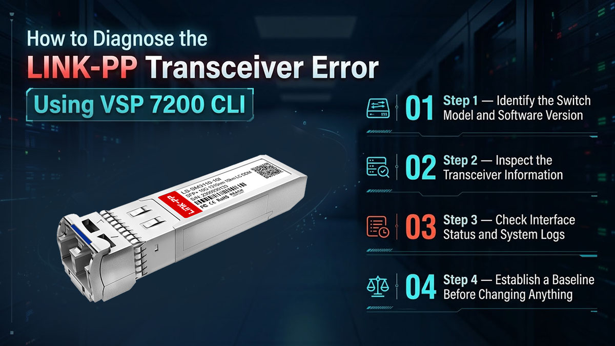
How to Diagnose the Transceiver Error Using VSP 7200 CLI
The most reliable way to diagnose an “Unsupported Transceiver” error on an Avaya VSP 7200 is to collect module identification data, check the affected interface, and inspect available optical diagnostics before changing the configuration. These checks help determine whether the switch recognizes the module, whether the port can establish a link, and whether the problem is related to transceiver support or physical connectivity. The commands below are documented for VOSS environments, but availability and output can vary by hardware model and software release.
Step 1 — Identify the Switch Model and Software Version
Start by recording the exact VSP 7200 model and installed VOSS software version. These details are necessary because transceiver restrictions and CLI capabilities may differ between hardware variants and software releases.
Before inspecting the module, collect the following information:
-
Hardware model: Identify the specific VSP 7200 variant and the affected slot and port.
-
Software version: Record the running VOSS release.
-
Module details: Note the transceiver's part number, serial number, and optical type from the module label or datasheet.
-
Failure timing: Determine whether the error appeared after module installation, a reboot, a software upgrade, or a change to the network configuration.
Use the system-information commands documented for the installed VOSS release to retrieve the model and software details. Do not assume that a command available on another VOSS version is supported on the device being diagnosed.
Once the baseline is recorded, use the module-identification commands to determine how the switch reads the installed transceiver.
Step 2 — Inspect the Transceiver Information
The VOSS command show pluggable-optical-modules basic displays basic transceiver information, including available manufacturing details and module characteristics. Run it first to establish whether the switch can retrieve identification data from the inserted module.
Enter privileged EXEC mode and run:
enable
show pluggable-optical-modules basic
To inspect a particular port, specify its slot and port identifier using the syntax supported by the installed release:
show pluggable-optical-modules basic 1/1
(Here, 1/1 is an illustrative port identifier; replace it with the actual slot and port.)
Review the available output for:
-
Vendor name and identification information.
-
Module part number and serial number.
-
Transceiver type and other reported characteristics.
-
Any recognition or status information exposed by the installed software.
If more detailed information is available, run:
show pluggable-optical-modules detail
The detailed command provides additional diagnostic information for supported module types, but the fields shown can depend on the platform and transceiver. Do not assume that every third-party module will expose every diagnostic field.
Compare the returned information with the exact manufacturer datasheet. Correctly populated identification fields suggest that the switch can read the module, but they do not establish that the module is officially supported or that the optical link is functioning.
Step 3 — Check Interface Status and System Logs
After identifying the module, check whether the affected interface is administratively enabled and operationally up. The interface state and corresponding system messages help distinguish a transceiver recognition warning from a port initialization failure or an optical connectivity problem.
Use the interface-status and logging commands documented for your VOSS release. Record the output for the affected port and look for the following conditions:
-
Interface administratively disabled: Check the port configuration before investigating optical hardware.
-
Interface enabled but operationally down: Investigate transceiver restrictions, remote-end status, and physical connectivity.
-
Unsupported-transceiver message: Record the exact message and when it appeared relative to module insertion or system startup.
-
Optical signal alarms: Check whether the port reports low receive power, transmit-power alarms, or other diagnostic warnings.
-
Repeated link transitions: Determine whether the connection repeatedly establishes and loses the link.
Correlate the timestamps of the logs with the interface status and transceiver information. A vendor-recognition warning alone does not establish the cause of a link failure; an optical power alarm, for example, may indicate a fiber-path problem that requires separate investigation. Available diagnostic fields depend on the transceiver and platform.
Step 4 — Establish a Baseline Before Changing Anything
Before reseating the module, replacing the fiber, or changing the configuration, preserve the initial diagnostic results. A baseline makes it easier to identify which action changes the error and reduces the risk of introducing additional variables during troubleshooting.
Record the following information in the incident notes:
-
Switch model, VOSS version, slot, and port.
-
The installed module's part number and serial number.
-
Output from the basic and detailed transceiver commands, where available.
-
Interface status and relevant system messages.
-
Local and remote optical standards, fiber type, and link configuration.
-
Any recent hardware, software, or configuration changes.
Keep the original output so that it can be compared with subsequent test results. If a second module or port is tested, document that change separately rather than changing several components at once.
With this baseline established, the next step is to compare the observed behavior against the module's specifications and the applicable hardware compatibility restrictions. This helps determine whether the error reflects a recognition policy, a port limitation, or a separate physical-link problem.
How to Check LINK-PP 10G SFP+ Compatibility with Avaya VSP 7200
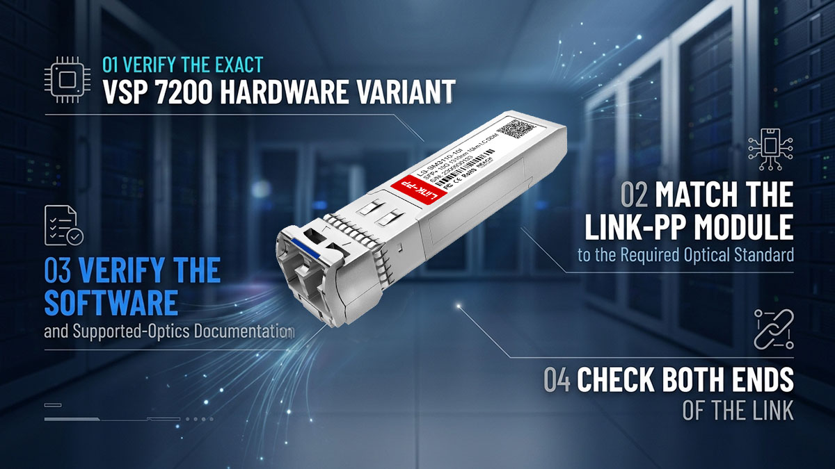
To verify whether the LINK-PP 10G SFP+ module is compatible with an Avaya VSP 7200, check the exact switch model, VOSS software release, port capabilities, module specifications, and remote-end configuration. A module that fits the SFP+ port and supports 10Gbps is not automatically supported by every hardware variant. Historical VOSS documentation also distinguishes between transceivers that are recognized but reported as unsupported and modules that cannot bring a port operationally up under specific platform restrictions.
Verify the Exact VSP 7200 Hardware Variant
Start with the switch's full model number rather than relying on the VSP 7200 family name alone. Different variants can have different port types, hardware limitations, and requirements for particular transceiver technologies.
Check these hardware details before evaluating the inserted optic:
-
Switch model: Confirm whether the platform is a VSP 7254XSQ, VSP 7254XTQ, or another applicable configuration.
-
Port type: Verify that the target interface supports the intended SFP+ transceiver and operating rate.
-
Port availability: Check whether the port is enabled and, on port-licensed models, whether the required license is active.
-
Hardware restrictions: Review the restrictions applicable to the exact model, especially for optical technologies that require specific signal-processing capabilities.
For example, the VSP 7254XSQ has documented restrictions on certain 10GBASE-LRM and 10GBASE-ZR/ZW transceivers because of its PHYless architecture. These restrictions apply to specific transceiver types and should not be interpreted as a blanket prohibition on all third-party 10G SFP+ modules.
Once the hardware model and port capability are established, compare them with the exact module part number. This avoids treating a general platform warning as proof that the selected module is unsuitable.
Match the Transceiver to the Required Optical Standard
The optical module must match the intended Ethernet standard and the optical requirements of the connection. Check the exact part number and datasheet rather than relying on a generic description such as “10G SFP+.”
Use the following parameters to evaluate the physical and optical match:
-
Data rate: Confirm support for the required 10Gbps interface
-
Optical standard: Match the required standard, such as 10GBASE-SR or 10GBASE-LR
-
Wavelength: Verify the specified wavelength and compatibility with the remote optic
-
Fiber type: Confirm multimode fiber for SR applications or suitable single-mode fiber for LR applications
-
Transmission distance: Ensure the link length falls within the module's rated reach
-
Connector: Check connector type and fiber termination
-
Optical budget: Confirm that the available power budget is sufficient for the link
These parameters determine whether the module is suitable for the optical connection, but they do not establish whether the switch accepts the module under its transceiver-support policy. For example, two 10G SFP+ modules can use the same physical interface but support different wavelengths, fiber types, and transmission distances.
For BiDi connections, verify that the local and remote modules use complementary transmit and receive wavelengths. For duplex SR or LR connections, confirm that the fiber type, connector arrangement, and optical specifications match at both ends.
Verify the Software and Supported-Optics Documentation
Compatibility must also be checked against the VOSS release installed on the switch. Transceiver handling can differ by software version, and historical documentation describes both forgiving and strict operating modes for different module categories on the VSP 7200 platform.
Before deployment, verify the following:
-
Record the installed VOSS software version.
-
Consult the transceiver compatibility information applicable to the exact switch model and release.
-
Check for explicit restrictions involving the module's optical technology or hardware requirements.
-
Determine whether an unsupported status represents a recognition warning or a restriction that prevents the port from operating.
-
Review relevant release notes if the warning appeared after a software upgrade.
Do not assume that a module supported on one VSP 7200 variant or software release will behave identically on another. Likewise, a module's absence from a supported-optics list does not, by itself, establish that the module cannot function; it may instead indicate that its operation is not officially qualified or supported.
Check Both Ends of the Link
Even when the optic is suitable for the local switch, the connection may fail if the remote interface or optical path is incompatible. Verify the complete link rather than diagnosing the local transceiver in isolation.
Check the following at both endpoints:
-
Interface speed: Confirm that both ports support the intended operating rate.
-
Transceiver type: Verify that both ends use compatible optical standards.
-
Wavelength arrangement: Confirm matching wavelengths for duplex links or complementary wavelengths for BiDi links.
-
Fiber path: Check fiber type, polarity, connector condition, and transmission distance.
-
Interface configuration: Review administrative state and applicable speed or autonegotiation settings.
-
Optical diagnostics: Where available, compare transmit power, receive power, and alarm status.
Pay particular attention to 1Gbps SFP modules installed in SFP/SFP+ interfaces. The VSP 7254XSQ has specific autonegotiation limitations for 1Gbps fiber modules, so the remote-end settings must be checked against the applicable platform documentation. These conditions should not be generalized to all 10Gbps SFP+ links.
After completing these checks, compare the results with the original CLI output. If the switch recognizes the module but reports it as unsupported while the link remains operational, investigate the support classification separately from physical performance. If the interface remains down, use the hardware, software, and optical findings to isolate the restriction or fault before proceeding with corrective actions.
Step-by-Step Troubleshooting for an Unsupported LINK-PP Transceiver
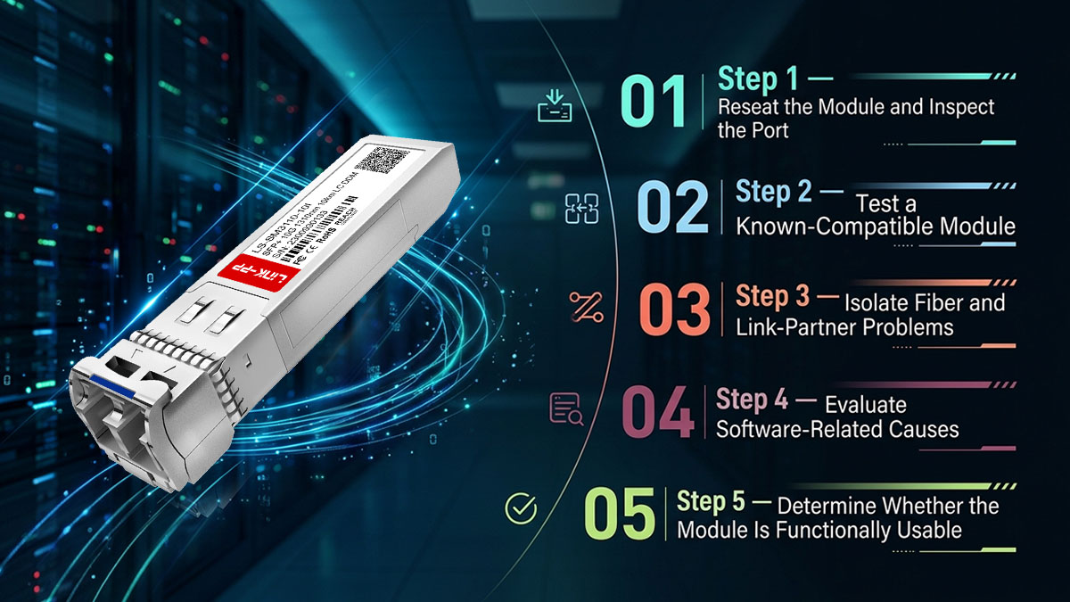
To troubleshoot an unsupported LINK-PP transceiver on an Avaya VSP 7200, begin with low-risk checks, isolate the module from the port and fiber path, and verify the result after each action. Do not assume that the warning requires a software change or module replacement: the cause may be a documented hardware restriction, a recognition issue, or a separate optical-link fault. Record the original CLI output before making changes, and use only commands supported by the installed VOSS release.
Step 1 — Reseat the Module and Inspect the Port
Reseating the module can resolve an intermittent detection problem caused by incomplete seating, but it will not resolve a genuine platform compatibility restriction. Before handling the transceiver, follow the switch's installation procedures and any applicable service precautions.
Perform these checks:
-
Record the original error message and port status.
-
If the port carries production traffic, arrange an approved maintenance window before disturbing the connection.
-
Remove and reseat the module according to the hardware installation instructions.
-
Inspect the module housing, latch, and accessible optical connectors for visible damage or contamination.
-
Recheck the module identification output and interface status after reinsertion.
If the switch now identifies the module consistently, determine whether the port establishes a stable link. If the same unsupported message returns, compare the module's identification information with the platform's documented restrictions before repeating the procedure.
A successful reseat can indicate a contact or detection issue, but it does not prove that the module is officially supported. Persistent recognition warnings require further investigation.
Step 2 — Test a Known-Compatible Module
Testing a known-compatible module in the affected port helps establish whether the problem follows the uncertified transceiver or remains associated with the port. Use a module documented as compatible with the exact VSP 7200 model and installed software release.
Follow this controlled test sequence:
-
Record the original transceiver's identification data and the current port state.
-
Install the known-compatible module using the approved procedure.
-
Check module recognition and interface status.
-
If permitted, test the third-party module in another suitable port with the same relevant capabilities.
-
Compare the results without changing multiple variables simultaneously.
Interpret the results carefully. If the known-compatible module works but the installed module consistently triggers the warning, investigate the module's recognition status and platform compatibility. If both modules fail in the same port, examine port configuration, hardware condition, and the physical link. If the third-party module works in another port, compare the capabilities and configuration of the two interfaces.
Step 3 — Isolate Fiber and Link-Partner Problems
If the optical module is detected but the interface remains down, inspect the optical path and remote endpoint. A fiber fault, incompatible optical standard, or mismatched link configuration can prevent communication even when the local transceiver is recognized.
Check the following components systematically:
-
Fiber cable: Confirm that the cable type and transmission distance match the module specifications.
-
Connector condition: Inspect and clean fiber connectors using appropriate procedures and equipment.
-
Fiber polarity: Verify that the local transmit path connects to the remote receive path and vice versa.
-
Remote transceiver: Confirm that the remote module uses a compatible optical standard and wavelength arrangement.
-
Optical power: Where digital diagnostic monitoring (DDM) is available, compare measured transmit and receive power with the module's specified operating range.
-
Remote interface: Check whether the other port is enabled, operational, and configured for the intended speed.
When the receive-power reading is abnormally low, test a known-good fiber cable and inspect the connectors before concluding that the transceiver has failed. A zero or unusually low receive-power reading can indicate a broken fiber, a non-operational remote transmitter, or a connection problem. Conversely, excessive receive power can indicate an optical mismatch or receiver saturation.
If the optical readings and physical connection appear normal but the unsupported message persists, return to the platform's transceiver-support requirements. Optical troubleshooting can explain a link failure, but it cannot by itself remove a vendor-recognition warning.
Step 4 — Evaluate Software-Related Causes
If the error appeared after a VOSS upgrade or configuration change, investigate whether the change affected module recognition or port behavior. Software-related issues should be confirmed through release documentation and repeatable observations rather than assumed from timing alone.
Use this process to narrow down the cause:
-
Record the exact installed VOSS version and the first occurrence of the warning.
-
Compare the current behavior with the relevant release notes and known compatibility restrictions.
-
Check whether the module's reported identification data or the interface state changed after the upgrade.
-
Verify whether the current hardware and software combination supports the intended optical technology.
-
Consult the applicable support guidance before considering an upgrade, downgrade, or configuration change.
Do not downgrade the software, alter undocumented settings, or attempt to bypass transceiver checks solely to suppress the warning. Such actions may introduce additional risks without resolving the underlying compatibility issue.
If the software release is not identified as the cause, continue with hardware and module isolation. If the issue appears to be release-specific, preserve the logs and diagnostic output so the behavior can be evaluated against the relevant software documentation.
Step 5 — Determine Whether the Module Is Functionally Usable
The final diagnostic step is to establish whether the third-party transceiver can maintain a working link and pass traffic, even if the switch continues to report it as unsupported. Functional operation and official platform support are separate considerations, so both must be documented.
Use the following verification checks:
-
Module recognition: Repeat the transceiver information command and confirm whether the module's identification fields remain consistent.
-
Interface state: Verify that the port is operationally up and does not repeatedly transition between up and down.
-
Optical diagnostics: Review available transmit power, receive power, temperature, and alarm readings.
-
Traffic performance: Check interface counters and, where operationally appropriate, validate traffic in both directions.
-
Support limitations: Determine whether the warning reflects an unresolved qualification restriction or a documented limitation that prevents normal operation.
If the module maintains a stable link and passes traffic without abnormal errors, the evidence supports functional operation under the tested conditions. It does not establish official qualification or guarantee continued operation after a software or hardware change.
If the port remains down, the warning persists alongside initialization failures, or optical readings fall outside the specified range, do not classify the issue as resolved. Continue with the relevant compatibility checks or escalate the case with the collected diagnostic information.
Common LINK-PP and Avaya VSP 7200 Troubleshooting Scenarios
These 10G SFP+ modules can produce different symptoms on an Avaya VSP 7200, and each symptom points to a different area of investigation. A module that is detected but marked unsupported requires a different response from one that is not detected at all or one that is recognized while the link remains down. Compare the switch’s module information, port status, system logs, and optical diagnostics before deciding on a corrective action.
Scenario 1 — The Module Is Recognized but Marked Unsupported
When the VSP 7200 displays module identification information but reports the 10G SFP+ module as unsupported, the switch is detecting the transceiver but may not recognize it as an approved or qualified option. This warning alone does not prove that the module is defective or that the optical link cannot operate.
Start by collecting the module details and confirming the exact switch model and software release. Then check whether the module’s identification data and specifications match the requirements for that platform.
Recommended checks include:
-
Run show pluggable-optical-modules basic to review the module information reported by the switch.
-
Run show pluggable-optical-modules detail to inspect additional transceiver details where supported.
-
Verify the module’s exact part number, data rate, optical standard, wavelength, and transmission distance.
-
Check the applicable compatibility documentation for the specific hardware variant and software release.
-
Review system logs for messages that clarify whether the warning relates to module qualification, identification, or another condition.
If the module is recognized and the port is operational, record that result separately from its support status. Successful operation under current conditions does not establish official compatibility or guarantee operation after a software upgrade. If the port remains down, continue troubleshooting the interface and optical path rather than assuming the warning is the only cause.
Scenario 2 — The Module Is Not Detected or Identification Data Is Missing
If the VSP 7200 does not detect the inserted module or cannot display its identification information, investigate the physical connection, module seating, port condition, and possible hardware faults first. This symptom differs from an unsupported-module warning because the switch may not be reading enough information to evaluate compatibility.
Begin with a low-risk physical inspection and compare the affected port with a known-working port or a known-compatible module, if available.
-
Confirm that the module is fully inserted and its latch is secured.
-
Inspect the module and port for visible damage, contamination, or obstruction.
-
Reseat the module according to the platform’s installation guidance, following appropriate precautions for live equipment.
-
Re-run show pluggable-optical-modules basic and, where appropriate, show pluggable-optical-modules detail.
-
Check whether the same module is detected in another supported port, or whether a known-compatible module is detected in the original port.
The results help narrow the cause. If the transceiver is not detected in multiple suitable ports but a known-compatible module is detected normally, the module itself or its identification interface may require further investigation. If multiple modules fail to appear in one port, focus on the port, switch hardware, or platform-specific limitations. Missing identification data should not be treated as proof of a vendor-compatibility restriction without additional evidence.
Scenario 3 — The Module Is Recognized but the Link Remains Down
When the switch recognizes the 10G SFP+ module but the interface does not establish a link, the next step is to investigate the optical connection, remote-end configuration, and interface state. Module recognition confirms that the switch can read transceiver information; it does not confirm that optical signals are reaching the remote device or that both endpoints can establish the link.
Check the local and remote ends together, since a fault on either side can prevent link establishment.
-
Verify that both endpoints support the configured link rate and the selected optical standard.
-
Confirm that the fiber type and connector arrangement match the module specifications.
-
Check fiber polarity and ensure that the transmit and receive paths are correctly connected.
-
Inspect and clean fiber connectors using appropriate procedures.
-
Review available digital diagnostic monitoring (DDM) readings, especially transmit and receive optical power, if supported and enabled.
-
Compare interface status and relevant logs on both endpoints.
A receive-power reading that is very low or zero may indicate a disconnected or damaged fiber, incorrect polarity, or a problem with the remote transmitter. An optical-power reading within range does not by itself prove that the link should come up; both endpoints must also support compatible signaling and link settings.
If the optical path appears healthy, test with a known-compatible module or known-good fiber where practical. Change one variable at a time so that the results distinguish an optical-path issue from a port, remote-end, or module-related problem.
Scenario 4 — The Error Appears After a Software Upgrade
If the Unsupported Transceiver message begins appearing after a VSP 7200 software upgrade, compare the new software release with the previous environment before changing the hardware. A release change can affect module recognition, diagnostics, or compatibility behavior, but the timing alone does not prove that the upgrade caused the issue.
Use the following checks to establish whether the software change is relevant:
-
Record the current software version and, if available, the version used before the upgrade.
-
Compare the current module status with saved CLI output or maintenance records from before the change.
-
Review the release notes and compatibility information applicable to the exact switch model and software release.
-
Check system logs for new warnings or changes in the way the module is reported.
-
Confirm whether the port’s operational state has changed, or whether only the displayed support status is different.
If the module is still detected and the link remains operational, document the new warning and verify the status against the applicable support guidance. If the port has stopped working, investigate the link and interface conditions as well as the recognition message.
Do not downgrade software or attempt to bypass transceiver qualification checks solely to remove the warning. Any software change should follow the platform’s supported upgrade or recovery procedure, with configuration backups and an appropriate maintenance plan.
Scenario 5 — The Same Module Behaves Differently Across Ports
If the same 10G SFP+ module is recognized in one VSP 7200 port but marked unsupported or not detected in another, investigate port-specific capabilities, hardware differences, and physical conditions. Different results do not automatically mean that either the module or the switch is faulty.
Use a controlled comparison to determine whether the symptom follows the module or remains with the port.
-
Confirm that both ports are intended to support the same module type and optical standard.
-
Check whether the ports belong to different hardware groups or have different documented capability restrictions.
-
Compare the module information reported by each port using the supported pluggable-optics commands.
-
Inspect the affected port and module seating, and check relevant logs for port-specific messages.
-
Where operationally safe, test a known-compatible module in the affected port and test the unverified module in another suitable port.
Interpret the pattern of results carefully. If the same module works in one port but is not detected in another, prioritize port condition, seating, and hardware capability checks. If it is detected in both ports but marked unsupported in each, investigate platform qualification and software compatibility. If recognition is consistent but the link comes up on only one port, compare optical connections, interface settings, and remote-end conditions.
Document the exact port numbers, module part number, software release, reported status, and test results. This evidence makes it easier to identify a repeatable port-specific issue and provides useful information for further technical support.
How to Verify the Fix and Prevent Recurring Transceiver Errors
After troubleshooting a LINK-PP 10G SFP+ module on an Avaya VSP 7200, verify both transceiver recognition and actual link performance before considering the issue resolved. Clearing the Unsupported Transceiver warning is not sufficient if the port remains down, optical power is abnormal, or traffic is unstable. A reliable verification process should confirm module status, interface operation, traffic behavior, and repeatable results.
Confirm Module Recognition and Port State
The first verification step is to confirm that the VSP 7200 detects the optical module and reports a consistent status after the corrective action. Compare the new results with the diagnostic output collected before troubleshooting to determine which conditions have changed.
Use the supported CLI commands for the installed software release:
-
Run show pluggable-optical-modules basic to review the module information reported by the switch.
-
Run show pluggable-optical-modules detail to inspect additional transceiver information where supported.
-
Check the relevant interface status using the appropriate interface command for the installed VOSS release.
-
Review system logs for recurring transceiver warnings, detection failures, or interface events.
-
Confirm whether the module’s recognition status has changed and whether the interface is operational.
The expected result is consistent module detection, an appropriate interface state, and no new errors that indicate an unresolved fault. If the module remains marked unsupported but the port operates normally, document the warning separately and confirm the platform’s compatibility requirements rather than treating the warning as resolved.
Validate Link Stability and Traffic Performance
A port that comes up immediately after troubleshooting is not necessarily stable. Verify that the optical link remains established and that traffic passes normally over a reasonable observation period under representative network conditions.
Check the physical link and traffic behavior from both endpoints where possible. The following checks help distinguish a successful fix from a temporary recovery.
-
Link stability: Confirm that the interface remains up and does not repeatedly transition between up and down.
-
Optical diagnostics: Review transmit and receive power readings when DDM is supported and enabled, comparing them with the module’s specifications and the optical link budget.
-
Error counters: Inspect available interface statistics for increasing errors, drops, or other abnormal indicators.
-
Remote-end status: Confirm that the peer interface is operational and uses a compatible optical standard and link configuration.
-
Traffic verification: Test expected connectivity and representative traffic flows across the link.
Interpret the results together rather than relying on a single status indicator. A stable interface with normal traffic and no increasing error counters provides stronger evidence of successful operation than module recognition alone. If the link continues to flap or errors increase, return to the relevant troubleshooting branch and investigate the optical path, port, or remote endpoint.
Create a Repeatable Compatibility Record
A compatibility record helps prevent the same transceiver issue from recurring during future installations, hardware replacements, or software upgrades. Documenting the tested configuration also gives administrators a reliable baseline for comparing behavior when a similar warning appears.
For each validated deployment, record the following information:
-
Exact VSP 7200 hardware model and affected port.
-
VOSS software release and relevant configuration details.
-
Module part number and available identification information.
-
Optical standard, wavelength, fiber type, connector, and rated transmission distance.
-
Initial error message, diagnostic output, and relevant system logs.
-
Corrective actions performed and the resulting module and interface status.
-
Optical diagnostic readings, traffic test results, and any remaining compatibility warnings.
Keep the record specific to the tested hardware, software, module, and link configuration. Successful operation on one switch or port should not automatically be treated as proof of compatibility across every VSP 7200 variant. Before future upgrades or deployments, compare the planned configuration with the recorded results and check the applicable compatibility documentation.
A repeatable verification process makes it easier to distinguish a genuine hardware or optical fault from a transceiver qualification warning. It also provides a clear basis for deciding whether the installed transceiver can remain in service under the tested conditions or whether further compatibility confirmation is needed.
Avaya VSP 7200 Unsupported Transceiver Troubleshooting Checklist
Use this troubleshooting checklist to confirm that the key diagnostic steps have been completed before closing an incident. The goal is to identify whether the LINK-PP 10G SFP+ issue involves module recognition, platform compatibility, port condition, software behavior, or the optical link. Complete the checks in sequence and record any unresolved warnings rather than assuming that a detected module is fully compatible.
Essential Checks Before Closing the Troubleshooting Case
Before closing the case, verify that the module has been inspected, the switch has reported its identification information, and the link has been tested under the intended operating conditions. A complete record should distinguish the switch’s support status from the actual operational state of the interface.
Use the following checklist to review the investigation:
-
Confirm the exact Avaya VSP 7200 hardware model and installed VOSS software release.
-
Record the 10G SFP+ module’s exact part number and available identification details.
-
Run show pluggable-optical-modules basic and review the reported module information.
-
Run show pluggable-optical-modules detail if supported and additional diagnostic information is needed.
-
Check the interface state and relevant system logs for detection errors, unsupported-module warnings, or link events.
-
Confirm that the module is fully seated and that the port and connectors show no obvious physical issues.
-
Verify the data rate, optical standard, wavelength, fiber type, connector, and rated transmission distance.
-
Check compatibility information for the exact switch variant and software release.
-
Inspect the remote endpoint, fiber polarity, and available optical power readings.
-
Test with a known-compatible module or known-good fiber when necessary and operationally safe.
-
Confirm link stability, traffic behavior, and available interface error counters after the fix.
-
Document any remaining warning and determine whether further compatibility confirmation is required.
Completing these checks provides evidence for deciding whether the problem has been corrected or remains unresolved. If the module operates normally but is still marked unsupported, retain that distinction in the incident record and confirm its support status before treating the deployment as fully validated.
Quick Reference — Symptom, Likely Cause, and Next Action
The quickest way to select the next diagnostic step is to match the observed symptom with the most likely cause and then perform a test that can distinguish between competing explanations. The reference below summarizes common patterns without assuming that any single symptom proves a specific fault.
| Observed symptom | Likely cause to investigate | Recommended next action |
| Module detected but marked unsupported | Qualification policy, module identification, or software compatibility | Check the exact hardware model, software release, and applicable compatibility documentation |
| Module not detected | Poor seating, port condition, or module identification failure | Reseat the module safely and compare detection with a known-compatible module |
| Module detected but link remains down | Fiber, polarity, remote optic, or interface configuration | Check both endpoints, fiber connections, interface state, and optical diagnostics |
| Receive optical power is very low or zero | Disconnected or damaged fiber, polarity issue, or remote transmitter problem | Inspect the optical path and compare readings at both endpoints where available |
| Warning appeared after a software upgrade | Changed recognition behavior or release-specific compatibility | Compare software versions, logs, and applicable release documentation |
| Same module behaves differently across ports | Port-specific restrictions, physical condition, or hardware differences | Compare port capabilities and test the module in another suitable port |
Use these symptom patterns as diagnostic guidance rather than definitive fault classifications. For example, low receive power can point to an optical-path problem, while an unsupported warning may remain even when a link operates. Each conclusion should be supported by module information, port status, optical readings, or controlled test results.
The case is ready to close when the corrective action has been verified, link performance is stable under the intended conditions, and the final module support status is documented. If compatibility remains uncertain or the warning persists without a clear explanation, retain the diagnostic evidence and escalate the case to the appropriate technical support team instead of relying solely on successful link operation.
Conclusion
The Avaya VSP 7200 Unsupported Transceiver error does not necessarily indicate a defective LINK-PP 10G SFP+ module or a failed optical link. In many cases, the issue is related to transceiver qualification, hardware-specific restrictions, software compatibility, or module identification. A systematic approach to Avaya VSP 7200 transceiver compatibility helps administrators distinguish an unsupported status from a detection failure or an actual link problem.
Before considering the troubleshooting complete, keep these essential points in mind:
-
Verify the exact VSP 7200 hardware model and VOSS software release.
-
Check LINK-PP module identification data and optical specifications.
-
Use VSP 7200 CLI commands and system logs to investigate recognition and port status.
-
Isolate module, port, fiber, and remote-end issues through controlled testing.
-
Confirm link stability and traffic performance, and document any remaining compatibility warnings.
Choosing the right optical module also means considering product quality, compatibility information, and after-sales support. The LINK-PP Official Store provides standard-stock products with a 15-day no-reason return policy, while covers return shipping costs when a product has a quality issue. Review the module specifications and confirm compatibility with your exact Avaya VSP 7200 configuration before deployment. With careful verification and clear support policies, network teams can reduce deployment risks and maintain more reliable optical connectivity.