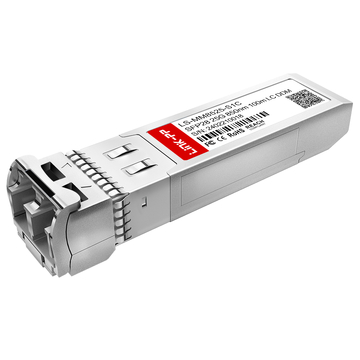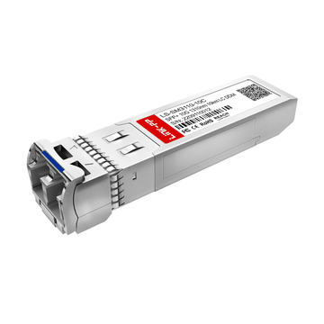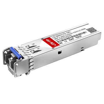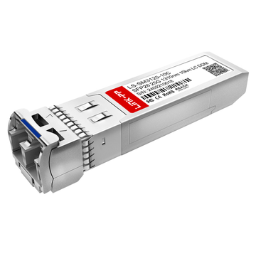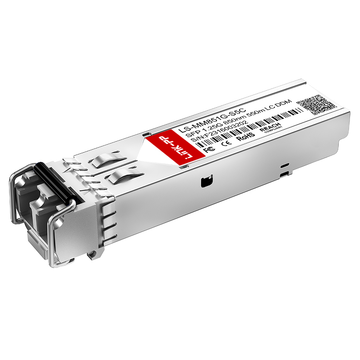
SFP electrical connector is the host-side 20-contact, 0.8 mm card-edge interface that mates with an SFP-family module through the cage. It carries high-speed differential data, low-speed control lines, power, and management signals. In SFP + hosts, the low-speed interface is based on 3.3 V LVTTL, and the high-speed path is built around 100 Ω differential signaling.
:contentReference[oaicite:0]{index=0}Although many engineers use the term “SFP connector” loosely, the host-side receptacle is defined as part of a 0.8 mm card-edge connector system. SNIA separates the connector, cage, and module into different specifications, and newer pluggable generations such as SFP28, SFP56, and SFP112 extend that same family while relying on higher-level standards such as IEEE or FC-PI for performance requirements.
:contentReference[oaicite:1]{index=1}In practice, this means the connector choice is not just a mechanical decision. It affects signal integrity, EMI behavior, grounding strategy, insertion force, and Печатные платы footprint constraints. For that reason, a correct comparison of SFP, SFP+, and later-generation interfaces must look at both electrical signaling and mechanical implementation.
В этом руководстве объясняется следующее:
- Что такое электрический разъем SFP и где он располагается в стеке портов?
- Чем отличаются SFP, SFP+ и SFP28 на уровне сигнала?
- Какие контакты передают данные, питание, управление и выполняют функции администрирования?
- как разъем соотносится с корпусом и модулем
- Что наиболее важно для компоновки печатной платы, заземления и контроля электромагнитных помех?

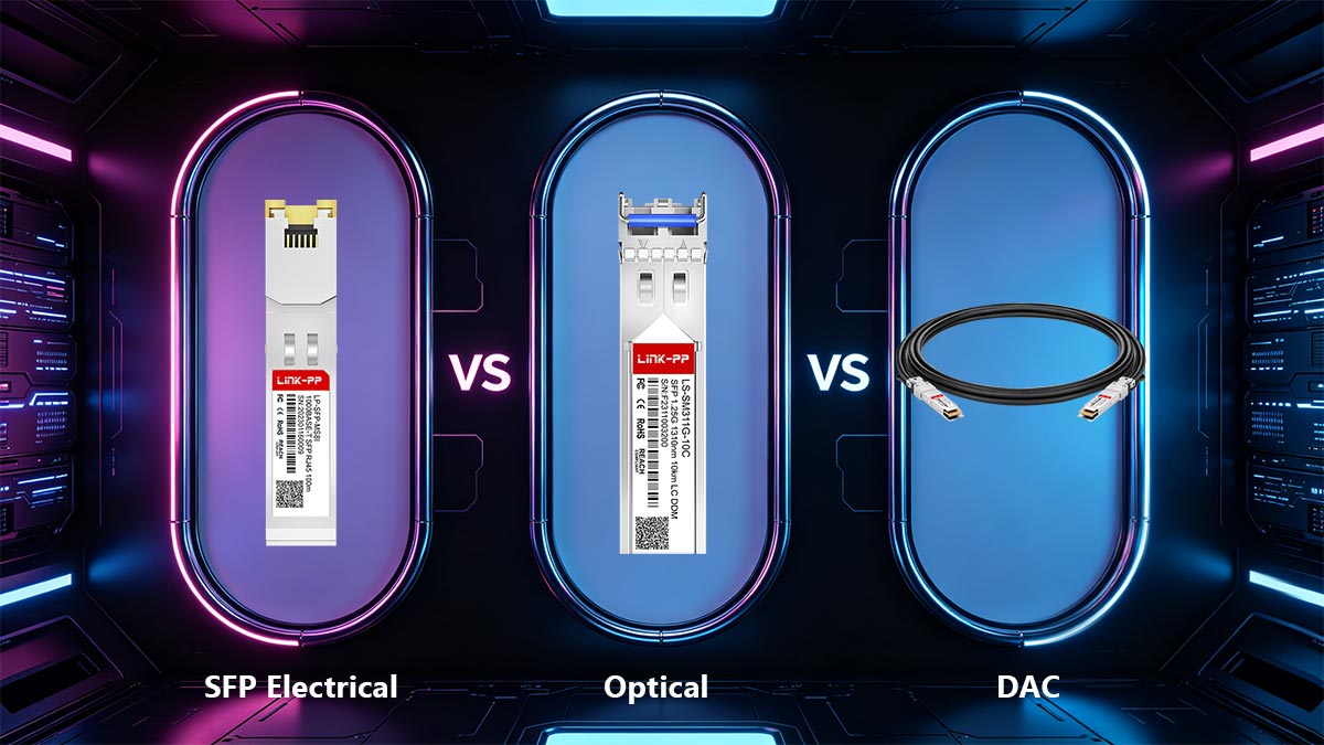
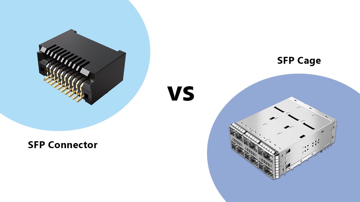
⏩ Разъем SFP против корпуса SFP: в чем разница?
Электрический разъем SFP — это контактный интерфейс, монтируемый на печатной плате, который передает данные, питание, заземление и сигналы управления между хост-системой и модулем. Корпус SFP — это металлическая конструкция, которая удерживает модуль на месте, обеспечивает отверстие для установки и помогает в борьбе с электромагнитными помехами. Другими словами, разъем обеспечивает электрическое соединение, а корпус выполняет механическую функцию и функцию экранирования.
| Компонент | Главная роль | Что оно делает | Чего оно не делает |
|---|---|---|---|
| Электрический разъем SFP | Электрический интерфейс | Взаимодействует с краевыми контактами модуля и передает сигналы со стороны хоста. | Модуль не удерживается механически. |
| Клетка SFP | Механическая + экранирующая конструкция | Направляет при вставке, обеспечивает надежную фиксацию и помогает ограничить утечку электромагнитных помех. | Не обеспечивает передачу сигнала самостоятельно. |
Это различие имеет значение при проектировании оборудования. Разъем SFP является частью компоновки материнской платы и расположен под корпусом. Корпус и разъем указаны как единая система в механической документации SFP, поэтому при правильном проектировании порта необходимо учитывать как совместимость, так и целостность сигнала.
Механическая ретенция
Клетка — это деталь, которая придает разъему его физическую форму и обеспечивает выравнивание модуля во время установки и извлечения. Она также работает вместе с защелкой или язычком на модуле, обеспечивая фиксацию. Сам по себе разъем не может надежно удерживать модуль на месте.
EMI экранирование
Клетка помогает сформировать проводящий корпус вокруг отверстия модуля, что снижает утечку электромагнитных помех и улучшает непрерывность экранирования на порту. Это особенно важно при высоких скоростях передачи данных, когда порт должен сохранять качество сигнала, одновременно ограничивая излучение и восприимчивость к помехам.
Электрический контакт
Разъем — единственная деталь, которая фактически передает электрический интерфейс от модуля к печатной плате. Он обеспечивает высокоскоростные линии передачи/приема, питание, заземление и низкоскоростные линии управления. Без разъема корпус представлял бы собой лишь механическую оболочку.
Практический вывод: когда инженеры говорят «порт SFP», они часто имеют в виду всю сборку, включающую корпус и разъем. Но для компоновки, закупки и устранения неполадок полезно разделять функции: корпус удерживает и экранирует кабель, а разъем обеспечивает соединение.
⏩ Основные сведения о посадочном месте, размерах и компоновке печатной платы разъема SFP
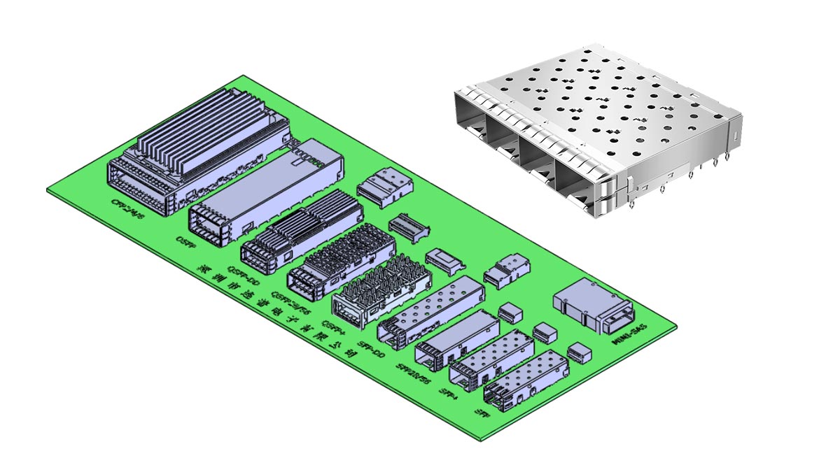
Разъем SFP для подключения модуля представляет собой угловой разъем, монтируемый на печатную плату и соединяющийся с контактной площадкой модуля внутри корпуса. Семейство SFP использует шаг контактов 0.8 мм, 20 контактов и последовательный порядок соединения: сначала подключается заземление, затем питание, а затем сигнальные контакты. Система разъемов разработана как часть платы и корпуса модуля, а не как отдельный компонент.
Монтажный стиль
В спецификации разъема SFP+ разъем на стороне платы представляет собой 1 × 0.8 мм разъем на краю платы с угловым гнездом в корпусе. Контактная площадка на основной плате включает в себя установочные штыри и заданный рисунок контактных площадок с шагом контактов 0.80 мм в каждом ряду, расстоянием между рядами 0.40 мм и типичным расстоянием между штырями 9.60 мм.
Зона запрета
Плата модуля с контактными площадками требует минимальной площади, исключающей контакт компонентов/паяльной маски, 5.50 мм. Геометрия контактов также определяет начальные точки для областей заземления и питания, что помогает предотвратить попадание паяльной маски и обеспечивает надежный контакт по краям во время установки.
Вопросы компоновки плат-носителей
Для надежной работы порта SFP плата должна соответствовать указанной последовательности контактов: сначала заземление, затем питание, и только потом сигнал. Также необходима защитная клетка или защелкивающаяся конструкция, которая будет направлять плату модуля в разъем, обеспечивать достаточную очистку контактов и создавать жесткий упор, чтобы модуль не упирался в разъем. Контакт экрана защитной клетки должен замыкаться до сигнальных контактов и размыкаться последним, чтобы уменьшить электростатический разряд и разницу потенциалов между корпусами.
Краткое описание практического применения: Правильная конфигурация разъема SFP — это не просто схема расположения контактных площадок. Это согласованный набор параметров: геометрия разъема, контроль за доступом, выравнивание корпуса и последовательность контактов. При проектировании печатной платы наиболее безопасный подход — использовать точную конфигурацию разъема от производителя вместе с механическими ограничениями SFF, а затем проверить глубину установки, расположение штифтов и выравнивание корпуса относительно платы перед выпуском.
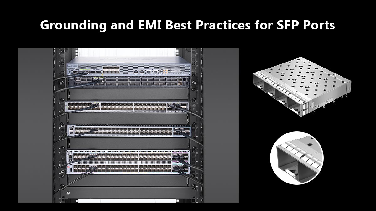
⏩ Рекомендации по заземлению и электромагнитной совместимости для портов SFP
Наиболее безопасная стратегия заземления SFP-модулей заключается в том, чтобы рассматривать корпус и экран как заземление шасси, отделять их от заземления цепи и использовать низкоимпедансный путь к корпусу. В стандарте SFP MSA прямо указано, что заземление шасси и внешние экраны от электромагнитных помех не должны подключаться к заземлению цепи, а также рекомендуется отключать сигналы разъема при извлечении трансивера для повышения защиты от электромагнитных помех.
Для высокоскоростных схем в порту следует использовать короткие, согласованные дифференциальные дорожки, надлежащее соединение проводников Vcc и GND, а также стандартные методы трассировки с контролируемым импедансом. Электрическая спецификация SFP+ рекомендует использовать короткие и одинаковые по длине дифференциальные сигнальные линии, микрополосковую трассировку там, где это необходимо, и оконечные резисторы 50 Ом на стороне хоста.
Заземление экрана
Металлический экранирующий кожух должен обеспечивать непрерывный путь экранирования вокруг отверстия модуля и соединяться с шасси с помощью низкоиндуктивного соединения. Это помогает снизить уровень излучаемых помех и повысить устойчивость к внешним шумам. На практике экран должен обеспечивать надежный контакт с отверстием порта и избегать использования длинного пути обратной связи сигнал-земля для контроля электромагнитных помех.
Соединение шасси
Do не tie the cage or external shield directly into noisy circuit ground. Instead, reference the shield to chassis or enclosure ground so high-frequency currents can return through the mechanical shell rather than through sensitive signal reference planes. This separation is a core EMC principle and is specifically called out in the SFP MSA.
Шумоподавление для высокоскоростных каналов связи
Обеспечьте короткие, симметричные и контролируемые импедансные пары TX/RX, а развязку питания размещайте близко к разъему и микросхеме хоста. Спецификация SFP+ также отмечает, что низкоскоростные и силовые интерфейсы являются частью электрической схемы на стороне хоста, поэтому качество компоновки напрямую влияет на стабильность канала связи и запас по электромагнитным помехам.
Практический вывод
Хорошо спроектированный SFP-порт должен соответствовать трем правилам: заземление корпуса на шасси, изоляция экрана от заземления цепи и прокладка высокоскоростных пар проводников со строгим контролем импеданса. При правильном выполнении этих трех условий порт с гораздо большей вероятностью будет соответствовать целевым показателям электромагнитной совместимости и поддерживать стабильную работу на высоких скоростях.
⏩ Часто задаваемые вопросы о типах электрических разъемов SFP и сигналах
1. Электрический разъем SFP — это то же самое, что и корпус SFP?
Нет. Разъем и защитный кожух выполняют разные функции. Разъем обеспечивает электрический интерфейс, а защитный кожух — механическую фиксацию, направление модуля и экранирование от электромагнитных помех. Полный порт SFP обычно содержит оба компонента.
2. Сколько контактов у разъема SFP?
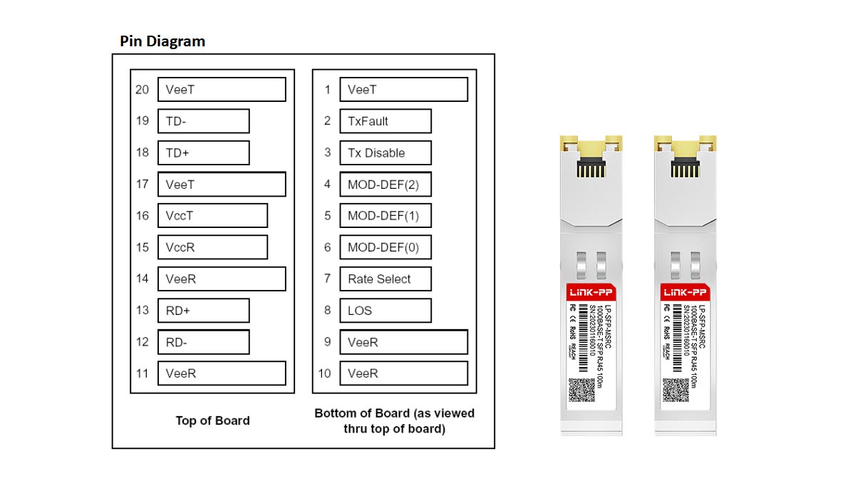
Электрический разъем SFP использует 20-контактный интерфейс , основанный на конструкции с шириной контакта 0.8 мм. Эти контакты обеспечивают передачу данных, подачу питания, заземление, управление модулями и мониторинг состояния.
3. Какие сигналы проходят через электрический разъем SFP?
Разъем содержит:
- TX± дифференциальные сигналы передачи
- RX± дифференциальные сигналы приема
- Шины питания Vcc
- Ориентиры на местности
- сигналы управления SDA и SCL
- TX_DISABLE
- TX_FAULT
- Rx_LOS (Потеря сигнала)
Вместе эти сигналы обеспечивают связь, диагностику и возможность «горячей» замены.
4. Могут ли модули SFP, SFP+ и SFP28 использовать один и тот же тип разъема?
Да. SFP, SFP+ и SFP28 используют аналогичную архитектуру 20-контактного механического разъема. Однако для высокоскоростных приложений требуется более жесткий контроль целостности сигнала, улучшенная конструкция печатной платы и производительность разъема, способная поддерживать целевую скорость передачи данных.
5. Передает ли разъем SFP оптические сигналы?
Нет. Разъем передает только электрические сигналы. Оптическая передача происходит внутри приемопередающего модуля, где электрические сигналы преобразуются в оптические и передаются через волоконно-оптический интерфейс.
6. Почему заземление важно в конструкции SFP-портов?
Надлежащее заземление улучшает электромагнитную совместимость, снижает шумовую связь и помогает защитить от электростатического разряда (ESD). В соответствии с передовой отраслевой практикой, экранирующий кожух подключается к заземлению шасси, при этом необходимо поддерживать контролируемые пути возврата сигнала на печатной плате.
7. Какая самая распространенная ошибка при проектировании интерфейса хоста SFP?
Одна из самых распространенных ошибок — рассматривать разъем SFP как чисто механический компонент. Высокоскоростные интерфейсы SFP требуют тщательного внимания к дифференциальному импедансу, согласованию длины дорожек, стратегии заземления, интеграции в корпус и целостности питания для обеспечения надежной работы.
⏩ Как выбрать подходящий электрический разъем SFP
Выбор подходящего электрического разъема SFP зависит от четырех практических факторов: скорость передачи данных, место на плате, требования к соответствию стандартам и стратегия закупок.. Для СФП 1G designs, standard SFP connectors are usually sufficient. For 10G, 25G, and faster platforms, the connector must support tighter signal integrity, stronger EMI control, and a validated cage-to-board layout. The safest choice is a connector that matches the target speed class, PCB footprint, and mechanical specification of the final system.
1) Начните с целевой скорости передачи данных.
Первым делом вам следует определиться с требуемым скоростным классом.
- 1G SFP для устаревшего или универсального Ethernet
- 10G SFP + для массовых высокоскоростных сетей
- 25G SFP28 для новых проектов центров обработки данных и доступа
Более высокие скорости предъявляют более жесткие требования к потерям на входе, контролю импеданса и качеству разводки печатной платы. Разъем, хорошо работающий на скорости 1 Гбит/с, может не подойти для конструкции, рассчитанной на 25 Гбит/с.
2) Проверьте наличие свободного места на плате.
Порты SFP компактны, но для полной сборки всё равно потребуется достаточно места для:
- посадочное место разъема
- корпус клетки
- недоступность
- пространство для установки защелки и модуля
- трассировка дорожек на печатной плате хоста
Если плата имеет высокую плотность размещения компонентов, выбор разъемов следует сопоставить с геометрией корпуса и компоновкой передней панели, прежде чем окончательно утвердить проект.
3) Проверить соответствие требованиям
Для серийного оборудования разъем должен соответствовать соответствующим механическим и электрическим характеристикам SFP. Это включает в себя:
- секвенирование контактов
- Ожидаемые значения дифференциальной маршрутизации 100 Ом
- поведение заземления и экрана
- надежность горячей замены
- совместимость с предполагаемым семейством модулей
Compliance is especially important in products that must pass EMC, совместимость, or carrier-grade validation.
4) Разработайте стратегию закупок.
Выбор разъема — это не только техническое решение. Он также влияет на сроки поставки, доступность и стабильность долгосрочных поставок. Для OEM- и ODM-проектов лучше выбирать компонент, который:
- широко доступный
- документировано с четкими данными о следах
- совместим с целевой клеткой
- поддерживается надежным производителем
Для команд, которые закупают готовые модули SFP или строят систему на основе проверенной экосистемы, LINK-PP Официальный магазин Это удобное место для изучения совместимых модулей SFP и связанных с ними решений для сетевого подключения.
Контрольный список для окончательного отбора
Воспользуйтесь этим простым правилом, прежде чем окончательно утвердить дизайн:
- Сначала выбирайте по скорости.
- Во-вторых, убедитесь в соответствии габаритов и размера клетки.
- Проверьте электромагнитную совместимость и заземление.
- Выбирайте надежного поставщика в последнюю очередь.
Заключение
Качественный электрический разъем SFP — это тот, который одновременно соответствует вашим электрическим требованиям, механическим ограничениям и потребностям в электропитании. Для стабильной работы и упрощения развертывания всегда оценивайте разъем как часть всей системы портов SFP, а не как отдельный компонент.