






The rapid expansion of artificial intelligence (AI), high-performance computing (HPC), and hyperscale data centers is pushing network bandwidth requirements beyond the capabilities of conventional 400G and 800G infrastructures. As GPU clusters process increasingly complex workloads, network switches must deliver higher throughput while maintaining port density, power efficiency, and reliable connectivity.
OSFP224 addresses this demand through the next-generation OSFP1600 platform, which supports 200G-per-lane signaling across eight high-speed electrical lanes to deliver an aggregate bandwidth of 1.6Tbps. This transition involves more than doubling transmission speed. It also introduces new requirements for electrical interfaces, optical components, signal integrity, and thermal management.
This guide explores the key technologies behind OSFP224 and explains what changes when networking moves to 200G per lane. Specifically, it covers:
-
OSFP224 architecture and its position in the 1.6T networking roadmap.
-
Differences between 100G and 200G-per-lane signaling.
-
Electrical interfaces, SerDes, and signal integrity requirements.
-
Optical architectures, fiber connectivity, and transmission distances.
-
Power consumption, thermal management, and platform compatibility.
-
Practical deployment considerations and the role of high-speed optical transceivers.
Understanding these changes helps network engineers evaluate 1.6T connectivity requirements and prepare data center infrastructure for the next generation of high-bandwidth networking.
What Is OSFP224 and Why Does 200G per Lane Matter?
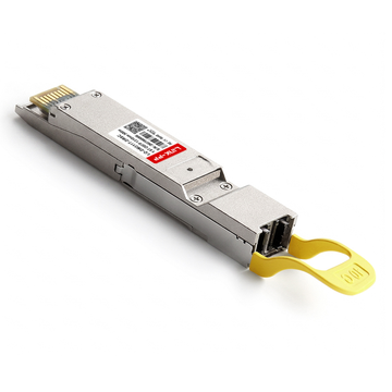
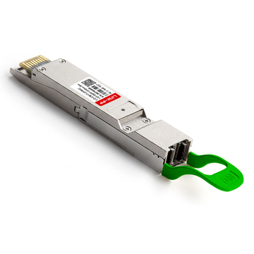
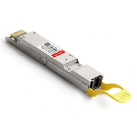
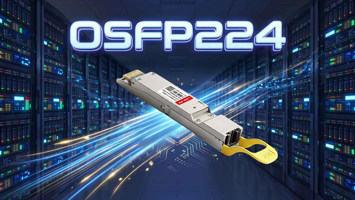
OSFP224 is commonly used to describe the 200G-per-lane generation of the OSFP pluggable transceiver platform, formally identified in the OSFP MSA as OSFP1600. It supports eight 200G-class electrical lanes, providing up to 1.6Tbps of aggregate bandwidth in a single module.
Unlike earlier OSFP generations, which primarily supported 50G or 100G per lane, OSFP224 is designed for significantly higher electrical signaling rates and the more demanding optical connectivity requirements of next-generation data centers.
Understanding the OSFP224 Form Factor
OSFP stands for Octal Small Form-factor Pluggable. It is a high-density, hot-pluggable transceiver form factor developed for high-speed networking applications.
OSFP224 represents the 200G-per-lane evolution of this platform. Its formal OSFP MSA designation is OSFP1600, reflecting its maximum aggregate bandwidth of 1.6Tbps.
Its main characteristics include:
-
Eight high-speed electrical lanes: Each lane supports 200G-class signaling.
-
1.6Tbps aggregate bandwidth: Eight lanes provide the total 1.6T capacity.
-
Hot-pluggable design: Modules can be inserted or removed without requiring the entire networking system to be powered down, subject to host platform procedures.
-
Advanced thermal design: Integrated heat sinks or riding heat sink configurations help manage higher power dissipation.
-
CMIS management support: Enables module identification, configuration, monitoring, and diagnostics.
-
Multiple optical interfaces: Depending on the implementation, modules can use MPO/MTP or duplex LC connectors.
The OSFP1600 specification also defines mechanical, electrical, connector, PCB, and thermal requirements. Therefore, OSFP224 is not simply an existing OSFP module operating at a higher speed. It requires corresponding improvements throughout the host and module interfaces.
Why the Industry Is Moving Beyond 800G
The transition from 800G to 1.6T is primarily driven by the growing bandwidth demands of AI infrastructure and large-scale data center networking.
Modern AI clusters connect thousands of GPUs through high-performance switching fabrics. As distributed training workloads increase, the network must transfer enormous volumes of data between compute nodes while minimizing communication bottlenecks.
Several factors are accelerating the move toward 1.6T:
-
AI and GPU networking: Distributed AI training requires high-bandwidth connections between GPU servers and network switches.
-
Hyperscale infrastructure: Cloud providers need greater switching capacity without continuously increasing rack space and port counts.
-
Higher traffic density: Modern data centers must support more traffic through increasingly compact networking equipment.
-
Power efficiency: Increasing bandwidth per port can help improve system-level bandwidth density, although actual power savings depend on the complete platform design.
-
Network scalability: Higher-capacity optical interfaces provide more flexibility when expanding large switching fabrics.
For example, an 800G switch port provides 800Gbps of aggregate capacity, while a 1.6T port doubles that capacity within a single port position.
This increase allows network architects to design higher-capacity switching systems without relying exclusively on adding more physical ports.
How OSFP224 Fits into the 1.6T Networking Roadmap
The evolution of optical transceivers has increasingly focused on raising the bandwidth of individual electrical lanes.
A simplified progression illustrates how this development has occurred:
| Networking Generation | Lane Configuration | Aggregate Bandwidth |
|---|---|---|
| 400G OSFP | 8 × 50G | 400G |
| 800G OSFP | 8 × 100G | 800G |
| OSFP1600 / OSFP224 | 8 × 200G | 1.6T |
Each generation increases the bandwidth supported by an individual electrical lane while maintaining an eight-lane architecture.
OSFP224 is therefore an important step in the transition toward 1.6T Ethernet and InfiniBand connectivity.
It also exists alongside alternative packaging approaches, including OSFP-XD. However, these platforms use different mechanical and electrical designs and should not be treated as interchangeable.
The broader direction is clear: higher per-lane bandwidth is becoming essential for increasing network capacity while maintaining high-density switch architectures.
100G vs. 200G per Lane: What Actually Changes?
The transition from 100G to 200G per lane doubles the nominal bandwidth of each electrical lane, but it also significantly increases the demands placed on signal transmission, modulation, and hardware design.
OSFP224 uses 200G-class lanes to achieve 1.6Tbps aggregate throughput. This requires faster SerDes interfaces, improved signal integrity, and more advanced signal processing compared with conventional 800G platforms.
Lane Rate and Aggregate Bandwidth Comparison
The primary difference between 100G and 200G-per-lane architectures is the amount of data each electrical channel can carry.
An eight-lane 800G interface provides eight 100G-class lanes. An OSFP1600 interface doubles the nominal capacity of each lane to reach 1.6Tbps.
The relationship can be expressed as:
-
8 × 50G = 400G
-
8 × 100G = 800G
-
8 × 200G = 1.6T
This approach increases total bandwidth without doubling the number of electrical lanes.
It is important to distinguish between nominal lane bandwidth, gross signaling rate, and usable payload throughput. Encoding, framing, and forward error correction introduce overhead, so these figures should not be treated as identical.
112G PAM4 vs. 224G PAM4 Signaling
PAM4, or four-level Pulse Amplitude Modulation, is a key technology enabling high-speed electrical and optical communication.
Unlike NRZ modulation, which uses two signal levels to represent one bit per symbol, PAM4 uses four amplitude levels to encode two bits per symbol.
This allows PAM4 to transmit twice as many bits per symbol without requiring the same proportional increase in symbol rate.
The transition from 112G-class to 224G-class signaling can be understood through the following comparison:
| Parameter | 112G-Class PAM4 | 224G-Class PAM4 |
|---|---|---|
| Nominal signaling generation | 112G | 224G |
| PAM levels | 4 | 4 |
| Bits per symbol | 2 | 2 |
| Approximate symbol rate | 56GBd | 112GBd |
| Symbol interval | 17.78ps | 8.89ps |
| Typical application | 100G-class lane | 200G-class lane |
The symbol rate is approximately doubled, while the modulation format remains PAM4.
This distinction matters because 224G refers to the electrical signaling generation, not a 224GBd symbol rate. Actual line rates and symbol rates depend on the specific interface and implementation.
At higher signaling speeds, each symbol occupies a shorter time interval. Consequently, timing errors, noise, and signal distortion have less room for tolerance.
Forward error correction (FEC) becomes increasingly important for maintaining reliable data transmission. It helps detect and correct transmission errors, improving link reliability despite the more demanding electrical channel conditions.
What Higher Lane Speeds Mean for Network Design
Moving to 200G per lane creates several new engineering challenges.
The electrical channel must preserve signal quality across the entire path between the switch ASIC and the optical module.
Key considerations include:
-
Insertion loss: Higher-frequency signals experience greater attenuation through PCB traces, connectors, and other passive components.
-
Return loss: Impedance discontinuities can cause signal reflections that interfere with data transmission.
-
Crosstalk: Closely spaced high-speed electrical lanes can introduce unwanted interference.
-
Jitter: Timing variations become more significant as the unit interval becomes shorter.
-
Noise sensitivity: PAM4 uses four signal levels with smaller voltage separation than a comparable NRZ signal.
-
FEC requirements: More advanced error correction may be necessary to maintain the required link performance.
These challenges mean that 200G-per-lane networking cannot rely on simply increasing the operating speed of existing 800G hardware.
Instead, the entire electrical channel, including the switch ASIC, PCB, connector, and optical module, must be designed and validated for the target signaling generation.
OSFP224 Electrical Architecture and Signal Integrity Requirements
OSFP224 requires a high-performance electrical architecture capable of supporting 200G-class data transmission across eight lanes. The switch ASIC, SerDes, PCB traces, connectors, and module interface must operate together as a carefully engineered high-speed channel.
At these speeds, signal integrity is a system-level requirement rather than an isolated component specification.
224G Electrical Interface and SerDes Requirements
SerDes, short for Serializer/Deserializer, converts parallel data into high-speed serial streams for transmission and reconstructs the data at the receiving end.
In an OSFP224 system, the host switch ASIC uses advanced SerDes technology to communicate with the optical module through eight high-speed electrical lanes.
The electrical architecture must support:
-
Eight 200G-class transmit lanes.
-
Eight corresponding receive lanes.
-
High-speed PAM4 signaling.
-
Accurate clock and data recovery.
-
Advanced equalization and error management.
-
Electrical characteristics that comply with the relevant host-to-module interface requirements.
The OSFP MSA defines the electrical interface, pin assignments, host connector, and mechanical requirements for OSFP1600.
Meanwhile, industry electrical interface specifications address the signal transmission requirements between the switch ASIC and the pluggable module.
The distinction is important: the OSFP form factor defines the module interface, while the SerDes and electrical channel determine whether the host can reliably communicate at the required speed.
Signal Integrity Challenges at 224G
Signal integrity becomes more difficult as electrical signaling rates increase.
At 224G-class signaling, the shorter unit interval leaves less time for the receiver to distinguish between valid signal transitions.
Several engineering techniques help address these challenges.
-
Advanced equalization: Feed-forward equalization (FFE) and decision-feedback equalization (DFE) compensate for channel distortion.
-
Impedance control: Consistent impedance across PCB traces and connectors reduces signal reflections.
-
Low-loss PCB materials: High-performance laminate materials help reduce attenuation at higher frequencies.
-
Crosstalk reduction: Optimized trace spacing, grounding, and routing help minimize interference between adjacent channels.
-
Clock and data recovery: Accurate timing recovery helps receivers interpret incoming signals correctly.
-
FEC: Error correction improves link reliability when electrical noise and distortion cannot be completely eliminated.
The OIF CEI-224G framework identifies channel bandwidth, insertion loss, modulation, equalization, and FEC as important considerations for next-generation electrical interfaces.
These requirements explain why 224G networking places significantly greater demands on hardware design and validation.
The Role of OSFP Connectors, Cages, and PCB Design
The connector and cage assembly is another important part of the OSFP224 electrical architecture.
Even when the transceiver itself supports 200G per lane, poor electrical performance at the host connector or PCB interface can prevent the system from achieving reliable operation.
Important design considerations include:
-
Connector impedance: The connector must maintain consistent electrical characteristics across high-speed contacts.
-
Contact geometry: Contact dimensions and spacing influence insertion loss and crosstalk.
-
PCB footprint: The host PCB layout must follow the applicable OSFP1600 mechanical and electrical requirements.
-
Signal routing: High-speed differential pairs require controlled impedance and carefully managed routing paths.
-
Mechanical tolerances: Accurate module and cage alignment ensures reliable electrical contact.
-
Thermal and airflow design: Cage geometry must also accommodate the cooling requirements of high-power modules.
The OSFP1600 specification includes dedicated mechanical and PCB requirements, reflecting the changes needed to support the higher-speed generation.
For system designers, this means that connector selection, cage design, and PCB validation must be considered together rather than independently.
OSFP224 Optical Architecture: From Electrical Lanes to Optical Transmission
OSFP224 converts high-speed electrical signals from the host switch into optical signals for transmission through fiber, then performs the reverse conversion at the receiving end.
Although the electrical interface supports eight 200G-class lanes, the optical architecture can vary depending on the intended transmission distance, fiber infrastructure, and port configuration.
Common approaches include DR8, 2×DR4, and 2×FR4.
How 200G Electrical Lanes Connect to Optical Lanes
An OSFP224 optical transceiver contains several key components that work together to convert electrical data into optical signals.
The basic transmission process involves:
-
The host switch ASIC generates eight high-speed electrical data streams.
-
The electrical signals enter the OSFP224 module through its high-speed connector.
-
The DSP or corresponding signal-processing architecture prepares the data for optical transmission.
-
Laser drivers control the optical transmit components.
-
Optical engines convert the electrical signals into optical signals.
-
The optical signals travel through fiber to the receiving transceiver.
-
Photodetectors and transimpedance amplifiers (TIAs) convert incoming optical signals back into electrical signals.
Depending on the transceiver architecture, optical conversion may use silicon photonics, EML lasers, or other optical integration technologies.
The relationship between electrical and optical lanes is not always a simple one-to-one connection at the system level. The final mapping depends on the optical PMD and port configuration.
Key 1.6T Optical Interface Architectures
Different 1.6T optical architectures are designed for different network topologies and fiber requirements.
Three important configurations are DR8, 2×DR4, and 2×FR4.
| Optical Architecture | Optical Configuration | Fiber Type | Representative Maximum Reach |
|---|---|---|---|
| 1.6T DR8 | 8 parallel 200G optical lanes | SMF | 500m |
| 1.6T 2×DR4 | 2 independent 800G DR4 links | SMF | 500m |
| 1.6T 2×FR4 | 2 independent 800G FR4 links using wavelength multiplexing | SMF | 2km |
Note: These are representative implementation distances. Actual specifications depend on the transceiver design and applicable optical PMD requirements.
1. 1.6T DR8
DR8 uses eight parallel optical channels to transmit 1.6Tbps over single-mode fiber.
Its main characteristics include:
-
Eight optical lanes operating at 200G-class rates.
-
Parallel optical transmission.
-
MPO-based fiber connectivity.
-
Typical reach of up to 500m in relevant implementations.
This architecture is suitable for high-bandwidth connections within data center environments.
2. 1.6T 2×DR4
The 2×DR4 architecture provides two independent 800G DR4 optical connections through one OSFP224 module.
Its characteristics include:
-
Two separate four-lane optical links.
-
Eight optical lanes in total.
-
Dual MPO optical interfaces in representative implementations.
-
Typical reach of up to 500m.
This configuration is particularly useful when network architects need two independent 800G connections from a single 1.6T module position.
3. 1.6T 2×FR4
The 2×FR4 architecture uses wavelength-division multiplexing to transmit multiple optical channels through fiber.
Its main characteristics include:
-
Two independent FR4 optical links.
-
Four wavelength channels per link.
-
Duplex LC connectivity in representative implementations.
-
Single-mode fiber transmission.
-
Typical reach of up to 2km.
Unlike parallel DR8 and DR4 architectures, FR4 combines multiple optical wavelengths into fewer fiber strands, making it useful for applications where fiber connectivity and transmission distance are important considerations.
The choice between these architectures depends on link distance, existing fiber infrastructure, switch configuration, and network topology.
Fiber Connectivity and Optical Interface Considerations
The optical connector must match the transceiver architecture and the fiber infrastructure.
For OSFP224 deployments, MPO/MTP and duplex LC are two important connectivity options.
MPO/MTP connectivity
MPO connectors are commonly used in parallel optical architectures such as DR8 and 2×DR4.
Important considerations include:
-
Fiber count and connector configuration.
-
Male and female connector compatibility.
-
Fiber polarity.
-
Key orientation and alignment.
-
Insertion loss and return loss.
-
Connector cleanliness.
Duplex LC connectivity
Duplex LC connectors are commonly associated with wavelength-multiplexed FR4 architectures.
Their advantages include:
-
Compatibility with established duplex single-mode fiber infrastructure.
-
Simpler fiber connectivity compared with high-count parallel optical connectors.
-
Convenient integration into existing LC-based patching systems.
Regardless of the connector type, fiber inspection and cleaning are essential.
At 1.6T transmission rates, optical link performance depends on more than the transceiver specifications. Connector contamination, excessive insertion loss, incorrect polarity, and poor fiber installation can all cause link failures.
Power Consumption and Thermal Management at 1.6T
Power consumption and thermal management are major considerations for OSFP224 because higher-speed electrical and optical components generate additional heat.
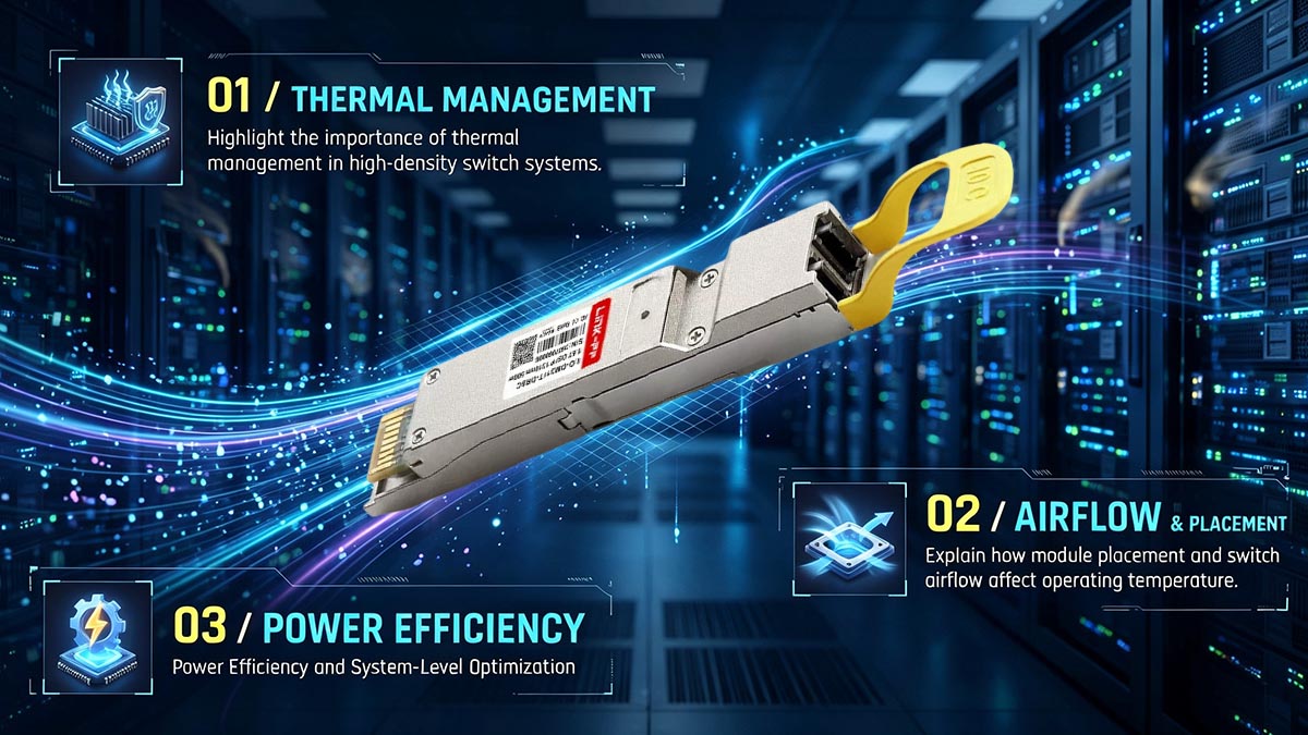
The OSFP1600 platform includes enhanced power delivery and cooling provisions to support high-power modules, making host chassis airflow and module thermal design critical to reliable operation.
Why OSFP224 Modules Require More Advanced Thermal Design
Higher data rates require more sophisticated electronic and optical components.
These components can contribute significantly to overall module power consumption.
Major heat-generating components include:
-
High-speed DSPs and signal-processing circuits.
-
Laser drivers and optical transmit components.
-
Photodetectors and receiver electronics.
-
Clock and data recovery circuits.
-
Power regulation and management components.
The OSFP MSA Revision 5.22 specifies a maximum power capability of up to 42.9W for OSFP1600.
This is a platform-level maximum, not a statement that every OSFP224 transceiver consumes 42.9W. Actual module power depends on its optical architecture, DSP implementation, and design.
Higher power density creates several thermal challenges:
-
Maintaining the required module case temperature.
-
Preventing excessive heating of DSP and optical components.
-
Preserving signal quality under sustained operating conditions.
-
Avoiding thermal throttling or protective shutdown.
-
Maintaining reliable operation across different chassis airflow conditions.
Consequently, thermal management must be considered during both transceiver selection and switch system design.
OSFP224 Cooling Solutions: Integrated Heat Sink and Airflow
The OSFP1600 platform supports different cooling configurations to accommodate high-power optical modules.
Two important approaches are Integrated Heat Sink (IHS) and Riding Heat Sink (RHS).
Integrated Heat Sink (IHS)
An IHS module incorporates its own heat sink into the transceiver assembly.
Its main characteristics include:
-
Heat dissipation through the module's integrated cooling structure.
-
Compatibility with appropriately designed OSFP cages.
-
Dependence on chassis airflow for effective cooling.
-
Different heat sink geometries depending on module power requirements.
Riding Heat Sink (RHS)
An RHS design transfers heat from the module to a heat sink integrated into the host system.
Its characteristics include:
-
Thermal contact between the module and host cooling structure.
-
Greater dependence on host-level mechanical and thermal design.
-
Potential advantages for systems with specialized cooling arrangements.
-
Specific cage and mechanical requirements.
One important compatibility distinction is that standard OSFP and OSFP-RHS modules are not mechanically interchangeable.
The chassis must support the corresponding cooling architecture.
In addition to the heat sink, airflow direction and velocity affect cooling performance. Network engineers should evaluate module placement, cage ventilation, fan capacity, and the thermal behavior of densely populated switch ports.
Power Efficiency and System-Level Optimization
Power efficiency becomes increasingly important as data center bandwidth increases.
A network switch equipped with multiple 1.6T optical modules can consume a substantial amount of power, making module efficiency an important part of the overall system power budget.
Several approaches can help improve efficiency:
-
DSP optimization: Advanced signal processing can improve the balance between performance and power consumption.
-
Retiming architecture: Fully retimed, transmit-retimed, and linear approaches provide different trade-offs in signal conditioning, reach, and power.
-
Optical integration: Silicon photonics and other integrated optical technologies can improve component integration and potentially reduce implementation complexity.
-
Cooling optimization: Efficient airflow and thermal management help prevent unnecessary cooling overhead.
-
Power monitoring: Monitoring module power consumption helps network operators understand system-level energy requirements.
It is important to evaluate power efficiency at both the module and system levels.
A lower-power transceiver is not automatically the best option if it cannot satisfy the required reach, signal integrity, or interoperability requirements.
The most suitable solution must balance bandwidth, power consumption, thermal performance, and network reliability.
OSFP224 Compatibility, Management, and Deployment Considerations
OSFP224 compatibility depends on more than the physical form factor. The host switch must support the required electrical interface, data rate, module power class, cooling configuration, and management functions.
For network engineers evaluating a 1.6T upgrade, checking these requirements before deployment is essential to avoid module recognition problems, link instability, and thermal limitations.
OSFP224 Compatibility with Existing 400G and 800G Platforms
OSFP224 belongs to the OSFP1600 generation, but its compatibility with previous OSFP platforms should not be assumed.
The OSFP MSA distinguishes between OSFP, OSFP800, and OSFP1600 based on their supported lane rates and mechanical requirements.
Important compatibility considerations include:
-
Form factor: OSFP1600 has specific mechanical requirements that differ from earlier OSFP generations.
-
Electrical interface: A host supporting 100G-per-lane signaling does not automatically support 200G-per-lane operation.
-
Switch ASIC: The ASIC must support the required SerDes speed and port configuration.
-
Cage and connector: The host cage and electrical connector must meet the applicable OSFP1600 requirements.
-
Power delivery: The host must supply sufficient power for the selected module.
-
Thermal design: The chassis must support the module's cooling requirements.
-
Firmware: Host firmware and management software must recognize and properly configure the module.
OSFP224 should also be distinguished from QSFP-DD and OSFP-XD.
Although these form factors may serve similar high-bandwidth networking applications, they have different mechanical and electrical specifications.
OSFP and OSFP-XD are specifically defined as mechanically incompatible in the OSFP MSA.
Therefore, physical resemblance or similar bandwidth ratings are not sufficient evidence of interoperability.
CMIS Management and Digital Diagnostic Monitoring
CMIS, or Common Management Interface Specification, defines the management interface used by modern pluggable optical modules.
It allows network equipment to identify, configure, and monitor transceivers through a standardized management framework.
For OSFP224 deployments, CMIS-based management supports several important functions:
-
Module identification: Reports module type, manufacturer information, and supported capabilities.
-
Application configuration: Provides information about supported operating modes and data paths.
-
Power management: Supports module power-state control and monitoring.
-
Digital diagnostics: Provides operating information such as temperature, voltage, and optical power.
-
Alarm and warning monitoring: Helps identify abnormal operating conditions.
-
Module control: Supports configuration and management operations through the host interface.
Digital Diagnostic Monitoring (DDM) is particularly useful for maintaining optical link performance.
Common diagnostic parameters include:
| Diagnostic Parameter | What It Indicates |
|---|---|
| Module Temperature | Internal or reported module operating temperature |
| Supply Voltage | Module power supply condition |
| Laser Bias Current | Operating condition of the laser transmit circuitry |
| Tx Optical Power | Optical signal power transmitted by the module |
| Rx Optical Power | Optical signal power received by the module |
These measurements help network operators identify potential problems before they cause link failures.
For high-speed optical networks, monitoring individual lanes and relevant module alarms can provide additional insight into transmission performance.
Deployment Checklist for OSFP224 Networks
Successful OSFP224 deployment requires coordination between the optical module, switch platform, fiber infrastructure, and cooling system.
Before installation, network engineers should verify the following:
Host platform verification
-
Confirm that the switch supports OSFP1600 or the specific OSFP224 implementation.
-
Verify 200G-per-lane SerDes support.
-
Check the required port configuration and breakout modes.
-
Confirm firmware and management software support.
Electrical and mechanical verification
-
Check OSFP1600 cage and connector compatibility.
-
Verify host PCB and electrical channel requirements.
-
Confirm the supported power class.
-
Ensure that the module's cooling configuration matches the chassis.
Optical link verification
-
Match the optical PMD with the intended transmission distance.
-
Confirm single-mode or multimode fiber requirements.
-
Verify MPO/MTP or LC connector configurations.
-
Check fiber polarity, insertion loss, and optical power budgets.
-
Ensure that both ends of the link use compatible optical specifications.
Management and operational verification
-
Confirm CMIS support.
-
Check module identification and application configuration.
-
Verify FEC settings and link training where applicable.
-
Monitor temperature, voltage, and optical power.
-
Test link stability before production deployment.
A structured verification process reduces the risk of incompatibility and helps ensure reliable operation after installation.
How LINK-PP Supports High-Speed Optical Networking
As data center networks evolve toward higher transmission rates, selecting optical transceivers that match the host equipment and application requirements becomes increasingly important.
At LINK-PP, we focus on optical transceivers and high-speed connectivity solutions for enterprise networks, data centers, and other networking environments.
Our optical module portfolio covers different transmission rates, form factors, wavelengths, and fiber applications, helping network teams evaluate connectivity options for their existing infrastructure.
When selecting an optical transceiver, we recommend paying particular attention to:
-
Transmission rate: Ensure the module supports the required network speed and lane configuration.
-
Wavelength: Match the optical wavelength with the intended fiber infrastructure.
-
Transmission distance: Select an optical specification appropriate for the actual link length.
-
Connector type: Confirm compatibility with the installed fiber cabling.
-
Equipment compatibility: Verify the module's coding and operating requirements against the target switch or network device.
-
Operating conditions: Consider temperature range, power consumption, and cooling requirements.
For organizations currently operating 400G and 800G networks, these checks also provide a practical foundation for planning future 1.6T upgrades.
LINK-PP provides compatibility-oriented optical module selection and technical support to help customers identify suitable connectivity solutions for their networking environments.
As OSFP224 adoption develops, specific 1.6T module availability and compatibility should be verified against the relevant product specifications and host platform requirements rather than assumed from previous-generation OSFP support.
OSFP224 Applications and the Future of 1.6T Data Center Connectivity
OSFP224 is designed for high-bandwidth networking environments where traditional 800G connectivity may no longer provide sufficient capacity.
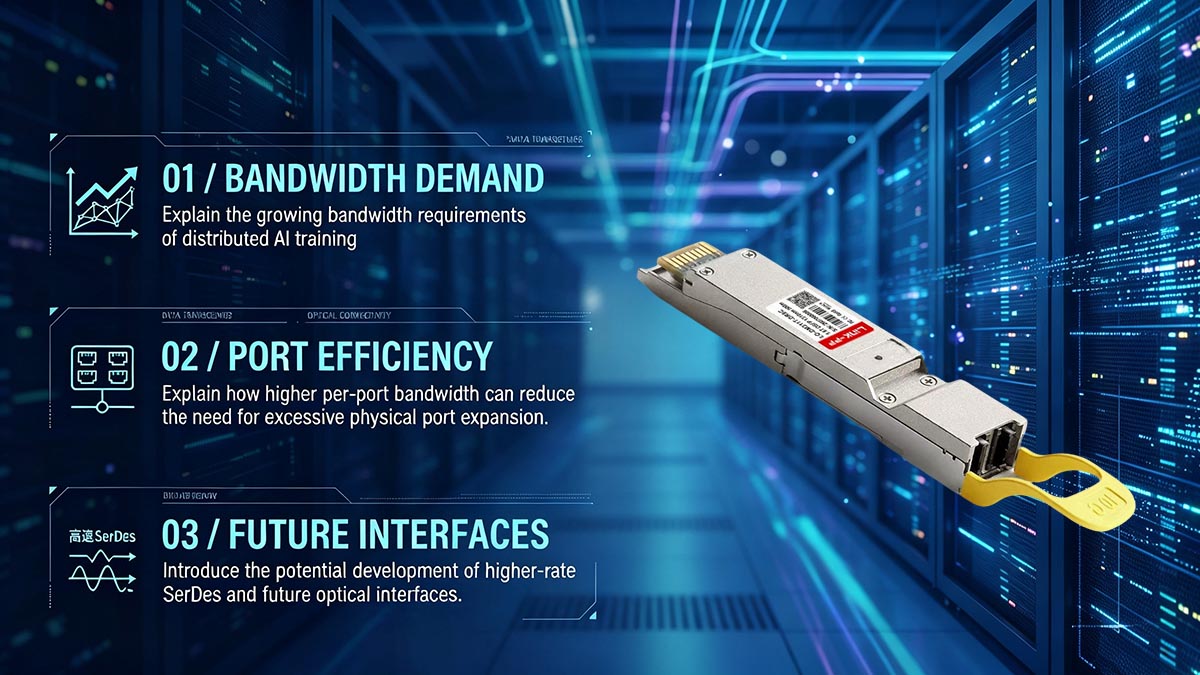
Its 1.6Tbps aggregate bandwidth makes it relevant to AI computing clusters, hyperscale data centers, and next-generation Ethernet and InfiniBand switching systems.
OSFP224 in AI and GPU Computing Clusters
AI training and inference workloads generate substantial traffic between GPUs, servers, and network switches.
As cluster sizes increase, network bandwidth becomes an important factor affecting overall system performance.
OSFP224 helps address these requirements by providing higher-capacity optical connections.
Its potential applications include:
-
GPU-to-switch connectivity: Supporting high-bandwidth connections between GPU servers and top-of-rack or aggregation switches.
-
AI scale-out networks: Providing high-capacity links between distributed compute nodes.
-
HPC infrastructure: Supporting data-intensive workloads that require fast communication between computing resources.
-
Large-scale AI clusters: Helping increase switching capacity while maintaining high port density.
-
InfiniBand fabrics: Supporting next-generation high-bandwidth interconnect environments.
For AI infrastructure, the value of 1.6T is not limited to the bandwidth of an individual optical module.
It also contributes to the design of larger switching fabrics with higher aggregate capacity.
Hyperscale Data Centers and Next-Generation Switching
Hyperscale data centers require network architectures that can scale with increasing traffic demands.
OSFP224 provides a higher-capacity port option for next-generation switches, helping network architects increase bandwidth density without relying exclusively on additional physical ports.
Potential advantages include:
-
Higher aggregate bandwidth per switch port.
-
Greater network capacity within a limited front-panel space.
-
Support for high-capacity spine-leaf network architectures.
-
More flexible 1.6T and dual-800G connectivity configurations.
-
Improved scalability for large cloud and enterprise data centers.
For example, a 2×DR4 OSFP224 implementation can provide two independent 800G optical connections through a single module position.
This architecture can simplify certain network topologies by consolidating two high-speed optical links within one module.
However, the actual benefits depend on switch architecture, port breakout capabilities, fiber infrastructure, and the intended network topology.
What Comes After 1.6T?
Although OSFP224 represents a major development in pluggable optical networking, the industry continues to explore technologies that can support even higher bandwidth and greater power efficiency.
Several developments are likely to influence future optical connectivity.
Higher-rate SerDes
Future SerDes generations will continue to increase per-lane bandwidth. Higher signaling rates will require further improvements in electrical channel design, signal processing, and connector technology.
Silicon Photonics
Silicon photonics integrates optical functions onto silicon-based platforms, helping improve optical integration and potentially supporting more scalable high-speed transceiver designs.
Co-Packaged Optics (CPO)
CPO places optical engines closer to switch ASICs, reducing the electrical distance between the switching silicon and optical conversion components.
This approach may help address electrical channel loss and power consumption challenges associated with extremely high-speed interfaces.
Linear Pluggable Optics (LPO)
LPO reduces or removes certain DSP functions within the optical module, allowing more signal processing to be handled by the host system.
This architecture can potentially reduce module power consumption and latency, although it places stricter requirements on host electrical signal quality.
These technologies are not direct replacements for every OSFP224 application. Instead, they represent different approaches to addressing the increasing bandwidth and efficiency demands of future data center networks.
For network operators, the most practical strategy is to evaluate current connectivity requirements while maintaining flexibility for future upgrades.
Conclusion
OSFP224 represents an important transition in high-speed optical networking, moving beyond 100G-per-lane architectures toward 200G-per-lane signaling and 1.6Tbps aggregate bandwidth.
However, this transition involves more than doubling transmission speed. It requires improvements in electrical interfaces, signal integrity, optical architecture, thermal management, and host platform compatibility.
The key takeaways are:
-
Eight 200G-class lanes: Deliver 1.6Tbps aggregate bandwidth through the OSFP1600 platform.
-
224G PAM4 signaling: Enables higher electrical throughput but introduces stricter signal integrity requirements.
-
Advanced optical architectures: DR8, 2×DR4, and 2×FR4 address different fiber connectivity and transmission distance requirements.
-
Thermal and power management: Higher-performance modules require carefully designed cooling and power delivery.
-
Platform compatibility: Host SerDes, cages, firmware, CMIS, and optical specifications must all be verified before deployment.
As AI infrastructure and hyperscale data centers continue to expand, 1.6T optical connectivity will become increasingly important in next-generation network architectures.
At LINK-PP, we continue to support network connectivity projects with optical transceivers designed for different transmission rates, equipment platforms, and fiber applications. Whether you are maintaining an existing 400G/800G network or evaluating the requirements for a future 1.6T upgrade, selecting the correct optical interface is essential.
Visit the LINK-PP Official Store to explore our optical module portfolio. You can use the Compatibility Tool to check equipment matching, or contact our team to obtain a sample quotation and technical assistance for your application.
For additional confidence, standard in-stock items are covered by a 15-day no-reason return and exchange policy. If a product has a quality issue, LINK-PP covers the return shipping cost.