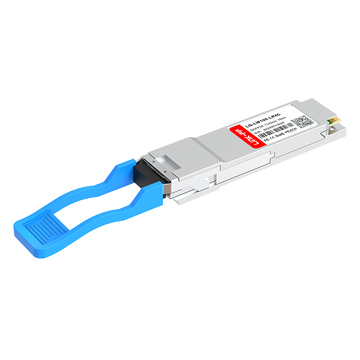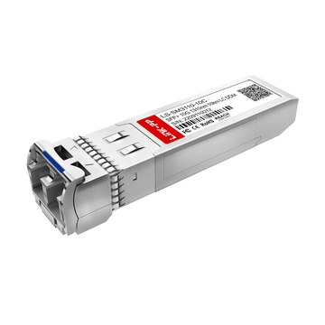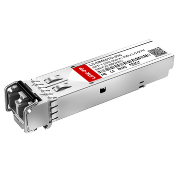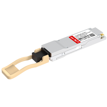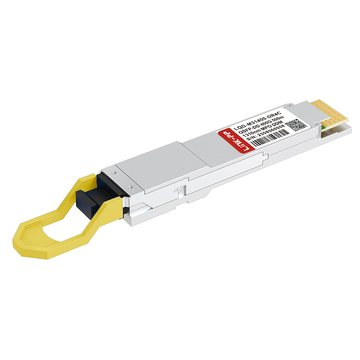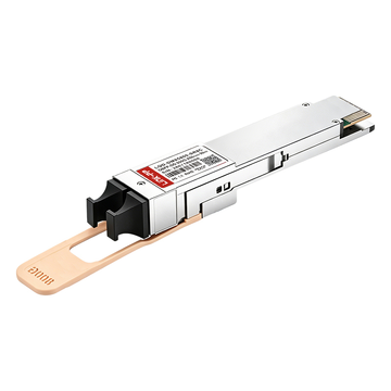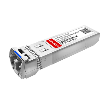
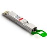
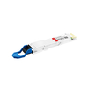
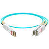







Ethernet technology has evolved significantly over the past few decades, increasing from 100Mbps Fast Ethernet to 800Gbps high-speed connectivity. This evolution has introduced a growing number of Ethernet physical-layer standards, each designed for different transmission speeds, media types, and network distances. As data centers, enterprise networks, and AI infrastructure demand higher bandwidth, understanding these standards becomes increasingly important.
When exploring optical transceivers, network engineers frequently encounter designations such as 100BASE-FX, 1000BASE-BX10, 10GBASE-LR, 25GBASE-ER, 100GBASE-FR1, and 400GBASE-LR4. These names are not random product codes. They follow IEEE Ethernet naming conventions that describe how data is transmitted over copper or fiber-optic media.
This guide explains IEEE Ethernet BASE terminology from 100M to 800G, connecting the naming conventions with practical transceiver specifications and network applications. Specifically, it covers:
-
The meaning and structure of Ethernet BASE designations.
-
Common speed prefixes and optical transmission suffixes.
-
Representative Ethernet PHY standards from 100Mbps to 800Gbps.
-
Fiber types, wavelengths, optical lanes, and transmission distances.
-
How to select compatible optical transceivers for different Ethernet applications.
Understanding these fundamentals makes it easier to interpret optical module datasheets, compare Ethernet interfaces, and plan network upgrades. It also provides a clearer picture of how LINK-PP's optical transceiver portfolio supports connectivity requirements across multiple Ethernet generations.
What Does BASE Mean in IEEE Ethernet Standards?
BASE in IEEE Ethernet terminology refers to baseband transmission. It describes a communication method in which Ethernet signals are transmitted over a physical medium using baseband signaling rather than broadband frequency-division transmission.
The term appears in Ethernet designations such as 100BASE-TX, 1000BASE-SX, 10GBASE-LR, and 100GBASE-DR. Although these interfaces operate at different speeds and use different transmission media, they share the BASE designation.
The Meaning of BASE in Ethernet Naming
BASE is short for baseband, a method of transmitting digital signals over a communication medium without dividing the medium into multiple independent broadband frequency channels.
In Ethernet standards, BASE identifies the transmission approach used by the physical layer. It does not specify whether the connection uses copper or optical fiber.
For example:
-
100BASE-TX: 100Mbps Ethernet over twisted-pair copper.
-
100BASE-FX: 100Mbps Ethernet over optical fiber.
-
1000BASE-SX: 1Gbps Ethernet over short-wavelength multimode fiber.
-
10GBASE-LR: 10Gbps Ethernet over long-reach single-mode fiber.
-
100GBASE-DR: 100Gbps Ethernet over a short-reach single-mode optical interface.
These examples demonstrate that BASE is common to both copper and fiber Ethernet technologies.
It is also important to distinguish BASE from the suffix following it. BASE identifies the transmission method, while the remaining designation provides information about the particular Ethernet PHY implementation.
How IEEE 802.3 Defines Ethernet Physical Layers
IEEE 802.3 is the primary family of standards defining Ethernet operation. It specifies how Ethernet devices communicate through different physical interfaces and transmission media.
An Ethernet connection involves several functional layers:
-
MAC (Media Access Control): Handles Ethernet frame transmission and reception, including addressing and access to the transmission medium.
-
PHY (Physical Layer): Defines the physical signaling and communication interface.
-
PCS (Physical Coding Sublayer): Performs encoding, decoding, and other physical-layer functions.
-
PMA (Physical Medium Attachment): Handles functions such as serialization, deserialization, and lane distribution.
-
PMD (Physical Medium Dependent): Defines the characteristics of the physical transmission interface, including optical or electrical signaling requirements.
Different IEEE 802.3 PHY specifications support different media and operating distances.
For example:
-
Copper PHYs operate over twisted-pair cabling or other electrical media.
-
Multimode fiber PHYs support short-distance optical transmission.
-
Single-mode fiber PHYs support longer-distance Ethernet connections.
-
Backplane PHYs provide electrical connectivity within networking equipment.
For optical transceivers, the PMD specification is particularly important because it defines optical transmission characteristics such as wavelengths, optical power, and supported fiber interfaces.
IEEE 802.3 standards provide the technical foundation for interoperability between Ethernet equipment from different manufacturers, provided the relevant PHY specifications and implementation requirements are satisfied.
The Basic Structure of an Ethernet BASE Designation
Most Ethernet BASE designations follow a recognizable structure:
[Data Rate]BASE-[Physical Layer Variant]
The three main elements are:
-
Data rate: Indicates the nominal Ethernet transmission speed.
-
BASE: Identifies baseband transmission.
-
PHY suffix: Describes the physical-layer implementation, including media type, reach category, or optical configuration.
Consider 1000BASE-SX as an example:
-
1000 indicates 1Gbps Ethernet.
-
BASE indicates baseband transmission.
-
SX identifies a short-wavelength optical Ethernet implementation.
Similarly, 10GBASE-LR can be interpreted as 10Gbps baseband Ethernet using a long-reach optical PHY.
High-speed Ethernet designations can contain additional numbers and letters. For example, 400GBASE-LR4 identifies a 400Gbps single-mode optical PHY with four optical wavelengths and a specified reach of up to 10km.
Not every suffix follows exactly the same naming logic. Therefore, the complete IEEE PHY designation should always be checked when evaluating an optical transceiver.
Decoding the Three Main Parts of Ethernet BASE Terminology
Understanding Ethernet BASE terminology requires more than recognizing the speed prefix. The suffix also provides important information about the physical interface, fiber type, and transmission distance.
These naming conventions become particularly useful when comparing optical transceivers with similar data rates but different optical architectures.
Ethernet Speed Prefixes: 100M to 800G
The numerical prefix identifies the nominal Ethernet data rate. Ethernet has progressed through multiple generations, with each generation supporting higher network bandwidth.
The following table summarizes common Ethernet speed designations and their corresponding data rates.
| Ethernet Designation | Nominal Data Rate | Common Applications |
|---|---|---|
| 100BASE | 100Mbps | Industrial networks, legacy access networks |
| 1000BASE | 1Gbps | Enterprise LANs, access switches |
| 10GBASE | 10Gbps | Enterprise uplinks, data center connections |
| 25GBASE | 25Gbps | Server-to-switch connectivity |
| 40GBASE | 40Gbps | Data center aggregation |
| 100GBASE | 100Gbps | Data center uplinks and spine networks |
| 200GBASE | 200Gbps | High-performance data center networks |
| 400GBASE | 400Gbps | Hyperscale data centers and AI infrastructure |
| 800GBASE | 800Gbps | Next-generation AI and cloud networks |
A key concept in high-speed Ethernet is the relationship between aggregate bandwidth and individual lane rates.
For example:
-
40G Ethernet can use four 10Gbps optical lanes.
-
100G Ethernet can use four 25Gbps lanes or a single 100Gbps optical lane.
-
400G Ethernet can use four 100Gbps lanes or eight 50Gbps lanes.
-
800G Ethernet can use eight 100Gbps optical lanes.
The exact lane architecture depends on the PHY specification.
Higher-speed Ethernet also increasingly uses PAM4 (4-level Pulse Amplitude Modulation), which carries two bits per signaling symbol and helps increase the amount of information transmitted per lane.
Understanding the difference between aggregate bandwidth and lane speed is essential when interpreting 200G, 400G, and 800G optical module specifications.
Understanding Common Suffixes: T, SX, LX, BX, SR, LR, ER, and ZR
The suffix in an Ethernet BASE designation identifies the physical-layer implementation. Some suffixes indicate the transmission medium, while others describe optical reach or wavelength characteristics.
The following terms appear frequently in Ethernet standards and optical transceiver datasheets.
Common Ethernet suffixes:
-
T: Twisted-pair copper Ethernet. For example, 100BASE-TX and 1000BASE-T.
-
SX: Short-wavelength optical Ethernet, commonly using 850nm multimode fiber. For example, 1000BASE-SX.
-
LX: Long-wavelength optical Ethernet, commonly associated with 1310nm transmission. For example, 1000BASE-LX.
-
BX: Bidirectional optical transmission over a single fiber strand, using different wavelengths for transmit and receive. For example, 1000BASE-BX10.
-
SR: Short Reach, generally associated with multimode fiber in common data center applications.
-
LR: Long Reach, generally associated with single-mode fiber.
-
ER: Extended Reach, commonly used for longer-distance single-mode optical connections.
-
ZR: An industry designation commonly associated with very-long-reach optical modules. Its exact specifications depend on the implementation, and it is not a universal IEEE PHY suffix.
These suffixes provide a convenient way to identify the general characteristics of Ethernet interfaces. However, they should not be treated as universal definitions of wavelength or transmission distance.
For instance, SR typically indicates multimode fiber, but the actual reach depends on the Ethernet generation and fiber grade. Similarly, LR does not represent exactly the same distance across every Ethernet standard.
Understanding High-Speed Optical Suffixes: DR, FR, LR, and Multi-Lane Variants
High-speed Ethernet introduces additional suffixes to distinguish optical transmission architectures.
The most common designations include DR, FR, LR, and ER.
-
DR (Data Center Reach): Typically represents short-reach single-mode fiber transmission, commonly around 500m in 100G, 400G, and 800G applications.
-
FR (Short-to-Medium Reach): Generally represents single-mode optical transmission over approximately 2km.
-
LR (Long Reach): Commonly represents single-mode optical transmission over approximately 10km, although specific standards define different reaches.
-
ER (Extended Reach): Typically supports longer single-mode fiber connections, often around 40km.
Numbers following these suffixes provide additional information about the optical architecture.
For example:
-
SR4: Four optical lanes for short-reach transmission.
-
DR4: Four optical lanes for single-mode data center reach.
-
FR4: Four optical wavelengths using wavelength-division multiplexing.
-
LR4: Four optical wavelengths for long-reach transmission.
-
ER4: Four optical wavelengths for extended-reach transmission.
-
LR8: Eight optical wavelengths for long-reach transmission.
It is important to distinguish between parallel optical lanes and wavelength-division multiplexing (WDM).
Parallel optics transmit data through multiple physical fiber paths. WDM combines multiple optical wavelengths over the same fiber pair, allowing several optical channels to share a single fiber infrastructure.
The number in a suffix does not always mean the same thing in every implementation. For accurate interpretation, always refer to the complete PHY specification.
100M to 10G Ethernet BASE Standards: The Foundation of Optical Connectivity
Ethernet standards from 100Mbps to 10Gbps form the foundation of many enterprise networks, industrial communication systems, and fiber access infrastructures.
Although newer Ethernet generations support much higher bandwidth, 100M, 1G, and 10G interfaces remain widely used because of their established infrastructure and broad equipment compatibility.
100BASE-T and 100BASE-FX: Fast Ethernet Connectivity
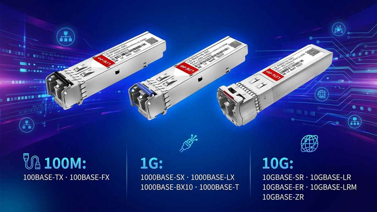
100Mbps Ethernet, commonly called Fast Ethernet, supports both copper and optical transmission.
The 100BASE family includes several physical-layer implementations.
100BASE-T
100BASE-T describes 100Mbps Ethernet over twisted-pair copper cabling. Common implementations include:
-
100BASE-TX: The widely deployed Fast Ethernet copper interface.
-
100BASE-T2: An IEEE-defined implementation using two pairs of balanced copper wiring.
-
Other 100BASE-T PHY variants defined for specific copper environments.
100BASE-FX
100BASE-FX is an optical Fast Ethernet PHY that uses multimode fiber, typically operating around 1300nm.
Its common characteristics include:
-
Transmission medium: Multimode fiber.
-
Wavelength: Approximately 1300nm.
-
Typical connector: SC or LC, depending on the equipment and transceiver implementation.
-
Typical reach: Up to 2km under the specified fiber and operating conditions.
100BASE-FX is commonly found in industrial Ethernet equipment, legacy enterprise networks, and fiber-based access connections.
The main difference between 100BASE-T and 100BASE-FX is the transmission medium. Copper Ethernet uses electrical signaling, while 100BASE-FX transmits optical signals through fiber.
For fiber-based Fast Ethernet networks, 100M optical transceivers provide a practical way to connect switches, media converters, and industrial networking devices.
1000BASE-SX, 1000BASE-LX, 1000BASE-BX10, and 1000BASE-T
Gigabit Ethernet increased network capacity to 1Gbps and introduced several widely adopted physical-layer options.
The main differences between these standards involve fiber type, wavelength, transmission distance, and cabling requirements.
| Ethernet Standard | Medium | Typical Wavelength | Typical Maximum Reach |
|---|---|---|---|
| 1000BASE-SX | Multimode fiber | 850nm | 220–550m, depending on fiber |
| 1000BASE-LX | Primarily single-mode fiber | 1310nm | Up to 10km |
| 1000BASE-BX10 | Single-mode, single-fiber bidirectional | 1310nm/1490nm | 10km |
| 1000BASE-T | Twisted-pair copper | N/A | 100m |
1000BASE-SX is designed for short-distance Gigabit Ethernet over multimode fiber. It commonly uses 850nm VCSEL-based optical transmission.
1000BASE-LX uses 1310nm optical transmission and is primarily associated with single-mode fiber. It is commonly used for campus networks and building-to-building connections.
1000BASE-BX10 uses bidirectional optical transmission over a single strand of single-mode fiber. Instead of using separate fibers for transmit and receive, it uses different wavelengths in opposite directions.
A typical BX arrangement includes:
-
BX-U: Transmits at 1310nm and receives at 1490nm.
-
BX-D: Transmits at 1490nm and receives at 1310nm.
The two modules must be used as a matched pair.
1000BASE-T operates over four pairs of twisted-pair copper cabling and is commonly used for desktop connections, servers, and access switches.
In optical Gigabit Ethernet networks, SFP transceivers remain one of the most widely deployed module formats. LINK-PP provides 1G optical transceiver options covering different fiber types, wavelengths, and transmission distances, helping support both existing infrastructure and network expansion.
10GBASE-SR, 10GBASE-LR, 10GBASE-ER, 10GBASE-LRM, and 10GBASE-ZR
10Gbps Ethernet introduced a wider range of optical transmission options, supporting both short-distance multimode fiber and long-distance single-mode fiber applications.
The main 10G optical designations include SR, LR, ER, and LRM, while ZR is commonly used in industry product naming.
| Designation | Fiber Type | Wavelength | Typical Reach |
|---|---|---|---|
| 10GBASE-SR | Multimode | 850nm | 300m on OM3; 400m on OM4 |
| 10GBASE-LR | Single-mode | 1310nm | 10km |
| 10GBASE-ER | Single-mode | 1550nm | 40km |
| 10GBASE-LRM | Legacy multimode and specified fiber types | 1310nm | Up to 220m |
| 10GBASE-ZR | Single-mode | Commonly 1550nm | Commonly 80km, depending on implementation |
10GBASE-SR
SR is designed for short-reach multimode fiber connections. It is widely used in data centers for switch-to-server and switch-to-switch connectivity.
10GBASE-LR
LR uses 1310nm single-mode optical transmission and supports links up to 10km. It is a common solution for enterprise backbone connections and data center interconnections.
10GBASE-ER
ER extends the transmission distance to approximately 40km using 1550nm single-mode optics. It is suitable for metropolitan and long-distance enterprise network applications.
10GBASE-LRM
LRM stands for Long Reach Multimode. It was developed to support 10Gbps Ethernet over legacy multimode fiber infrastructure, including older FDDI-grade fiber under specified operating conditions.
10GBASE-ZR
ZR is a common industry designation for extended-reach 10G optical modules, often supporting approximately 80km over single-mode fiber. Unlike 10GBASE-LR and 10GBASE-ER, ZR should not be presented as a standard IEEE 10GBASE PHY designation.
SFP+ is the dominant compact form factor for many 10G optical applications. Available options include SR, LR, ER, and extended-reach implementations, depending on equipment compatibility and network requirements.
Selecting the correct 10G optical module requires checking the actual fiber infrastructure, link distance, and optical specifications rather than relying on the 10G speed designation alone.
25G to 100G Ethernet BASE Standards: The Transition to High-Speed Optical Networking
The transition from 25G to 100G Ethernet represents an important development in data center networking. Higher lane rates, improved optical architectures, and more efficient fiber utilization enable networks to support increasing traffic demands.
These standards are especially relevant to server connectivity, leaf-spine architectures, enterprise aggregation, and cloud data centers.
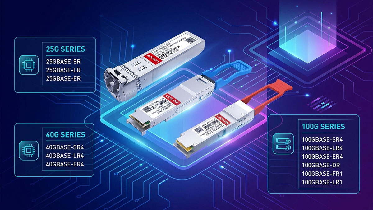
25GBASE-SR, 25GBASE-LR, and 25GBASE-ER
25Gbps Ethernet provides a higher-bandwidth alternative to 10Gbps connections while maintaining a compact optical module architecture.
The three important optical reach categories are SR, LR, and ER.
| Designation | Fiber Type | Wavelength | Typical Reach |
|---|---|---|---|
| 25GBASE-SR | Multimode | 850nm | 70m on OM3; 100m on OM4 |
| 25GBASE-LR | Single-mode | 1310nm | 10km |
| 25GBASE-ER | Single-mode | 1310nm | 40km |
25GBASE-SR is designed for short-distance multimode fiber transmission, making it suitable for data center server connections.
25GBASE-LR uses single-mode fiber and supports transmission distances of up to 10km. It is commonly used in campus networks and longer-distance switch connections.
25GBASE-ER provides extended-reach transmission over single-mode fiber, typically supporting up to 40km.
SFP28 is the common optical module form factor associated with 25G Ethernet. Compared with SFP+, it supports higher data rates while retaining a similar compact physical interface.
Typical 25G applications include:
-
Server-to-switch connections in data centers.
-
Leaf switch uplinks.
-
Enterprise network aggregation.
-
Cloud infrastructure and high-density switching.
40GBASE-SR4, 40GBASE-LR4, and 40GBASE-ER4
40Gbps Ethernet introduced multiple optical transmission architectures, particularly parallel multimode transmission and wavelength-division multiplexing over single-mode fiber.
The three representative PHYs are 40GBASE-SR4, 40GBASE-LR4, and 40GBASE-ER4.
| Designation | Fiber Type | Optical Architecture | Typical Reach |
|---|---|---|---|
| 40GBASE-SR4 | Multimode | 4 optical lanes | 100m on OM3; 150m on OM4 |
| 40GBASE-LR4 | Single-mode | 4 CWDM wavelengths | 10km |
| 40GBASE-ER4 | Single-mode | 4 LAN-WDM wavelengths | 40km |
40GBASE-SR4
SR4 uses four optical transmit lanes and four optical receive lanes over multimode fiber. Each lane carries 10Gbps, resulting in an aggregate data rate of 40Gbps.
It commonly uses MPO/MTP connectors and is designed for short-distance data center connections.
40GBASE-LR4
LR4 uses four optical wavelengths transmitted over a pair of single-mode fibers. The wavelengths are typically:
-
1271nm
-
1291nm
-
1311nm
-
1331nm
These four CWDM wavelengths are multiplexed onto one transmitting fiber and demultiplexed at the receiving end.
40GBASE-ER4
ER4 also uses four optical wavelengths over single-mode fiber, but its wavelength arrangement is different from LR4. It uses LAN-WDM wavelengths around 1295.56nm, 1300.05nm, 1304.58nm, and 1309.14nm.
This architecture supports longer transmission distances, typically up to 40km.
QSFP+ is the common form factor for 40G optical transceivers. It supports different optical implementations, allowing network designers to select between multimode parallel optics and single-mode WDM solutions.
100GBASE-SR4, 100GBASE-LR4, 100GBASE-ER4, 100GBASE-FR1, 100GBASE-LR1, and 100GBASE-DR
100Gbps Ethernet supports several optical architectures, including parallel multimode transmission, multi-wavelength single-mode transmission, and single-wavelength optical interfaces.
Although all these standards provide an aggregate data rate of 100Gbps, their optical configurations and transmission distances differ significantly.
| Designation | Fiber Type | Optical Architecture | Typical Reach |
|---|---|---|---|
| 100GBASE-SR4 | Multimode | 4 optical lanes | 70m on OM3; 100m on OM4 |
| 100GBASE-LR4 | Single-mode | 4 LAN-WDM wavelengths | 10km |
| 100GBASE-ER4 | Single-mode | 4 LAN-WDM wavelengths | 40km |
| 100GBASE-FR1 | Single-mode | 1 wavelength (1310nm) | 2km |
| 100GBASE-LR1 | Single-mode | 1 wavelength (1310nm) | 10km |
| 100GBASE-DR | Single-mode | 1 optical lane (1310nm) | 500m |
100GBASE-SR4
SR4 uses four optical lanes for transmission and four for reception over multimode fiber. Each lane operates at approximately 25Gbps.
It is commonly implemented in QSFP28 optical modules for short-distance data center connections.
100GBASE-LR4
LR4 uses four optical wavelengths over single-mode fiber, supporting up to 10km. Its LAN-WDM wavelength arrangement enables four 25Gbps optical channels to share a fiber pair.
100GBASE-ER4
ER4 extends the single-mode optical reach to approximately 40km using four LAN-WDM wavelengths.
It is suitable for longer-distance network connections where standard LR4 reach is insufficient.
100GBASE-FR1
FR1 represents a different optical architecture. Instead of using four wavelengths, it transmits the full 100Gbps Ethernet signal over one optical wavelength on single-mode fiber.
Its standardized reach is at least 2km.
100GBASE-LR1
LR1 also uses one optical wavelength but extends the specified transmission distance to at least 10km over single-mode fiber.
Both FR1 and LR1 use PAM4 optical signaling, allowing 100Gbps transmission over a single optical lane.
100GBASE-DR
DR uses a single optical lane over single-mode fiber and supports a reach of up to 500m. It is widely associated with parallel single-mode optical implementations in QSFP28 and other 100G module designs, depending on the host interface.
The difference between DR, FR1, and LR1 is primarily their optical reach and link architecture. These options allow network designers to match the optical interface to the actual distance and fiber infrastructure.
QSFP28 remains one of the most widely used 100G optical transceiver form factors. LINK-PP's 100G optical module portfolio covers different transmission distances and optical architectures, providing connectivity options for data center, enterprise, and service provider networks.
200G to 400G Ethernet BASE Standards: Higher Bandwidth and Advanced Optical Architectures
200G and 400G Ethernet represent a major step toward higher-density networking. These standards use faster optical lanes, PAM4 signaling, and more advanced optical architectures to increase aggregate bandwidth.
They are particularly important in hyperscale data centers, cloud infrastructure, high-performance computing, and AI networking environments.
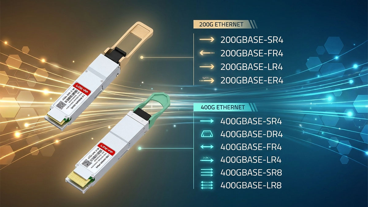
Understanding 200GBASE Optical Interfaces
200Gbps Ethernet doubles the bandwidth of 100G Ethernet and supports multiple optical configurations for different fiber types and transmission distances.
Representative 200G optical PHYs include SR4, FR4, LR4, and ER4.
| Designation | Fiber Type | Optical Architecture | Typical Reach |
|---|---|---|---|
| 200GBASE-SR4 | Multimode | 4 optical lanes | 100m on OM4 |
| 200GBASE-FR4 | Single-mode | 4 CWDM wavelengths | 2km |
| 200GBASE-LR4 | Single-mode | 4 LAN-WDM wavelengths | 10km |
200GBASE-SR4
SR4 uses four optical lanes over multimode fiber. Each lane carries approximately 50Gbps, providing an aggregate bandwidth of 200Gbps.
It is designed for short-distance data center connections.
200GBASE-FR4
FR4 uses four optical wavelengths over a pair of single-mode fibers, supporting approximately 2km transmission.
The four CWDM wavelengths allow multiple optical channels to share the same fiber pair.
200GBASE-LR4
LR4 uses four optical wavelengths over single-mode fiber and supports approximately 10km transmission.
It is suitable for longer-distance data center connections and enterprise network aggregation.
400GBASE-SR4, 400GBASE-SR8, 400GBASE-DR4, 400GBASE-FR4, 400GBASE-LR4, and 400GBASE-LR8
400Gbps Ethernet supports several optical PHY architectures designed for different transmission distances and fiber environments.
Some use multiple parallel optical lanes, while others combine several wavelengths over a single fiber pair.
| Designation | Fiber Type | Optical Architecture | Typical Reach |
|---|---|---|---|
| 400GBASE-SR4 | Multimode | 4 optical lanes | 100m |
| 400GBASE-SR8 | Multimode | 8 optical lanes | 100m on OM4 |
| 400GBASE-DR4 | Single-mode | 4 optical lanes | 500m |
| 400GBASE-FR4 | Single-mode | 4 CWDM wavelengths | 2km |
| 400GBASE-LR4 | Single-mode | 4 LAN-WDM wavelengths | 10km |
| 400GBASE-LR8 | Single-mode | 8 LAN-WDM wavelengths | 10km |
400GBASE-SR4
SR4 uses four optical lanes over multimode fiber, with each lane supporting approximately 100Gbps. It is designed for short-reach optical connectivity in data centers.
400GBASE-SR8
SR8 uses eight optical lanes to deliver 400Gbps aggregate bandwidth. It supports short-distance multimode fiber connections, commonly reaching 100m over OM4.
400GBASE-DR4
DR4 uses four 100Gbps optical lanes over single-mode fiber. It supports transmission distances up to 500m and is commonly used in data center interconnects.
400GBASE-FR4
FR4 uses four optical wavelengths over single-mode fiber, with each wavelength carrying approximately 100Gbps. The four wavelengths are multiplexed onto a single fiber pair, supporting a reach of up to 2km.
Its CWDM4 architecture helps reduce fiber usage compared with parallel optical interfaces.
400GBASE-LR4
LR4 is a standardized 400G optical PHY that uses four wavelengths over single-mode fiber. It supports transmission distances up to 10km.
400GBASE-LR8
LR8 uses eight optical wavelengths over single-mode fiber and supports transmission distances up to 10km.
Compared with LR4-6, LR8 uses a different wavelength architecture and supports a longer standardized reach.
At 400G, the module form factor becomes an important consideration. QSFP-DD and OSFP are two major form factors used in 400G optical networking.
They support high-density switch ports and are designed to accommodate the electrical and thermal requirements of higher-speed transceivers.
How 400G Optical Modules Support Data Center Expansion
400G Ethernet is becoming increasingly important as cloud computing, distributed applications, and AI workloads generate more network traffic.
Its higher aggregate bandwidth allows data centers to increase network capacity without proportionally increasing the number of physical switch ports.
Common 400G applications include:
-
Spine-to-spine and spine-to-leaf connections.
-
High-bandwidth data center interconnects.
-
AI cluster networking.
-
Cloud infrastructure and hyperscale switching.
-
Enterprise backbone upgrades.
Several factors influence the deployment of 400G optical modules:
Port density
Higher-speed optical modules allow more bandwidth to be delivered through each switch port, improving network capacity and rack utilization.
Power consumption
As optical transmission speeds increase, power consumption becomes an important factor in overall data center efficiency.
Thermal management
400G modules generate more heat than many lower-speed transceivers. Proper airflow, module spacing, and cooling design are essential.
Fiber infrastructure
The choice between SR4, SR8, DR4, FR4, and LR8 depends on the available fiber type, connector configuration, and required link distance.
At LINK-PP, our 400G optical transceiver range addresses different data center connectivity requirements, including multimode and single-mode applications. The available QSFP-DD and OSFP solutions also provide options for network equipment using different high-speed module interfaces.
For organizations upgrading from 100G or 200G, selecting the appropriate 400G optical architecture helps maintain compatibility with existing fiber infrastructure while preparing for higher network capacity.
800G Ethernet BASE Standards: The Next Step in High-Bandwidth Connectivity
800G Ethernet represents another major increase in network bandwidth, particularly for AI training clusters, hyperscale data centers, and high-performance computing infrastructure.
IEEE 802.3df-2024 introduced standardized physical-layer specifications for 800Gbps Ethernet alongside additional 400Gbps PHYs. These specifications define different optical transmission approaches for short- and medium-distance applications.
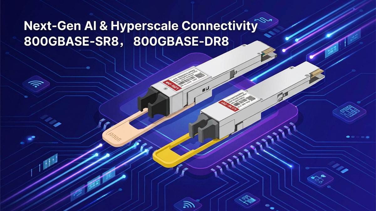
What Is 800GBASE Ethernet?
800GBASE refers to Ethernet physical-layer implementations supporting an aggregate data rate of 800Gbps.
Compared with 400G Ethernet, 800G increases aggregate bandwidth while using high-speed electrical and optical lanes.
Representative 800G optical PHY designations include:
| Designation | Fiber Type | Optical Architecture | Typical Reach |
|---|---|---|---|
| 800GBASE-SR8 | Multimode | 8 optical lanes | 100m |
| 800GBASE-DR8 | Single-mode | 8 optical lanes | 500m |
800GBASE-SR8
SR8 supports short-reach multimode fiber transmission over distances of up to 100m under specified conditions.
It uses eight optical lanes to deliver the aggregate 800Gbps bandwidth.
800GBASE-DR8
DR8 uses eight optical transmit lanes and eight receive lanes over single-mode fiber. Each lane carries approximately 100Gbps, providing an aggregate bandwidth of 800Gbps.
It supports transmission distances up to 500m.
800G Optical Transceiver Architectures and Form Factors
800G optical transceivers must accommodate much higher data rates, making electrical interface design, optical lane integration, power consumption, and thermal management increasingly important.
Two major form factors used in 800G optical networking are QSFP-DD800 and OSFP.
QSFP-DD800
QSFP-DD800 is an enhanced version of the QSFP-DD architecture designed to support 800Gbps connectivity.
Its main characteristics include:
-
High-density module design.
-
Support for eight high-speed electrical lanes.
-
Compatibility with suitable 800G host interfaces.
-
Applications in high-density switching and data center infrastructure.
OSFP
OSFP is another major form factor developed for high-speed optical connectivity.
Its design provides additional space for electrical and thermal requirements associated with 400G and 800G modules.
OSFP is commonly used in high-performance switches and hyperscale data center platforms.
Several technical factors distinguish 800G transceivers from earlier generations:
-
PAM4 signaling: Supports higher data rates per lane.
-
Optical engine integration: Helps manage multiple high-speed optical channels.
-
Power efficiency: Becomes increasingly important as module bandwidth increases.
-
Thermal design: Requires careful consideration of module temperature and switch airflow.
-
Signal integrity: High-speed electrical interfaces require precise PCB and host connector design.
The choice between QSFP-DD800 and OSFP depends on the switch platform, host port design, cooling capabilities, and supported transceiver specifications.
800G Ethernet Applications and LINK-PP Product Coverage
800G Ethernet is particularly relevant to infrastructure where large volumes of data must move between servers, switches, and computing systems with minimal network bottlenecks.
Important applications include:
-
AI training and inference clusters.
-
Hyperscale cloud data centers.
-
High-performance computing environments.
-
High-capacity data center interconnects.
-
Next-generation spine and leaf switching architectures.
As network bandwidth increases, optical transceivers must provide not only higher data rates but also reliable signal transmission, suitable thermal performance, and compatibility with the host platform.
LINK-PP's optical transceiver portfolio covers Ethernet connectivity requirements from 100M to 800G, supporting different network generations and deployment scenarios.
This broad coverage is useful for organizations operating mixed-speed networks. Rather than treating every infrastructure upgrade as a completely separate project, network teams can evaluate optical connectivity across multiple Ethernet generations within one product portfolio.
When planning an 800G deployment, it is important to verify:
-
The switch's supported 800G module form factor.
-
The required optical PHY, such as SR8 or DR8.
-
Fiber type and connector configuration.
-
Required transmission distance.
-
Power consumption and thermal requirements.
-
Interoperability between the transceiver and host equipment.
These considerations help ensure that 800G optical modules meet the actual requirements of the network environment.
How to Choose the Right Optical Transceiver Based on IEEE BASE Standards
Choosing an optical transceiver involves more than matching its nominal data rate to a switch port. The correct module must also support the required Ethernet PHY, fiber type, wavelength, transmission distance, connector, and equipment compatibility.
A systematic selection process helps reduce interoperability issues and ensures reliable network operation.
Match the Optical Module to the Ethernet PHY Standard
The first step is to identify the Ethernet PHY supported by the networking equipment.
Two optical modules may both support 100Gbps Ethernet but use completely different optical interfaces.
For example:
-
100GBASE-SR4 uses multimode fiber and parallel optical lanes.
-
100GBASE-LR4 uses four wavelengths over single-mode fiber.
-
100GBASE-DR uses a single-wavelength single-mode optical interface.
-
100GBASE-FR1 uses one optical wavelength for a 2km single-mode connection.
Although their nominal data rates are identical, these modules are not interchangeable without considering the physical interface.
Before selecting a transceiver, verify the following:
-
Ethernet data rate: Confirm whether the port supports 1G, 10G, 25G, 40G, 100G, 200G, 400G, or 800G.
-
PHY specification: Match the module with the supported SR, LR, DR, FR, ER, or other relevant PHY.
-
Lane configuration: Check the number of electrical and optical lanes.
-
Host interface: Confirm the switch or router supports the required module form factor.
-
Vendor compatibility: Verify the transceiver's coding, firmware requirements, and compatibility with the target equipment.
The complete PHY specification is more important than the speed designation alone.
Identify Fiber Type, Wavelength, and Transmission Distance
Fiber type and optical wavelength determine whether a transceiver can operate correctly over the installed fiber infrastructure.
The two main fiber categories used in Ethernet optical networking are multimode fiber and single-mode fiber.
Multimode Fiber (MMF)
Multimode fiber supports multiple light propagation modes and is commonly used for short-distance connections.
Common types include:
-
OM1: Legacy multimode fiber.
-
OM2: 50/125μm multimode fiber.
-
OM3: Laser-optimized multimode fiber.
-
OM4: Higher-bandwidth laser-optimized multimode fiber.
-
OM5: Wideband multimode fiber designed to support multiple wavelengths.
Most modern short-reach Ethernet optical modules use OM3 or OM4 fiber.
Single-Mode Fiber (SMF)
Single-mode fiber supports a single propagation mode and is widely used for longer-distance Ethernet transmission.
OS2 is commonly deployed in enterprise networks, telecom infrastructure, and data centers requiring single-mode optical connectivity.
Common Optical Wavelengths
Different optical transceiver types use different wavelengths depending on the transmission technology.
| Wavelength | Common Applications | Fiber Type |
|---|---|---|
| 850nm | 1G SX, 10G SR, 25G SR, 40G SR4, 100G SR4 | Multimode |
| 1310nm | 1G LX, 10G LR, 25G LR/ER, 100G DR/FR1/LR1 | Primarily single-mode |
| 1490nm | 1G BX bidirectional transmission | Single-mode |
| 1550nm | 10G ER and extended-reach optical applications | Single-mode |
| CWDM wavelengths | 40G LR4, 200G FR4, 400G FR4 | Single-mode |
| LAN-WDM wavelengths | 40G ER4, 100G LR4/ER4 | Single-mode |
The wavelength alone does not determine the maximum transmission distance. Optical power budget, receiver sensitivity, fiber attenuation, dispersion, and connector loss also affect link performance.
When selecting an optical transceiver, confirm that both ends of the connection use compatible optical specifications.
Consider Form Factor, Compatibility, and Network Upgrade Requirements
The transceiver form factor determines the module's physical interface and host connectivity. Different Ethernet speeds use different module families, although some form factors support multiple data rates.
Common optical transceiver form factors include:
| Form Factor | Common Ethernet Applications |
|---|---|
| SFP | 100M, 1G |
| SFP+ | 10G |
| SFP28 | 25G |
| QSFP+ | 40G |
| QSFP28 | 100G |
| QSFP56 | 200G |
| QSFP-DD | 200G, 400G and platform-dependent higher-speed applications |
| QSFP-DD800 | 800G |
| OSFP | 400G and 800G |
The exact data rates supported depend on the host platform and module implementation. A form factor alone does not guarantee compatibility with every PHY or Ethernet speed.
When planning network upgrades, consider these factors:
1. Host equipment compatibility
Check the switch, router, or server specifications to confirm supported optical module types and vendor coding requirements.
2. Breakout connectivity
Some high-speed ports support breakout configurations. For example, a 400G port may support multiple lower-speed connections when the switch and transceiver architecture allow it.
3. Fiber infrastructure
Evaluate whether existing fiber cabling can support the required transmission distance and optical interface. This can help reduce unnecessary infrastructure changes.
4. Power and thermal requirements
High-speed transceivers generate heat and consume power. Make sure the networking equipment can support the selected module's power and cooling requirements.
5. Network migration strategy
A network upgrade may involve multiple Ethernet generations operating simultaneously. Selecting transceivers across 1G, 10G, 25G, 100G, 400G, and 800G helps support a gradual transition.
At LINK-PP, we provide optical transceiver solutions covering Ethernet applications from 100M to 800G. Our portfolio includes different module speeds, form factors, optical architectures, and transmission distances for enterprise networks, data centers, and high-performance computing environments.
We also support multi-vendor compatibility requirements, helping network teams identify suitable alternatives for different switch and router platforms.
For a more efficient selection process, use the LINK-PP Compatibility Tool to check optical transceiver alternatives for your original equipment model. You can also contact our technical team with the equipment model, required data rate, and transmission distance to obtain a suitable recommendation and quotation.
Conclusion
IEEE Ethernet BASE terminology provides a standardized way to identify Ethernet data rates and physical-layer transmission technologies. From 100BASE-T and 1000BASE-BX10 to 100GBASE-FR1, 400GBASE-LR4, and 800GBASE-DR8, each designation communicates important information about the Ethernet PHY and its transmission characteristics.
Understanding these naming conventions makes it easier to compare optical transceivers, identify compatible fiber interfaces, and plan network upgrades across different Ethernet generations.
The most important points to remember are:
-
BASE refers to baseband transmission, not exclusively optical connectivity.
-
The numerical prefix identifies the nominal Ethernet data rate, from 100Mbps to 800Gbps.
-
The suffix describes the physical-layer implementation, including media, reach, and optical architecture.
-
Fiber type and wavelength determine which optical transmission environment a module supports.
-
SR, DR, FR, LR, and ER represent different optical reach categories, with exact specifications depending on the PHY standard.
-
Module form factors such as SFP, SFP28, QSFP28, QSFP-DD, and OSFP define physical interfaces rather than Ethernet standards themselves.
As Ethernet continues to evolve, selecting the correct optical transceiver requires a clear understanding of both IEEE PHY specifications and equipment compatibility.
At LINK-PP, we support optical connectivity requirements across the full 100M–800G Ethernet range, helping customers identify suitable transceiver solutions for different network architectures and equipment platforms.
Visit the LINK-PP Official Store to explore our optical transceiver portfolio. If you are looking for an alternative to an original equipment manufacturer (OEM) optical module, use our Compatibility Tool to identify corresponding compatible models or contact our technical team for a quotation. Besides, we offer a 15-day no-reason return and exchange policy for standard-stock items. For quality-related issues, LINK-PP covers the return shipping costs.